Road Safety and Simulation
International Conference
RSS2013
October 23-25, 2013
Rome, Italy
Augmented and Mixed Reality as a tool
for evaluation of Vehicle Active Safety Systems
Björn Blissing
Research assistant
Swedish National Road and Transport Research Institute VTI, SE-581 95 Linköping, Sweden
bjorn.blissing@vti.se, +46 13 20 40 77
Fredrik Bruzelius
Researcher
Swedish National Road and Transport Research Institute VTI, SE-581 95 Linköping, Sweden
fredrik.bruzelius@vti.se, +46 31 750 26 05
Johan Ölvander
Professor
Linköping University, Department of Management and Engineering SE-581 83 Linköping, Sweden
2
ABSTRACT
Even though the realism of driving simulators increases constantly, there is a potential issue with how representative the test is compared to a real life scenario. An alternative to simulators is to present a mixture of real and simulated environment to the driver and perform the scenario at a test track when driving a real vehicle. This enables an efficient way of testing that inherits many of the advantages of driving simulators as well as some of the advantages of physical testing in prototype vehicles. The present paper is a compilation of previous research in augmented reality in vehicle driving situations, focusing on technical limitations of Head-Mounted-Displays.
Keywords: Augmented reality, Active safety systems, Performance evaluation,
Human-in-the-loop
METHOD
The main method used in this research is to compile knowledge from previously published conference papers, journal articles and other related material regarding use of augmented and mixed reality in the automotive industry.
The following research questions were of special interest: (1) In which context has augmented and mixed reality been used within the automotive sector? (2) What are the recent developments and key problems in these areas? (3) What are important future research topics within these areas?
INTRODUCTION
Modern vehicles are often equipped with a variety of active safety systems. For example systems designed to keep the vehicle in the current lane, avoid collisions or mitigate the effects of an imminent collision (Jansson 2005), either by autonomous steering or braking.
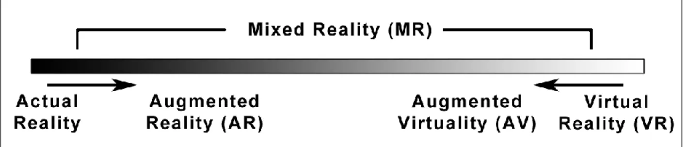
These systems require exhaustive testing with many hours in test vehicles on test tracks as well as in real traffic. Cost and efficiency is a major motivator to perform more testing virtually in simulated environments. The human machine interaction can be tested virtually in driving simulators. A step towards real testing, yet remaining in a partly simulated environment, is to use augmented reality, as illustrated in Figure 1.
Mixed reality has been used in many contexts associated with vehicles such as a learning tool for driving school instructors (Regenbrecht et al. 2005). By equipping both student and instructor with a head mounted display (HMD), the student can be subjected to driving scenarios which trigger active safety systems. Typical scenarios would be scenarios too complex or too dangerous to experience in actual reality.
Augmented reality could also be used to evaluate and improve performance in computer vision systems when it comes to detecting, classifying and tracking objects in active safety functions. This could be used to replace the time consuming task of recording countless videos for all variations of a scenario (Nilsson et al. 2010). Another application were augmented reality could be used is to visualize navigation systems, showing GPS navigation information on the windshield with a head up display (Kim & Dey 2009). Applications can also be found in vehicle to vehicle (V2V) communication. Equipping the vehicles with windshield-installed cameras and distributing the video feed to vehicles in proximity could be used to make vehicles seemingly transparent, which could be useful for increasing visibility in for example overtaking scenarios (Gomes et al. 2012).
Augmented reality is also used to evaluate active safety systems during the product development phase (Bock et al. 2005). By combining the visual input of the driver with a computer generated objects, it is possible to perform tests that are impossible to perform in actual reality due to e.g. risk exposure to the driver, etc. The mixture of simulated and real environment in this setting shares many positive properties of a completely simulated environment; such as repeatability, and of actual reality; such as realism in driving, motion- and haptic feedback.
In (Bock et al. 2005), a head mounted display with optical see-through is used to add the computer simulated object to the drivers field of view. The focus plane is set at 10 m to let the driver have focus on both the road ahead and the simulated vehicles. Validation tests comparing augmented reality against actual reality showed significant similarity in all tested maneuvers, except cut-in scenarios due to late perception of the vehicle cutting in (Bock et al. 2007). (Moussa et al. 2012) tested a system using a fixed front facing video camera and a head mounted display with video see-through with similar results.
Recent studies (Karl et al. 2013) have shown that participants were able to drive a real car in a pure virtual environment with similar longitudinal behavior as real driving, although drivers showed increased reaction time and slower accelerations. One benefit of using a pure virtual world is the elimination of the registration errors, but it also reintroduced simulator sickness. The project have a similar agenda as the one found in (Bock et al. 2005; Moussa et al. 2012; Karl et al. 2013), i.e. use augmented reality to test active safety functions and their impact to the driver. The objective of the present study is to evaluate different techniques for presenting augmented reality to the driver with a focus on the requirements for graphical presentation. Hence, some inherited requirements on for example perceived realism and timing needs to be considered when choosing and designing the engineering solution. Other aspects may also need to be considered such as cost, weight and practical implementation issues.
4
DISPLAY SYSTEMS
The main objective of the display system is to display the surrounding environment to the driver with as little distortion as possible compared to the real environment and with the possibility to add an artificial object, for example a simulated vehicle, to the drivers’ field of view.
Two major types of display systems can be used in this context; windshield mounted/projected or head mounted displays. Both types can be of either video see-through or of optical see-through variety. Optical through implies that a semi-transparent display is used while video see-through implies that cameras are bypassed to a non-transparent display.
Windshield mounted displays are by nature more involving to install in the test vehicle. The displays require a high resolution compared to head mounted displays as the drivers’ eye is situated at a larger distance from the actual screen. Yet, this solution does not imply an advantage over head mounted displays when it comes to perceptual issues such as depth perception. Windshield mounted projections (head up displays) suffers from the same drawbacks and have in addition problems with intensity/contrast issues. Hence, head mounted display solutions have a clear advantage in this application.
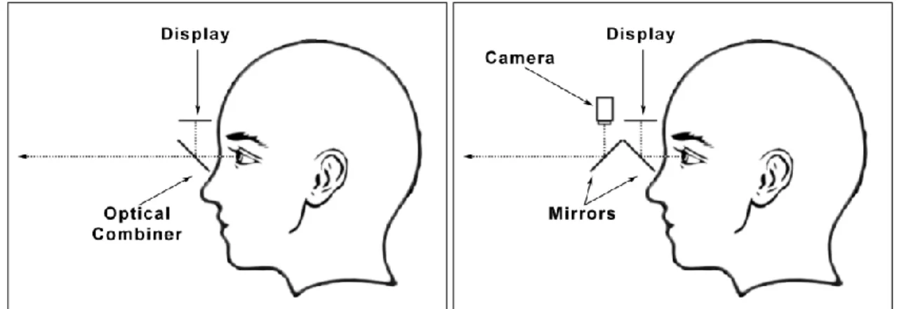
The first head mounted display was suggested by (Sutherland 1968). In an optical see-though HMD the environment is displayed directly to the user and the computer graphics are superimposed via an optical combiner, usually a semitransparent mirror (Figure 2a). This gives the user a direct view of the environment without any delay or distortion. However, this solution often suffers from registration errors, where the generated image and the real world object are out of alignment. This can be caused by factors such as system lag, accuracy of tracking sensors, calibration error, optical distortion, and misalignment of the environment model (Azuma & Bishop 1994; Holloway 1997). An optical see-through HMD is usually not capable of showing graphics that occlude the environment (see Figure 3a), because the optical combiner adds the light from the display to the light from the environment.
Figure 2: Schematic sketch of HMD with optical see-through (a) and video see-through (b) Video see-through HMDs provide a view of the environment by capturing the environment with a camera. The image of the environment is then combined with the computer graphics and displayed to the user (Figure 2b). A video see-through HMD is capable of displaying graphics that completely occlude the image from the cameras (see Figure 3b), since the display can
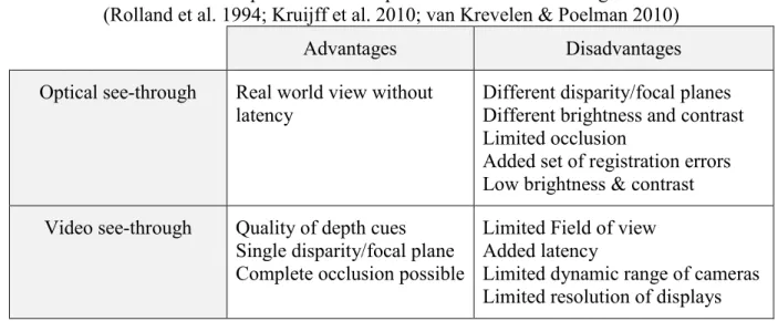
completely replace parts of the captured image with the computer generated graphics. Short comings of video see-through HMD are for example matching the field of view of the cameras with the field of view of the user (Rolland & Fuchs 2000), and also in the limited dynamic range of the cameras, which could pose a problem when driving in varied lighting conditions. The trade-off issues between optical and video see-through HMD solutions is given in Table 1
Table 1: Tradeoff options between optical- and video see-through devices. (Rolland et al. 1994; Kruijff et al. 2010; van Krevelen & Poelman 2010)
Advantages Disadvantages
Optical see-through Real world view without latency
Different disparity/focal planes Different brightness and contrast Limited occlusion
Added set of registration errors Low brightness & contrast Video see-through Quality of depth cues
Single disparity/focal plane Complete occlusion possible
Limited Field of view Added latency
Limited dynamic range of cameras Limited resolution of displays One of the major short comings of video see-through is however the latency of visual sensory input. Studies have shown that low latency is important for cognitive functions such as; sense of presence, spatial cognition and awareness (Meehan et al. 2003; Papadakis et al. 2011).
Theoretical analysis of manual control systems have suggest a maximum visual transport delay of 50 ms for ground vehicles (Allen & Dimarco 1984). The same study also showed that increased visual latency has more effect on control system stability than increased latency in vehicle model computation or motion cueing. In the study by (Karl et al. 2013) the visual latency was much higher, viz. 150 ms. The study showed longer reaction times and smoother acceleration for the test subjects, which the authors suggests could depend on increased simulator sickness.
Figure 3: Typical optical see-through occlusion errors (a) vs. Video see-through occlusion (b). Simulated truck superimposed on real image of road.
6
TRACKING SYSTEM
The present application of augmented reality is so called oriented augmented reality, which means that the simulated graphical object is oriented in time and space in respect to the viewer. This implies that a tracking of the motion between the drivers head and the ground that the vehicle is traveling on requires to be estimated, i.e. a tracking problem. This problem can be divided into a tracking problem between the drivers head and the vehicle and another tracking problem between the vehicle and the ground.
Tracking of the driver can be done via numerous techniques which each have advantages and disadvantages, see Table 2. Hybrid solutions which combine multiple techniques to remedy the individual drawbacks can also be used.
Table 2: Tradeoffs between common tracking techniques (Bhatnagar 1993; Rolland et al. 2001; Foxlin 2002).
Advantages Disadvantages
Mechanical Good precision and accuracy
High update rate Low lag
Limited range Possible gimbal lock
Can obstruct both movement and view (occlusion)
Ultrasonic Multiple receivers/users
Small & lightweight sensors No occlusion problem
Low update rate
Sensitive to acoustic noise, occlusion of sensor,
temperature- and humidity changes
Inertial Good precision and accuracy
High update rate
Small & lightweight sensors No occlusion problem
Accumulative error over time
Electromagnetic Good precision and accuracy High update rate
Low lag
Small & lightweight sensors No occlusion problem
Sensitive to electromagnetic noise and metallic objects Accuracy decreases with distance
Image-based Multiple receivers/users Good precision and accuracy No occlusion problem
Significant lag
Tracking of the vehicle is normally performed with satellite navigation systems combined with inertial systems to increase accuracy.
CONCLUSIONS AND FUTURE WORK
The present project will develop a similar test environment as in (Bock et al. 2005; Moussa et al. 2012; Karl et al. 2013) with a display system to add virtual objects to the drivers view. The focus in Bock et al. was on the graphical presentation to the driver while the tracking problem of driver and vehicle motion relative to the road and environment discussed only briefly. Furthermore, the present study aims at developing a video see-through system, but instead of a fixed camera as in Moussa et al. cameras mounted on the HMD will be used.
From the discussion in previous sections, it can be concluded that a head mounted display have advantages over windshield mounted systems when it comes to installation. Head mounted displays might influence the driver as the driver needs to wear a helmet like installation with a significant weight. The practical aspects are the predominant reasons for the head mounted display solution in this application.
The optical see-through solution will have advantages over video see-through solution when considering representing the real surrounding environment as the video see-through will by nature add latency. However, as perceived realism is highly rated in the present application, the video see-through solution is considered a better choice as it can add objects with arbitrary level of occlusion and potentially without registration error. Although there is a need to further investigate the problem with added latency that is incurred from the video see-through system. Future steps in the development of the environment will be to study the latency effect, according to methods suggested in (Bloche et al. 1997), on the drivers capabilities and how to reduce the latency in both tracking system as well as in graphical system for video see-through HMDs. The tracking problem itself will be investigated firstly by the separation suggested earlier and secondly using the video cameras attached to the head mounted video see-through helmet.
ACKNOWLEDGEMENTS
This project is mainly founded by the VINNOVA/FFI project ‘Next Generation Test Methods for Active Safety Functions’ dnr. 2011-01819. Additional funding has also been provided by the Swedish National Road and Transport Research Institute.
REFERENCES
Allen, W.R. & Dimarco, R.J., 1984. Effects of transport delays of manual control system performance. In S. G. Hart & E. J. Hartzell, eds. Proceedings of the 20th annual conference on manual control. Moffet Field, CA, US: NASA, pp. 185–201.
Azuma, R. & Bishop, G., 1994. Improving static and dynamic registration in an optical see-through HMD. In
Proceedings of the 21st annual conference on Computer graphics and interactive techniques - SIGGRAPH ’94. New York, New York, USA: ACM Press, pp. 197–204.
Bhatnagar, D.K., 1993. Position trackers for Head Mounted Display systems : A survey, Chapel Hill, NC, USA. Bloche, S., Kemeny, A. & Reymond, G., 1997. Transport delay analysis in driving simulators with head mounted
8
Bock, T., Maurer, M. & Farber, G., 2007. Validation of the Vehicle in the Loop (VIL) - A milestone for the simulation of driver assistance systems. In 2007 IEEE Intelligent Vehicles Symposium. Istanbul, Turkey: IEEE, pp. 219–224.
Bock, T., Siedersberger, K.-H. & Maurer, M., 2005. Vehicle in the Loop - Augmented Reality Application for Collision Mitigation Systems. In Fourth IEEE and ACM International Symposium on Mixed and Augmented
Reality (ISMAR’05). Vienna, Austria: IEEE Computer Society.
Foxlin, E., 2002. Motion tracking requirements and technologies. In K. M. Stanney & K. S. Hale, eds. Handbook of
virtual environment technology. Mahwah, NJ, USA: CRC Press, pp. 163–210.
Gomes, P., Olaverri-Monreal, C. & Ferreira, M., 2012. Making Vehicles Transparent Through V2V Video Streaming. IEEE Transactions on Intelligent Transportation Systems, 13(2), pp.930–938.
Holloway, R., 1997. Registration error analysis for augmented reality. Presence: Teleoperators and Virtual
Environments, 6(4), pp.413–432.
Jansson, J., 2005. Collision avoidance theory with application to automotive collision mitigation. Ph.D. Thesis, Linköping University, Linköping, Sweden. Linköping Studies in Science and Technology. Dissertations No. 950.
Karl, I. et al., 2013. Driving Behavior and Simulator Sickness While Driving the Vehicle in the Loop: Validation of Longitudinal Driving Behavior. IEEE Intelligent Transportation Systems Magazine, 5(1), pp.42–57.
Kim, S. & Dey, A.K., 2009. Simulated augmented reality windshield display as a cognitive mapping aid for elder driver navigation. Proceedings of the 27th international conference on Human factors in computing systems -
CHI 09, p.133.
Van Krevelen, D.W.F. & Poelman, R., 2010. A survey of augmented reality technologies, applications and limitations. The International Journal of Virtual Reality, 9(2), pp.1–20.
Kruijff, E., Swan, J. & Feiner, S., 2010. Perceptual issues in augmented reality revisited. In International
Symposium on Mixed and Augmented Reality - ISMAR.
Meehan, M. et al., 2003. Effect of latency on presence in stressful virtual environments. In IEEE Virtual Reality,
2003. Proceedings. IEEE Computer Society, pp. 141–148.
Milgram, P. et al., 1994. Augmented reality: A class of displays on the reality-virtuality continuum. Telemanipulator
and Telepresence Technolgies, 2351, pp.282–292.
Moussa, G., Radwan, E. & Hussain, K., 2012. Augmented Reality Vehicle system: Left-turn maneuver study.
Transportation Research Part C: Emerging Technologies, 21(1), pp.1–16.
Nilsson, J. et al., 2010. Performance evaluation method for mobile computer vision systems using augmented reality. In 2010 IEEE Virtual Reality Conference (VR). IEEE, pp. 19–22.
Papadakis, G. et al., 2011. The effect of tracking delay on awareness states in immersive virtual environments. In
Proceedings of the 10th International Conference on Virtual Reality Continuum and Its Applications in Industry - VRCAI ’11. New York, New York, USA: ACM Press, p. 475.
Regenbrecht, H., Baratoff, G. & Wilke, W., 2005. Augmented reality projects in the automotive and aerospace industries. IEEE Computer Graphics and Applications, (December), pp.48–56.
Rolland, J.P., Davis, L.D. & Baillot, Y., 2001. A survey of tracking technology for virtual environments. In W. Barfield & T. Caudell, eds. Fundamentals of Wearable Computers and Augmented Reality. Hillsdale, NJ, USA: CRC Press, pp. 67–112.
Rolland, J.P. & Fuchs, H., 2000. Optical Versus Video See-Through Head-Mounted Displays in Medical Visualization. Presence: Teleoperators and Virtual Environments, pp.287–309.
Rolland, J.P., Holloway, R. & Fuchs, H., 1994. A comparison of optical and video see-through head-mounted displays. SPIE Telemanipulator and Telepresence Technologies, 2351, pp.293–307.
Sutherland, I.E., 1968. A head-mounted three dimensional display. In AFIPS ’68 Proceedings of the December