Model Based Testing for
Non-Functional Requirements
Master Thesis in Software Engineering
School of Innovation, Design and Engineering
Mälardalen University
Västerås, Sweden
June, 2010
Vijaya Krishna Cherukuri Piyush Gupta
krisveejay.83@gmail.com piyushguptaiet@gmail.comSupervisors:
Pär Pålhed, Ericsson AB and Antonio Cicchetti, Mälardalen University
Examiner:
Page | 2
Contents
ABBREVIATIONS ... 9
TERMINOLOGY ... 11
1. INTRODUCTION ... 12
1.1 ORGANIZATION OF THE THESIS ... 12
2. BACKGROUND ... 13
2.1 TESTING (BLACK-BOX AND WHITE BOX) ... 13
2.2 WHAT IS MODEL BASED TESTING? ... 13
2.2.1 Designing the test model ... 14
2.2.2 Selection of test generation criteria ... 14
2.2.3 Test Generation ... 14
2.2.4 Test Execution ... 14
2.3 MODES OF MODEL BASED TESTING ... 14
2.4 SCOPE OF MODEL BASED TESTING ... 15
2.5 BENEFITS OF MODEL BASED TESTING ... 15
2.6 MBT IN ERICSSON ... 16
3. THESIS ... 18
3.1 PROBLEM DEFINITION ... 18
3.2 GOALS ... 18
3.3 LIMITATIONS ... 18
4. MBT FOR NON-FUNCTIONAL REQUIREMENTS TESTING ... 20
4.1 PROBLEMS IN MODELING NON-FUNCTIONAL REQUIREMENTS ... 20
4.2 NEW PROPOSED METHOD FOR NON-FUNCTIONAL REQUIREMENTS VERIFICATION USING MBT ... 21
4.3 PROS AND CONS OF THE NEW PROCESS ... 21
5. TOOLS OVERVIEW ... 24
5.1 QTRONIC ... 24
5.1.1 Workflow ... 24
5.1.1.1 Modeling SUT ... 24
5.1.1.2 Test Configuration and Generation ... 26
5.2 MOTES ... 27
5.2.1 Workflow ... 27
5.2.1.1 Modeling IUT ... 27
5.2.1.2 Prepare Test Data ... 28
5.2.1.3 Importing Models and Test data ... 28
5.2.1.4 Defining Test Coverage/Goal ... 28
5.2.1.5 Selecting Test Generation Engine ... 29
5.2.1.6 Generating the test cases ... 29
5.3 MATELO ... 29
5.4 MODELJUNIT ... 31
Page | 3 5.4.1.1 Modeling SUT ... 31 5.4.1.2 Test Configuration ... 33 5.4.1.3 Test Generation ... 34 5.5 MBTTIGRIS ... 34 5.5.1 Work flow... 34 5.5.1.1 Modeling SUT ... 35 5.5.1.2 Test Configuration ... 35 5.5.1.3 Test Generation ... 37 6. TOOLS COMPARISON... 38
6.1 FUNCTIONALITY AND USABILITY ... 38
6.1.1 Graphical User Interface ... 38
6.1.2 Libraries ... 45
6.1.3 Design Rules ... 45
6.1.3.1 Modeling Strategy ... 45
6.1.3.2 Test Data Specification ... 46
6.1.3.3 Test Configuration Definition ... 46
6.1.3.4 Modeling Language ... 46 6.1.4 Document Generation ... 47 6.1.5 Requirement Tracking ... 47 6.2 FLEXIBILITY ... 47 6.2.1 Operating System... 47 6.2.2 Tools Integration ... 48 6.2.3 Script Languages ... 48 6.2.4 Adaptability ... 49 6.3 PRICING ... 49
6.3.1 Licensing and Support ... 49
6.3.2 Education ... 50
6.4 SUPPORT FOR NON FUNCTIONAL TESTING ... 50
6.5 APPLICABILITY IN CURRENT SUTENVIRONMENT ... 50
7. CASE STUDIES ... 51
7.1 SYSTEM UNDER TEST :IPSECURITY PROTOCOL ... 51
7.2 TOOLS SELECTION ... 53
7.3 CASE STUDY WITH MODELJUNIT ... 53
7.3.1 Objectives of case study ... 53
7.3.1.1 Modeling the SUT... 54
7.3.1.2 Test Generation ... 57
7.4 CASE STUDY WITH QTRONIC ... 57
7.4.1 Objectives of case study ... 58
7.4.1.1 Modeling the SUT... 58
8. DISCUSSION ... 63
8.1 QTRONIC ... 63
8.2 MODELJUNIT ... 66
9. CONCLUSION ... 69
Page | 4
Page | 5
Index of Tables
Table 1 : Sample QML code ... 25
Table 2 : Sample ModelJUnit model code ... 32
Table 3: List of Generators for MBT Tigris ... 36
Table 4: List of Stop Criteria for MBT Tigris ... 36
Table 5 : Test Configuration code for ModelJUnit ... 56
Table 6: QML code for handling maximum number of objects creation ... 61
Table 7 : Data Values for the Initial Functional Models in Qtronic ... 63
Table 8 : Data values for Requirement 1 using Approaches 2 and 5 in Qtronic ... 64
Table 9 : Data values for Requirement 2 using approach 5 in Qtronic ... 65
Table 10 : Data values of Requirement 3 with different look-ahead depths ... 65
Table 11 : Data Values of the initial functional model in ModelJUnit ... 67
Table 12 : Data Values of Requirement 1 modeling in ModelJUnit ... 67
Page | 6
Index of Figures
Figure 1: MBT Process ... 15
Figure 2: MBT process in Ericsson ... 17
Figure 3: MBT process in Ericsson for Modeling Functional Requirements ... 17
Figure 4: New Process flow for Verification of Non-Functional Requirement ... 22
Figure 5: Workflow of Qtronic ... 24
Figure 6 : Modeler Provided with Qtronic ... 26
Figure 7: Workflow in Motes [12] ... 27
Figure 8: MaTeLo Modeler Window ... 30
Figure 9: MaTeLo Testor Window ... 30
Figure 10: ModelJUnit Generated Graphical EFSM Model ... 33
Figure 11: Workflow of MBT Tigris ... 35
Figure 12: Qtronic GUI Main Window... 39
Figure 13 : Motes Project Structure ... 39
Figure 14: Motes Directive Definition Window ... 40
Figure 15 : Motes Main GUI Window ... 40
Figure 16 : Motes GUI showing Error Message ... 41
Figure 17: ModelJUnit GUI Main Window ... 42
Figure 18: ModelJUnit GUI Test Configuration Window ... 42
Figure 19: MBT Tigris Main Window ... 43
Figure 20: MaTeLo Modeler Windows ... 44
Figure 21: MaTeLo Testor Window ... 44
Figure 22: IPSEC Implementation in the System ... 52
Figure 23: Graphical model covering functional requirements of SUT ... 55
Figure 24: Graphical model covering both functional and Non-Functional requirements of SUT ... 56
Figure 25: Existing Qtronic Functional Model ... 59
Figure 26 : Qtronic approach for NFR by introducing new state ... 60
Page | 7
Abstract
Model Based Testing (MBT) is a new-age test automation technique traditionally used for Functional Black-Box Testing. Its capability of generating test cases by using model developed from the analysis of the abstract behavior of the System under Test is gaining popularity. Many commercial and open source MBT tools are available currently in market. But each one has its own specific way of modeling and test case generation mechanism that is suitable for varied types of systems. Ericsson, a telecommunication equipment provider company, is currently adapting Model Based Testing in some of its divisions for functional testing. Those divisions haven’t yet attempted adapting Model Based Testing for non-functional testing in a full-pledged manner. A comparative study between various MBT tools will help one of the Ericsson’s testing divisions to select the best tool for adapting to its existing test environment. This also helps in improving the quality of testing while reducing cost, time and effort. This thesis work helps Ericsson testing division to select such an effective MBT tool. Based on aspects such as functionality, flexibility, adaptability, performance etc., a comparative study is carried out on various available MBT tools and a few were selected among them: Qtronic, ModelJUnit and Elvior Motes. This thesis also helps to understand the usability of the selected tools for modeling of non-functional requirements using a new method. A brief idea of modeling the non-functional requirements is suggested in this thesis. A System under Test was identified and its functional behavior was modeled along with the non functional requirements in Qtronic and ModelJUnit. An experimental analysis, backed by observations of using the new proposed method indicates that the method is efficient enough to carry out modeling non-functional requirements along with modeling of functional requirements by identifying the appropriate approach.
Page | 8
Acknowledgements
We take this opportunity to thank and acknowledge the co-operation and support – both moral and technical extended by people who helped us in our endeavor to complete the thesis. We shall always cherish our association with them.
We would like to thank Mr. Pär Pålhed, our Project Supervisor at Ericsson who has been a constant source of advice, encouragement and above all for the continuous support he has provided throughout the thesis work.
A Special thanks to Mr. Antonio Cicchetti, our Project Supervisor at Mälardalen University, for taking his time to listen to our ideas, guiding us well in writing the thesis report and providing us his valuable feedback.
We would also like to thank Mr. Hakan Fredriksson, Mr. Ebrahim Amirkhani and all other test team members of the project. Their assistance and camaraderie helped us to tide over the difficulties encountered.
A special mention to Mr. Michael Lidén and Mr. Athanasios Karapantelakis from Conformiq for their training and support in learning the tool.
Last but not the least; we would like to thank our student group from Tata Consultancy Services at Mälardalen University, who stood by us in both good and bad times, and made it a wonderful journey throughout our Master’s program.
Page | 9
Abbreviations
AH Authentication Header
API Application Programming Interface CSV Comma Separated Value
CPP Cello Packet Platform CPU Central Processing Unit DC Design Configuration
EFSM Extended Finite State Machine ESP Encapsulated Security Payload FSM Finite State Machine
GNU GNU's Not UNIX
GUI Graphical User Interface HTML Hypertext Markup Language IKE Internet Key Exchange IPSec IP Security
IUT Implementation under Test JAR Java Archive File
MBT Model Based Testing MC Marcov Chain
MDE Model driven Engineering
MDPE Model Driven Performance Engineering MTL Motes Transition Language
OOPS Object Oriented Programming Specification QML Qtronic Modeling Language
QTP Quick Test Professional SA Security Association
Page | 10 SAD Security Association Database
SPD Security Policy Database SUT System under Test
SysML System Modeling Language
TTCN-3 Test and Test Control Notation version 3 TC Test Case
TCL Tool Command Language UI User Interface
UML Unified Modeling Language XMI XML Metadata Interchange XML Extensible Markup Language
Page | 11
Terminology
Functionality
Functionality can be defined as the supported operations, capabilities and utilities provided by the software.
Usability
Usability is the quality property of software that defines how easy the software can be used. Some usability attributes of the software can be its learnability, efficiency, error Handling and debugging capability.
Flexibility
Flexibility is also the quality attribute of software that defines its ability to change or adapt easily in response to different configurations and system requirements.
FSM
Finite state machine is used to model behavior of the SUT by means of graph. It has finite number of states. Each of its nodes represents a state and arcs which represents the transitions from current state to next one, which is performed by means of certain actions.
EFSM
Extended Finite State Machine is an enhanced version of FSM also used to model behavior of SUT. In EFSM, each transition might be associated with the Boolean expression known as Guard Condition. If this guard is evaluated to true then only transition is fired, some actions are performed and SUT changes its state from current to next.
Marcov Chains
A Markov chain is also used to model behavior of SUT where next state depends only on the current state. There is a transition that causes the changes state, and the transition probabilities associated with various state-changes. These sets of all states and transition probabilities collectively called as Markov chain.
Test Harness
A test harness is a collection of tools and test data configured to automate the test execution process. It consists of Test execution engine and the Test script repository. It performs the task of calling functions with supplied parameters and prints out and performs analysis on the results. The test harness is glue to the SUT, which is tested using an automation framework.
Page | 12
1. Introduction
For decades, billions of dollars are lost due to software errors. Sometimes they affect lives also. They are results of poor software quality. Software testing has become one of the important and crucial factors in Software Development Life Cycle. As per researcher's estimate, on an average approximately 50-60% of total development time is dedicated for Software testing in Industries [16]. As the needs of developing new kinds of software related products increase, the demand for releasing them in to market with efficient quality and additional advanced features at cheaper cost increases in order to withstand the competition. This results in designing of more and more complex systems in lesser amount of time. More complex the system is, even more is the effort required to test it. A single and simple change in the system may increase the time and effort of testing the system proportionally. Also with the increasing demand in software products, customers expect more reliable, efficient and a quality software product that contains advanced features and functionality. The competition between many companies forces the manufacturer to deliver the product with above prerequisites within a short period of time. This leads to a short period of testing time. There comes the need of test automation. Automation of testing not only reduces the effort and time but also the cost incurred as testing needs to be done regressively when meeting tight project schedules.
The traditional manual preparation of test cases is done by analyzing the functionality and working of the system. But in automation techniques, the testing process involves usage of tools and scripts to generate test cases and perform testing in a quick and efficient manner. One good automation technique is Model Based Testing. It is nothing but the application of model based designing to software testing process. This process involves development of a model that describes the test cases, test data and the system under test execution environment and using that model test cases are generated. The main advantage of using MBT is that the time require for modeling the behavior is less than manual test case writing and execution. Also it generates wide range of test cases which more often may not be derived manually. MBT is basically used for functional black-box testing. Functional requirements of a system that describe the behavior of the System under Test can be easily modeled as the functional aspects of the system involve specific sequence of actions. Whereas the non-functional requirements require analysis models defining both the structure and behavior of the analyzed system, resource requirements, branch probabilities, and details about factors due to contention of resources [17]. For the same reason it is difficult to have a generic way of modeling non-functional requirements of a system. Though MBT is used to some extent for robustness testing, there is no full-pledged established way of checking it for other non-functional attributes such as performance, security etc. It is still an area under development.
1.1 Organization of the thesis
This Master’s Thesis has the following outline. Chapter 2 provides background information for several key areas related to this Master’s Thesis. Chapter 3 presents the problem formulation. Related information on use of MBT for testing non-functional requirements is provided in Chapter 4. Chapter 5 gives an overview of some MBT tools. Section 6 provides a comparative study on the tools discussed in Chapter 5. In Chapter 7, case study on a telecom system for testing Non-Functional requirements using MBT tools is presented. The discussions on the results are presented in Chapter 8.
Page | 13
2. Background
This chapter provides the background information regarding our thesis work. Section 2.1 discusses about black-box and white box testing and introduces Model-based testing. The consecutive sections discusses about the modes, benefits and existing limitations of Model Based Testing. Section 2.6 gives an overview of current MBT process in Ericson.
2.1 Testing (Black-box and White Box)
Software testing and fault detection activities are mostly inexactly and inadequately understood, especially in the complex systems. But they are very much crucial for the success of the project and if in case it is a product, it is necessary to ensure better quality [18]. Though manual testing may yield many defects in a software application, it is a laborious and time consuming task. Automating the tasks may reduce the time to more extent. Once the tests are automated, they can be run quickly and instant results are generated.
In the scope of test automation there exits two prominent methodologies, Black-Box and White-Box techniques [19]. Black box testing refers to the testing of the response of the system in terms of its behaviour. Black box testing involves exploration of various possible inputs and the corresponding possible outputs from them. It does not bother about the internal implementation of the system or the process adapted for the functionality. White-Box testing on the other side looks under the cover of the system, taking into consideration the way the system is implemented, internal data structures and possible logic involved in the coding etc.
The difference lies in the areas on which both the testing methodologies focus. Black-box testing focuses on the outcome irrespective of the inside processes involved to achieve those outcomes. A White-box testing concern with the details and the testing perspective is complete only if the sum of all the parts contributes to the system as whole [20].
One of the variants of black box testing is the Model Based testing. As the time preceded Model based Testing is used for adapting to White Box methodology also. The next sections briefly discuss about what Model-based Testing is and how it can be used for efficient generation of test cases.
2.2 What is Model Based Testing?
More often complexity is resolved by considering abstraction. Same is the case in software testing. Considering the software testing at an abstract level not only helps in reducing the complexity but also be useful to generate efficient test cases in short period of time. Model based testing is one technique that lets the tester to consider the System under Test in an abstract manner. The behaviour of the whole SUT is modelled to generate test cases. According to Wikipedia , MBT is defined as "software testing in which test cases are derived in whole or in part from a model that describes some (usually functional) aspects of the system under test (SUT) ” [1].
Model based testing is a process used to generate abstract test cases by using the abstract formal models of the SUT. Later these abstract test cases are converted into executable test cases and the test cases thus generated are automated. The following are the four important stages of MBT application in industry.
Page | 14
2.2.1 Designing the test model
The abstract behaviour of the entire system is modelled by using standard modelling languages such as UML, SysML etc. Most commonly used methods are Finite State Machines. But they are large and abstract for modelling real systems. So Extended Finite State Machines are generally used. For storing data EFSMs have the facility of adding state variables and also they facilitate the guard conditions and actions that are required to update state variables during transactions. The transactions are mapped with the requirements to ensure traceability and later used to generate test cases.
2.2.2 Selection of test generation criteria
A huge number of test cases may be generated usually based on the designed model. But prioritization of the test cases is needed in order to structure the testing process and reduce test effort. Standard test generation criterion such as boundary value analysis [2], equivalence class partitioning, cycle coverage etc are generally used. But the underlying factor is the selection of any criteria that covers all the requirements.
2.2.3 Test Generation
This is an automatic process done by using some of the available MBT tools in market. Using the designed model, high level abstract test sequences are generated by the tool that uses some branch traversal algorithms. These abstract test sequences are independent of the language that is used to write the test cases and of the SUT environment [2]. Each test sequence contains the input parameters, required actions and expected outputs. Since they are at abstract level, they cannot be directly executed in the SUT. Modifications are required to be done in the abstract test sequences in order to automate. Abstract test cases are translated into executable test cases by mapping the data values in the data model to real values in the SUT [21]. This can be done by using an intermediate platform called SUT adapter which is used to covert and automate the abstract test cases. The generated test cases from the test model are structured and organized into multiple test suites and can be saved in repositories such as HP Test Director and IBM Rational Quality Manager repository etc.
2.2.4 Test Execution
The generated and modified test cases are executed in a standard and automated test environment or even run manually on SUT, and the results are compared with that of expected results. If there are failed test cases, they are verified whether it is a fault or bug in SUT or due to construction of behavior during modeling.
2.3 Modes of Model Based Testing
The timing related to test case generation and test case execution gives rise to another dimension of MBT which is referred to as the modes of MBT. There are two modes of MBT, Offline and Online. Online testing is the process in which both the test generation and test execution processes are combined and used at a time, where the instant result is used for pruning the MBT process. In Offline testing mode, test execution is followed by test generation phase. The test generation phase generates an artifact called test suite, which is later interpreted by the test execution phase of MBT [22].The test cases are generated before they are run on the SUT in offline mode.
Page | 15
Figure 1: MBT Process
The online mode is useful for identifying the non-deterministic paths of SUT whereas in offline mode it is difficult as the test cases does not involve creating sequences, but are created as graphs and trees. But the advantage of having offline mode is that it helps for efficient management of test cases which further is useful for executing same test cases in different kind of environments at different times [23].
2.4 Scope of Model Based Testing
Currently MBT is used mostly in system and acceptance testing phases of software development life cycle. It may not be efficiently used for unit and component testing of systems. It is a time consuming effort and moreover a repetitive task as the functional aspects of the individual entities can be covered when the whole system or sub-system is modeled in the later phases.
2.5 Benefits of Model Based Testing
The main benefit of MBT is to generate wide range of test cases in short span of time. Even though modeling takes considerable amount of time, it will always be less than deriving the test cases manually. Moreover if there is a change in any of the requirements, it is a heavier and painful task to reflect the similar changes in test cases or scripts written manually. But in MBT, it is easier to modify the model than to modify the test suite. Apart from that, MBT form of testing is less ad-hoc and adapts systematic coverage of test cases providing a complete control on test coverage. It is easy to detect flaws in modeling at earlier stages based on the analysis of test cases that are derived. MBT also facilitates easy traceability by considering the matching of test cases with the requirements.
MBT helps to establish a systematic way of testing. It sticks to main goal of testing, i.e., finding faults in SUT. But the number of faults detected depends upon the way in which the system behavior is modeled. A wrong understanding of requirements may lead to incorrect modeling of the behavior and thus leads to wrong faults which can be at times confusing. It is like adding new faults rather than finding some
Page | 16 existing ones. Factors such as test selection criteria chosen from the experience and expertise of the Tester's knowledge with SUT drives modeling and test generation.
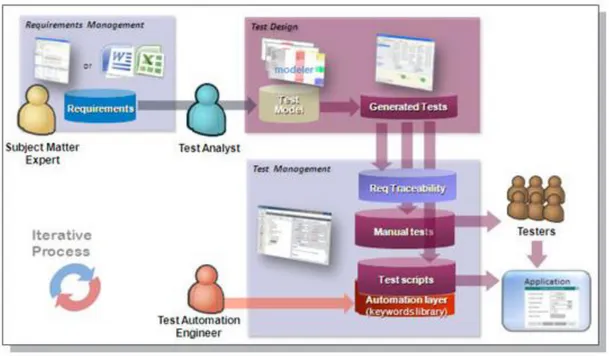
2.6 MBT in Ericsson
In the previous section a brief overview of MBT was given in four stages: Test model design, Selection of Test Criteria, Test Case generation and execution of test cases. A general and detailed MBT working process of Ericsson is given in this section.
In Ericsson, currently Conformiq Qtronic tool is used for MBT. It is an eclipse-based interactive workbench for automated test design. Qtronic is used in Ericsson to generate test suite for functional black-box testing. A SUT is identified initially. All the input documents such as customer requirement specifications, Implementation proposals, functional description documents and functional specifications are read and understood by the test model designers initially for building the models. It is very much important to ensure the compliance of the details in documents with the working system of SUT because the only input for test modeling is the specific set of documents mentioned above. This is a primary prerequisite for any MBT approach.
Once the requirements are clearly understood, they are modeled incrementally using Qtronic. Qtronic uses the combination of UML State Transition diagram and an action language which is a variant of action java (similar to java and c#) as the modeling language. It is called as QML. Conformiq Modeler is used to draw the UML state Transition diagram. The use of diagrams is optional. Whole model can be developed just by writing the QML code. But usage of diagrams is recommended for easy understanding of the functionality of SUT.
Using the model, a set of abstract test sequences is generated. These test sequences can be stored and managed using a test management tool such as HP Quality Center. At least one scripting backend has to be set up in order to generate the test cases. These backbends are specific to the test design configuration. A valid scripting backend JAR file should be provided. Some backbends such as HTML, Perl, TCL and TTCN3 are provided with the Qtronic itself. Any of these backend needs to be pre -configured in order to generate test cases in the desired format.
The generated test sequences or test cases are then reviewed by the experts. If there are any inconsistencies in the test cases or bugs, they are verified again in the model and are modified accordingly. If any modification is done to the model, the test cases have to be regenerated to reflect the changes. This is the process of test case refinement. The test cases should be regenerated even if there is a change in any of the Qtronic settings or any test design configuration.
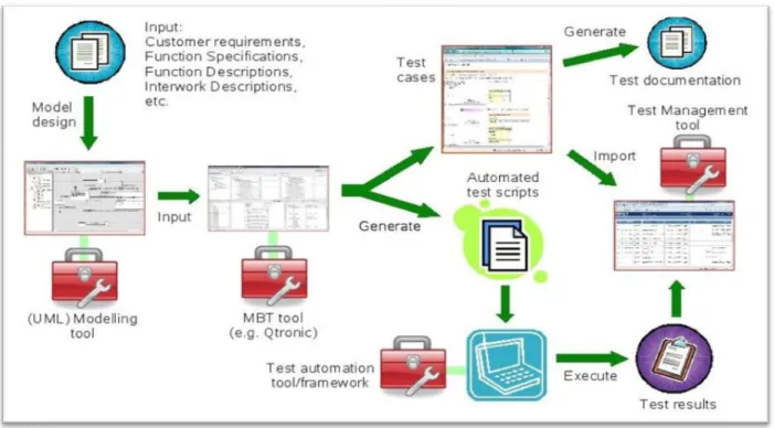
Once a satisfactory model is achieved, the test cases can be exported through the active configured scripting backbends. The exported test cases are used in the test harness in order to convert them to executable test scripts. These scripts are executed on the SUT using a test automation framework and the results are captured. These test results are also stored and managed in the test management tool HP Quality Center. The whole existing process is depicted in Figure 2 [24]. Another brief version of process is given in Figure 3.
Page | 17
Figure 2: MBT process in Ericsson
Page | 18
3. Thesis
This section introduces the problem statement of our thesis work. Then it divides the problem into several sub-problems and finally tries to offer a solution to the bigger problem by solving the smaller ones individually.
3.1 Problem Definition
This thesis work is done in Ericsson. It has started adapting Model Based Testing for functional testing in some of the software divisions of their products. They currently use a tool named Qtronic from Conformiq for functional verification at system level.
In general MBT is not easily adaptable for modelling non-functional requirements of the system. Any new approach for modelling non-functional requirements can be a cost-beneficial and time-saving effort. This thesis is an attempt for finding such an approach.
A wide range of MBT tools are available in market currently, but the suitability and adaptability of the tools to the Ericsson's current test environment has to be determined. Such a process involves taking into consideration many factors such as cost, ease of adaptability, amount of extra effort needed to educate on tools etc. A summary of those related factors for some tools will be helpful in carrying out a decision by the authorities regarding which of the tools can be used.
3.2 Goals
This thesis is mainly about exploration of possibility of applying MBT techniques for non-functional testing in Ericsson, using various MBT tools like Conformiq Qtronic, Elvior Motes and ModelJUnit etc. One goal of the thesis is to do a comparative study of the tools based on some of the factors such as Functionality, Usability, Flexibility, Performance and Pricing in general. Another goal of the thesis is to try and devise a new efficient way of using MBT techniques in modeling and testing the non-functional requirements.
In order to streamline the study, only performance aspect is taken into consideration. A new process is proposed based on the current research carried out in MBT in regular and with respect to the way of working in Ericsson specifically. This proposal is briefly described in the thesis. Based on the proposal, a SUT is identified from the CPP product of Ericsson. The process is applied on the SUT and test cases are generated using different tools. Once if it is found that this proposal works, the same model is used to generate test cases using different available MBT tools in the market, and then a bench marking is done based on several performance metrics of the tools such as ease of automation, test case generation time, cost, limitations, work-arounds, implementation of test harness and availability of easy documentation etc.
3.3 Limitations
Exploring all categories of non-functional requirements for modeling is a huge task. Instead, we chose upon the performance related specifications of the SUT to be modeled as they are of higher priority in any telecommunication system.
Generic UML models cannot be exported to all tools. It is a time-consuming task to model separately the same SUT behavior in different tools in order to prototype. When benchmarking the tools, we
Page | 19 are only considering aspects such as Functionality, Usability and Flexibility. The Performance factor of the tools is considered only for the case studies which we have conducted on two tools only, Conformiq Qtronic and ModelJUnit.
Within the given time limit of thesis, the work is confined to only the generation of test sequences by modeling the behavior of the SUT. The test execution part is out of the scope of this thesis.
Page | 20
4. MBT For Non-Functional Requirements
Testing
Model based testing is basically used for functional black box testing. To some extent it is used to test robustness specifications such as invalid inputs and security related specifications such as authorization and authentication also. Black box testing does only consider the behavior of the SUT and discard the internal structural specification of the system, where as in white box testing the internal structure of the SUT is considered during generation of tests. Ideally efficient test cases are generated if the white box model of SUT is considered.
For testing of non-functional requirements related to attributes such as performance, MBT is not widely used. It is still an area under research. Researchers have been working on the specific ways to use MBT techniques in testing non-functional specifications especially performance testing. In this section some of the difficulties in adapting MBT techniques for performance testing are discussed.
As said earlier, MBT is currently used for functional requirements testing. The general behavior of the SUT can be described by its functional requirements. Hence it is easy to model functional requirements, whereas it is a different case for non-functional requirements. Apart from models describing the functional behavior, other aspects such as analysis models depicting the implementation structures, additional resource requirements for the models etc are required for modeling non-functional requirements. Moreover, since modeling deals with higher level of abstraction, it is difficult to provide reasonable estimates for non-functional properties of the SUT. In that way it is difficult to provide generic solution because it is difficult to specify the non-functional properties of the system at a given point of time.
4.1 Problems in modeling Non-functional Requirements
The problems in testing non-functional characteristics of a system using MBT techniques are discussed earlier. In this section we discuss about the basic issues in modeling of non-functional requirements to generate test cases in context to Ericsson's testing process and based on that propose a solution for modeling them.
The primary obstacle comes in segregation of testing functional and non-functional characteristics. As mentioned earlier, it is a complicated effort to observe behavioral patterns in non-functional requirements of the system. It is closer to understanding of internal implementation of structures, external resources and factors affecting them and branch probabilities etc. One solution can be modeling the system by combining functional and non-functional aspects of the SUT. This can lead to a new type of testing process in the organization. The idea of combining them together for modeling sprout from the concept of Model Driven Performance Engineering [25].
MDPE is the technique derived by Mathias Fritzsche and Jendrik Johannes for Model Driven Development. They observed that iterative Performance analysis during modeling of a system, instead of addressing during the implementation of actual system and make it run, contributed in reducing the total turnaround time of the project and was helpful for on-time delivery with good quality. For this purpose they proposed MDPE as an extension of Model driven Engineering, by combining performance engineering with it. At every phase of incremental development of the model of the system, they
Page | 21 started considering the performance. Based on MDPE, in this thesis we propose a similar process for modeling non-functional requirements using existing functional model developed for MBT.
Secondarily, some of the characteristics testing in Ericsson require additional testing equipment and also manual intervention since it is in the manufacturing of telecom equipment. Those characteristics are difficult to automate even if some can be included in the models. Such characteristics can be tested separately and manually. The idea behind including them in the model even if it is difficult to automate is to generate some special abstract test sequences that may not be thought of while designing the test cases manually.
Performance related characteristics are chosen to be modeled in this thesis to streamline the study. Other related non-functional attributes such as robustness, security etc can be modeled by using standard MBT techniques and also rather it is a common practice.
4.2 New Proposed method for Non-Functional
Requirements Verification Using MBT
Inspired by MDPE, the proposed solution is the inclusion of non-functional requirements (or rather performance characteristics) in the existing functional model of the SUT. This reduces the effort of modeling the non-functional requirements separately. Before including them, logical grouping of the requirements should be done based on the similarity among the requirements. Then a feasibility analysis is done about including these grouped requirements in the existing functional model. This can be done either by including them in the existing states or by creating new states depending on the type of transformations that are required. Once a stabilized model is developed, the test cases are generated. If the chosen requirements could not be logically grouped, or distinct or dependent on any other factors such as requirement of additional tools or involvement of physical interferences etc, those requirements can be modeled separately or tested manually based on the ease of testing. A brief overview of the new process included in the existing process is depicted in the Figure 4.
4.3 Pros and Cons of the New Process
The following are some of the factors on which some of the standard MBT benefits are dependent upon. This section describes the effect of new process on those factors in order to retain the usual benefits.
Time
The time to model is proportional to the total turnaround time of the project. In case of a development project, the modeling of behavior for MBT is developed in parallel to the design and implementation and then the test cases are generated and automated. This reduces the total testing time of the project. Since we are including the non-functional requirements in the existing model and we are not writing any model from scratch, this initially reduces time and effort in basic modeling. Assuming that the functional model already exists for maintenance, the time required for initial modeling is not considered. Only the time required for additional inclusion of non-functional requirements is taken into consideration. Since the new inclusion generates test cases automatically by tool, it will be obviously less than the manual generation time for those test cases. That accounts for the reduction in total turn-around time of the maintenance project.
Page | 22
Figure 4: New Process flow for Verification of Non-Functional Requirement
If the time invested in modeling the system behavior is more than the usual manual analysis and generation of test cases, then it is a hindrance to the overall project time rather than acting as a benefit. In the given process, if the characteristics are totally distinct and cannot be grouped, the time invested in modeling all of them separately may be sometimes more than the manual testing. This process cannot be used in such a scenario.
Quality
In MBT, quality can be measured in terms of the coverage that is done in the model of the SUT behavior. Initially, in the functional model particular coverage criteria can be chosen based on the tool that provides the facility. For example the deeper the look-ahead depth in Qtronic more is the number of more is the coverage and hence more number of test cases are generated.
In the case of this method the approach that followed for modeling to some extent determines the coverage. So quality in this context is independent of the proposed method but purely based on the way the behavior is modeled. Same is applicable for non-functional requirements also.
One of the major advantages of using MBT is to derive key test sequences that are unexpected or missed during manual analysis. Some of the state combinations and branch traversals can give new set of test cases which were non-traditional but are still important.
By including the non-functional requirements in the existing functional model, the chances of new branch iterations will be more and this may result in generation of additional test cases that may not be
Page | 23 usually derived from manual analysis of the requirements. This adds to the better quality of testing in lesser period of time by increasing the coverage.
Cost
The cost incurred in adapting the basic MBT for functional requirements remains unaffected by introduction of this new process for non-functional requirements. Basically, the cost of a testing project is affected by the factors such as the tool selected for the MBT, number of resources working on the new tool and the number of man hours spent on modeling. By introducing the above process the only factor that is affected is number of man hours spent in modeling. But as usual the cost benefits that arose for general functional MBT are applicable for this process too as this process is not introducing any new tools, but only a new method.
Page | 24
5. Tools Overview
This section provides the basic overview of the several tools studied as part of the thesis goal. It is required explore on different tools available for MBT in the market and do a comparative study on the tools based on the factors such as Functionality, Usability, Flexibility, Performance etc. The performance factor of the tools Qtronic and Model JUnit is discussed in Chapters 7 and 8 where the case-studies are briefly discussed. Following sections give a brief overview on the work-flow of different MBT tools like Conformiq Qtronic, Model JUnit, and Elvior Motes etc.
5.1 Qtronic
Qtronic is the automated test design tool from Conformiq, which automates functional tests of the System and Software. It facilitates the System Tester by automatic generation of human readable test cases from the expected system behavior of the System under Test (SUT). A high-level system model is given as input to the tool. The tool generates a set of test cases calculated mathematically from the given model. The test cases later can be exported to customizable formats such as TCL, TTCN-3, and HTML etc.
5.1.1 Workflow
The following diagram shows the workflow of Qtronic tool.
Figure 5: Workflow of Qtronic
5.1.1.1
Modeling SUT
The first step as in every MBT tool is a clear understanding of specifications. The experience and knowledge about SUT behavior of a tester should help him to visualize the transitions based on the understanding of specifications. The next step is to model those specifications. Today widely used modeling tool is UML 2 whose syntax is based on diagrams. UML supports 13 different types of diagrams such as use case diagrams, class diagrams, sequence diagrams and state transition diagrams etc. These diagrams are basically categorized as structural and behavioral diagrams. Since MBT is mainly based on
Page | 25 the consideration of whole system behavior, Qtronic uses state machine diagrams, class diagrams and component diagrams depending upon the platform used for modeling as input. The output generated test cases can be visualized in the form of message sequence diagrams. There is no specific diagrammatic representation of data in order to manipulate the actions. Hence a programming language usage was necessary. UML2 facilitates the textual notation of the actions in the transitions through a language called action language. Conformiq uses the modeling language called QML (Qtronic Modeling Language) which is a combination of state transition diagrams and an action language which is a variant of Java.
Here is a sample of Qtronic model which contains the action code and corresponding state machine. The action code is written in some file called 'Sample.java'.
Table 1 : Sample QML code
record Msg{ } system {
Inbound in: Msg ; Outbound out: Msg ; }
class NewClass extends StateMachine {} void main ( )
{
NewObject = new NewClass( ) ; NewObject.start( );
}
The first line signifies the message type that is equivalent to record which is a mix of data types which can encapsulate both data types and functions. The next section defines the external interface of the system. The system block contains the declarations of the Inbound and Outbound interfaces or ports. The identifiers in and out are the names of the interfaces. The data that falls after the semicolon are the records that are allowed through those ports. The next block is a definition of class whose name is
NewClass. This class inherits the concept of being a state machine. This class doest have any content as
of now. The next block is the main block from where actual program starts. In the main block only a new instance of the class NewClass, NewObject is created. Using the start () action the NewObject is being executed inside the model.
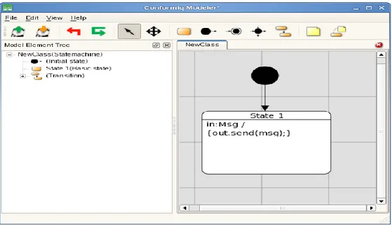
This model is still incomplete. Here we need to associate a state machine to the code. The corresponding state machine is described in Figure 6 which can be drawn by using the Qtronic modeler. It shows the functionality that is running inside the state. The associating link between the code and state transition diagram is done through a test design configuration which will be discussed later in this section. The important rule for the association is that the state machine name should be same as the class name. This links the state chart to the class. In this case the xmi file is named as 'Sample.xmi'.
Page | 26
Figure 6 : Modeler Provided with Qtronic
The black circle above represents the 'initial state' of the machine. The arrow represents the transition to state 'State 1'. The code inside the state is the internal transition logic within the state. It represents the activity being trigged to be done when the system is in this state 'State 1'. 'in:Msg' denotes the triggering of action when the message 'Msg' is arrived inside thought the port 'in'. The code in the braces represents the action to be taken after the trigger. '/' is used to separate the trigger and action. The line ‘out: send (msg)' represents the action. 'msg' is the default variable used to handle the message in that state. This contains the record of the type Msg. The line represents sending of the message outside through the port ‘out’.
To summarize the functionality, the system first creates an instance of class New Class which is the object New Object. The object is executed and goes from initial state to 'State 1'. In this state the objects wait for incoming message through port 'in'. Once the message is received it sends the message through the 'out' port and the object still remains in the state.
5.1.1.2
Test Configuration and Generation
Here is the sequence of steps for test configuration and test generation process in Qtronic.
1. After installing Qtronic plug-in in Eclipse, switch to Qtronic perspective by selecting Window > Open Perspective. Now select Qtronic.
2. Select New > Qtronic Project. This will also create a Test Design Configuration (DC). The DC contains the settings for coverage criteria selected and configured scripter plug-ins.
3. Import the model files Sample. java and Sample.xmi into the project.
4. Click 'Load model files to Computation Server' to load the model files into computation server. 5. Generate test cases by clicking 'Generate Test Cases from Model'. This generates the test case
with sequence numbering in the 'Test case List' window. By clicking on each of the test cases a sequence diagram of the test case is seen in 'Test case' window.
Page | 27 Test cases can also be rendered by configuring a scripting back-end. Script back-end can be configured by selecting the test design configuration (DC) and then clicking New > Scripting Back-end. Once it is configured, click on 'Render All Test Cases' to render in the format specified by the scripting back-end.
5.2 Motes
Motes [5] [9] [10] [11] [12] is a MBT tool that generates TTCN-3 test-cases from the Implementation under Test (IUT), whose behavior is modeled as Extended Finite State Machine and by use of some supportive TTCN-3 files. These files consist of Test Data, Test Data types, Context Variables and Interface specification (Message Types and Communication Ports) of the IUT. The generated TTCN-3 test cases can be executed using any TTCN-3 supportive tool to check the IUT behavior.
5.2.1 Workflow
The principle work flow of the Motes which is used to generate the test cases from the IUT behavior is as follows:
Figure 7: Workflow in Motes [12]
5.2.1.1
Modeling IUT
The model of the IUT which defines its functional testable behavior consists of the EFSM Model, Context variables, Communication Message Types definitions and Communications Ports Definition.
Page | 28
EFSM Model
It defines the behavior of the IUT by means of the UML state machines. Motes don’t have own modeler for developing EFSM models. Motes currently supports EFSM models from third party UML case tools such as Artisan Studio and Gentelware Poseidon. In these tools IUT behaviors are modeled as flat state machines. Parallel and Hierarchical state machines are currently not supported. These models are then exported in XMI 2.1 format. These XMI files are used by Motes as one of its inputs for test generation. In the next versions, Motes can accept XMI files from other UML case tools also. According to the UML specification, EFSMs do not have any formally specified action language for representing guard conditions, input events and actions on the transitions. To define the transitions in the UML state machines a formal transition language known as Motes Transition Language is used.
Context Variable
The context variables are the variables which are defined in the TTCN-3 files and are used in EFSM models. These variables are used to define the state information as well as to control the state transitions in EFSM model.
Interface Specifications
These specifications define the interface of the IUT with the test environment. It consists of the Input/output ports and their respective definitions and is declared in TTCN-3 files. The port definition consists of the port behavior and message types that accept while communicating with the external world through the system’s boundary. The port behavior comprises of the direction in which port operates, such as Input, Output or both and its message types. Message type defines the data types accepted by the port.
5.2.1.2
Prepare Test Data
This test data defines the stimuli which are supplied to IUT model to generate TTCN-3 test cases. It is prepared manually by the user in the form of TTCN-3 files. These files consist of TTCN-3 templates filled with the respective data for the corresponding message type accepted by the IUT ports.
5.2.1.3
Importing Models and Test data
Models and the associated Test data which are prepared in the previous steps are imported to the Motes tool to generate the TTCN-3 test cases. Next, the user must define a new resource set or re-use existing ones. Importing of the models and test data to Motes is performed through resource set. A resource set performs the task of linking together the relevant input resources required by the test generator. User is required to modify resource set accordingly, whenever there is any change in the model or /Test data.
5.2.1.4
Defining Test Coverage/Goal
Motes use the test coverage specified by the user on the model structure elements (transitions and states) to generate the test cases. The coverage criteria provided by Motes are as follows:
Selected Elements (states/transitions)
Page | 29
All N-Transition Sequences
Selected Elements (selected states and transitions): A coverage criterion is used to define test coverage
for the list of EFSM transitions and states. It is possible to create ordered and unordered sets of coverage elements and to define how many times each coverage element or a subset of the elements should be covered. It is possible to cover complex test scenarios using ordered sets of coverage items. There are two types specified for this purpose: set and list. Set consists of unordered test elements, whereas list consists of ordered set of test elements.
All Transitions: This test coverage defines that the test generator should find the test case that covers
all of the transitions in the EFSM at least once.
All N-transition sequences: It is a test coverage criterion that allows some long and exhaustive test
cases which cover all subsequent transition sequences of n transitions in EFSM model to be created. MOTES allows N to be 2 or 3.
5.2.1.5
Selecting Test Generation Engine
Motes support two engines for the test case generation:
Model checking engine
Reactive planning tester engine
Model Checking Engine: It is the off-line test generation engine that supports test generation of the
deterministic IUT. It utilizes the UPPAL CORA Model checker to identify the test sequence from the IUT model. Generated test cases always comprise of the sequence of events to test the modeled IUT behavior. It is operated in two modes.
A. Iterative: It is greedy mode of test case generation, which is operated in iterations to identify the
sub-optimal test sequence. This mode is preferred to use when there is a constraint of low memory.
B. Non-Iterative: It is the optimal mode in which the engine identifies the whole test sequence of
minimum length required to achieve the set test goals.
Reactive Planning Tester Engine: This engine operates in both on-line and off-line mode. It generates
the test cases for deterministic and non- deterministic IUT.
5.2.1.6
Generating the test cases
Once the above steps are completed, user proceeds for the test generation and the test generator does the rest. The TTCN-3 test cases or reactive planning tester TTCN-3 code are generated under the current resource set on the basis of selection of the test generation engine. The generated TTCN-3 files can be imported to any supportive TTCN-3 test tool and run against the IUT.
5.3 MaTeLo
Markov Test Logic (MaTeLo) [4] is an off line model-based testing tool provided by All4Tec [4]. MaTeLo has its own modeler and the tests are exported in textual notation. MaTeLo uses Markov Chain models (Refer Terminology) and therefore focuses on test control oriented systems. MaTeLo facilitates exporting formats for automatic and manual test execution. It is only supported in Windows platform.
Page | 30 MaTeLo is divided into two separate programs, Usage Model Editor and Testor. The Usage Model Editor uses the Markov Chain Usage model for modeling notation. The usage model can be viewed as a finite state machine extended with probability numbers. It is not extended with programming languages but does accept variables, Scilab/Scicos functions, and Matlab/SimulinkError! Reference source not found. ransfer functions, extending the model for simulating expected results. While the use of these variables and functions limits the model’s complexity, they are not as effective as programming languages. The lack of a programming language extension sets limitations on present data flow models. MaTeLo accepts many kinds of models as inputs via the MaTeLo converter. These inputs are important for the reuse of existing models. While MaTeLo only provides deterministic models, these can include asynchronous inputs.
Figure 9: MaTeLo Testor Window Figure 8: MaTeLo Modeler Window
Page | 31 MaTeLo Testor takes the model as input and generates a test suite. Testor validates the model before usage. Validation means checking modeling errors like unattainable states. Test generation facilitates the user with the selection of any of the configurable options: random, boundary value testing, most probable route, state coverage and transition coverage. MaTeLo also provides time limits.
MaTeLo cannot execute tests itself. However, it is possible to export test suites into HTML, TTCN-3 or Test Stand formats. TTCN-3 and Test Stand are used for automatic test execution, while HTML can be used as documentation for manual testing. Test Stand is a test management tool created by National Instruments. During the testing process, Report Management is used for making a report of test campaign monitoring. Report Management has the additional feature of presenting pleasing graphical figures of the testing process.
Probability numbers is the main idea behind the Markov Chain. MaTeLo is therefore a good choice for control-oriented testing.
5.4 ModelJUnit
ModelJUnit [2] [14] is a set of open source libraries that consists of a set of JAVA classes for model based testing. The libraries are designed by Dr.Mark Utting. It aims at generation of test sequences from the FSM/EFSM models written in JAVA and measures different model coverage metrics. Model JUnit has the features to automate both test generation and test execution.
5.4.1 Workflow
5.4.1.1
Modeling SUT
In ModelJUnit, FSM model is written as a JAVA class that implements various interfaces defined in the library such as
FsmModel: It is the basic interface which every (E) FSM model class must implement for model
based test generation.
TimedFsmModel: It is a special interface that extends the functionality of FsmModel interface and
builds the FSM that uses the ModelJUnit timing framework.
The model class created using interfaces shown above must have the following methods:
1. Object getState()
This method returns the current state of the model, which typically is an Object. It performs the task of mapping the internal state of the EFSM model to the actual visible state represented in the model by the model designer.
2. void reset(boolean)
This method performs the task of resetting the SUT to the initial state or creating new instance of SUT class. It is used typically in online testing, where we need to reset SUT to the initial state. Default value of Boolean parameter is ‘true’. The Boolean parameter with value ‘false’ is used when operations in SUT are less responsive or when we want to generate only the sequences with the current EFSM model.
Page | 32
3. @Action void name()
These types of methods are used to define the actions in the EFSM model. These actions change the state of the SUT. There can be more than one action methods defined in one EFSM model. It requires only the @Action annotations and no parameters. Each action method can exist with or without guard. This guard decides the enabling/disabling of the action to be called during test sequence generation. In case of no guard, the library provides the default guard that always remains true.
This method contains sequence of adapter code which tests the particular behavior of the SUT .The adapter code calls one or more SUT-defined methods and check the correctness of the results on the basis of the response from SUT. Testers have to specify the test data in methods called on SUT.
4. boolean nameGuard()
It defines the guard for the action methods defined in the model. This method always returns boolean. The method name must be same as the action name (for which guard is defined), with the added word ‘Guard’ at its end.
Table 2 : Sample ModelJUnit model code
public class FSM implements FsmModel { private int state = 0 ; // 0 . . 1
public FSM( ) { state = 0 ; } public String getState ( )
{ return String.valueOf (state) ; } public void reset (boolean testing ) { state = 0 ; }
public boolean action0Guard ( ) { return state == 1 ; }
public @Action void action0 ( ) { state = 0 ; }
public boolean action1Guard ( ) { return state == 0 ; }
public @Action void action1 ( ) { state = 1 ; }
public boolean actionNoneGuard ( ) { return state != 1 ; }
Page | 33
public @Action void actionNone ( ) { }
}
The java class is equivalent to the graphical notation depicted in Figure 10 below:
Figure 10: ModelJUnit Generated Graphical EFSM Model
5.4.1.2
Test Configuration
In order to perform testing on the SUT, testers have to specify following parameters: o Test Algorithm
The test generation algorithm explores the FSM graph of the model, and generates the test sequences for it. Model JUnit provides varieties of the traversal algorithms such as
Random tester: This algorithm performs random walk around the generated FSM graph. During the
walk-in, in each state it randomly selects one of the enabled out going transitions from the current state towards any next possible transition.
Greedy tester: It does a random walk around the FSM graph and during walk, in each state it gives
fondness to the unexplored outgoing transitions. It is efficient as compared to Random Tester, in traversing the graph.
Look ahead tester: Look ahead tester algorithm works somewhat similar to Greedy Tester, but provides
more refined options available, such as look ahead depth and several other parameters. Some of the parameters specify to look ahead in the several available transitions to identify the possibility of reaching the unexplored areas and then it tries to reach those states. One more parameter is ‘Maximum
Test Length’ that shall be set in order to control the search of graph for test sequences.
o Test coverage
Model JUnit defines the coverage metrics for measuring the coverage of the model designed by the tester. It is generally a good practice to use these metrics to check the efficiency and quality of the
Page | 34 model that has generated considerable amount of test sequences to cover the majority of the behavior of the SUT. These Coverage Matrices are:
State Coverage: This coverage shows the number of times each state of the model has been entered in
the generated test sequences. A call to the reset action will increment the count for initial state. The count for target state will be incremented on the basis of transition. It shows the comparison details between the number of states covered and the total numbers of states defined in the model.
Transition Coverage: It defines the number of transitions that are covered in the generated test
sequences. It also shows the comparison details on the number of executed transitions against total numbers of transitions defined in the model.
Action Coverage: Action coverage defines the number of distinct actions that are covered in the
generated test sequences. It shows the comparison details on the number of distinct actions visited / Total numbers of actions defined in the model.
Transition Pair Coverage: This coverage shows the number of transition pairs that have been tested in
the test sequences generated from the model. It shows the comparison details between the numbers of transition pairs tested and total numbers of Transition Pairs defined in the model.
5.4.1.3
Test Generation
It is last step that leads to generation of test sequence from the model and defined test configurations. There are two modes of test generation.
Online: Model JUnit is usually used for on line testing, where the tests are executed on the SUT, as
they are generated by the model. In on line testing, users have to integrate the ModelJUnit code with the JUnit API. So that each time when the user run your JUnit test suite, you will generate a suite of tests from your FSM/EFSM model of ModelJUnit. Also, the @Action... methods in the model class will include code to interact with the methods of SUT; it is required to check their corresponding return value, and the current status of the SUT. In this process, when user runs the JUnit tests, the corresponding model is used to generate a sequence of @Action... calls and test the SUT.
Offline: In this mode only messages are generated by model execution. The generated message is
the test sequence in from (Initial state, Action executed, Target State) .These generated messages could be saved in a file and used as a test script for later test execution (offline testing).
5.5 MBT Tigris
MBT Tigris [6] is an open source tool which has been designed in JAVA, for generating test sequence from the SUT models. These test sequences can be rendered in Java or Perl platforms. It can be operated in both GUI and command mode and supports generation of both online and offline test sequences. Tigris can be integrated with other tools that understand web-services and also it can support requirement traceability.
5.5.1 Work flow
The basis workflow that generates the test sequence for the SUT is depicted in the flow graph of Figue11.
Page | 35
Figure 11: Workflow of MBT Tigris
5.5.1.1
Modeling SUT
The system behavior of the system is modeled as Finite State Machine or extended Finite State Machine. The tool doesn't have its own modeling editor. It depends on the open source graphical modeling language tools such as Yed. There are certain guidelines that the user has to follow to model SUT behavior:
1. FSM or EFSM model has to be the graph or digraph.
2. Every graph must have the vertex with label ‘Start’. It defines the start point of the graph.
3. There shall be no Stop or Exit points in the Graph. Modeling doesn’t imply to the UML specifications.
4. The model should use proper naming conventions defined in the online manual for the edges and vertex.
5. The generated graph must to save in graphml format.
5.5.1.2
Test Configuration
This is the next step after the modeling of the SUT. The tool uses the graphml file supplied by the graph editor. User specifies the following parameter for generating test sequence as:
1. Test Generator 2. Stop Condition
Page | 36 Test Generator
It specifies the possible test sequence generator algorithms. For a particular test suite user can select only one algorithm at a time. Possible test generators are:
Table 3: List of Generators for MBT Tigris
GENERATOR DESCRIPTION
A_STAR This algorithm works well with the small models to identify the shortest possible test sequence with complete coverage. If, it is employed in the large models the downside is that it takes lots of CPU computation time to generate test sequences.
RANDOM It works well with the considerable larger model and generates test sequence on the basis of random selection of out edges from the existing vertex and then it repeat the process till the stop conditions are reached.
SHORTEST_NON_OPTIMIZED This algorithm works intermediately between A_STAR and RANDOM, with generating short sequences from larger models.
Stop Condition
In this tool the model doesn’t have stop or exit points. In order to provide a stop to the test sequence generation, stop condition is used. These are shown in the table below.
Table 4: List of Stop Criteria for MBT Tigris
STOP CONDITION DESCRIPTION USAGE VALUE
VERTEX_COVERAGE It specifies the percentage of the vertices covered in the model
An Integer between 1-100
REACHED_EDGE The edge at which the test sequence will stop
Label used to represent edge
NEVER The test sequence generation shall never
stop/Halt
N/A
REQUIREMENT_COVERAGE Specification for the percentage count of the requirement covered in the generated test sequence
An Integer between 1-100
REACHED_VERTEX The vertex at which the test sequence will stop
Label used to represent vertex
TEST_DURATION The amount of time specified till the test generation will be performed
An Integer that specify time in seconds REACHED_REQUIREMENT It signifies that test generation will run until
the specified requirement is reached
Requirement Tag is used to specify the


![Figure 7: Workflow in Motes [12]](https://thumb-eu.123doks.com/thumbv2/5dokorg/4687027.122827/27.918.201.797.420.831/figure-workflow-in-motes.webp)


