Ray traced gaming, are we there yet?
Yvonne Schudeck
School of Innovation, Design and Engineering Mälardalen University
Bachelor Thesis in Computer Science 2016-02-17
Supervisor: Afshin Ameri Examiner: Thomas Larsson
2
Abstract
Advances in hardware acceleration has resulted in development of a variety of hardware accelerated ray tracing libraries. The purpose of this bachelor thesis is to investigate if a simple ray tracer, based on a hardware accelerated ray tracing library, can achieve acceptable frame rates in rendering simple 3D game-related environments. Games are often associated with fast rasterization-based rendering techniques, but rasterization is limited where instead ray tracing holds many advantages.
Background research was done to gain knowledge about related work, state-of-the-art in ray tracing and available hardware accelerated libraries. By using a method similar to Kanban and Scrum [36], the implementation was split up into different tasks, prioritizing the tasks of implementing basic functionalities of a ray tracer. A simple ray tracer was implemented based on the chosen library Embree, a framework developed at Intel Corporation.
Results show that the scenes rendered in lower resolutions (800 x 600) are good candidates for having a stable frame rate of 30 FPS, which is not enough in order to render a real game. The standard of games today require high resolution (full HD 1920 x 1080) and complex scenes. Earlier studies show that Embree has potential of higher performance and looking back the performance of real-time ray tracing has improved, but is still limited to low resolutions and simple lighting and shading models.
3
Sammanfattning
Framsteg inom hårdvaruacceleration har resulterat i att en rad olika hårdvaruaccelererade bibliotek för strålföljning utvecklats. Syftet med denna kandidat-uppsats är att undersöka om en enkel strålföljare, baserad på ett hårdvaruaccelererat bibliotek för strålföljning, kan uppnå acceptabla bildfrekvenser vid rendering av enkla spel-relaterade miljöer i 3D. Datorspel förknippas ofta med snabba renderingstekniker. Rasteriseringsalgoritmen är dock begränsad där istället strålföljning har många fördelar. En litteraturstudie gjordes för att få kunskap om relaterade arbeten, state-of-the-art i strålföljning och tillgängliga hårdvaruaccelererade bibliotek. Genom att använda en metod som kan liknas vid Kanban och Scrum [36], blev implementationen uppdelad i olika uppgifter (eng. tasks), där implementationen av grundläggande funktioner av en strålföljare hade högsta prioritet. En enkel strålföljare implementerades med det valda biblioteket Embree, ett ramverk som utvecklas hos Intel Corporation.
Resultaten visar att scenerna som renderas med lägre upplösningar (800 x 600) är goda kandidater för att uppnå en stabil bildfrekvens med 30 bilder per sekund (eng. frames per second), vilket inte är tillräckligt för att rendera ett riktigt spel. Standarden hos spel idag kräver hög upplösning (full HD 1920 x 1080) och komplexa scener. Tidigare studier visar att Embree har potential för högre prestanda och tidigare resultat visar att prestandan av interaktiv strålföljning har förbättrats, men att den fortfarande är begränsad till låga upplösningar och enklare belysningsmodeller.
4
Table of contents
Abstract ... 2 Sammanfattning ... 3 1. Introduction ... 5 1.2 Problem definition ... 5 2. Background ... 62.1 Ray tracing in games & related work ... 6
2.2 Hardware accelerated ray tracing ... 9
3. Methods ... 11
4. Theory ... 12
4.1 The ray tracing algorithm ... 12
4.1.1 Illumination model ... 13
4.2 Acceleration structures ... 15
5. Embree ... 16
6. Implementation ... 18
6.1 Initial preparation process ... 18
6.2 Programming the application ... 19
7. Results ... 22
8. Alternative experimental setups... 26
9. Discussion ... 27
10. Conclusions ... 28
10.1 Future work ... 29
5
1. Introduction
In computer graphics there are a variety of different techniques used to render images. Ray tracing is one of them and it is well known for being computationally expensive. Ray tracing is capable of simulating physics of light such as shadows, reflections and refractions and is used to render photorealistic images, as well as animations and special effects for movies (i.e. Pixar’s ‘Cars’ animation movie[1]). In comparison to other rendering algorithms in which light effects may need a lot of workarounds (i.e. reflection maps, shadow maps, etc.), ray tracing is far more physically accurate. Because of this, ray tracing is also used as a research tool in scientific research to simulate physics of light, as in the paper by Chan et al. where ray tracing techniques are used for simulation of photon trajectories in a curved space-time or as in the paper by Yapo and Cutler, where they presents the use of ray tracing amongst other techniques to render Lunar Eclipses [2], [3]. The disadvantage of using ray tracing is and has always been its performance, being computationally expensive, detailed images can take hours or even days to render [4]. To use it in real-time applications has not been an option and instead other faster rendering techniques are used, such as those based on rasterization [5]. Several researchers have worked with speeding up the algorithm by parallelizing it combined with using different algorithms and data structures to accelerate it on CPUs as well as on GPUs, which has led to the development of several hardware accelerated ray tracing libraries out on the market today, by both GPU and CPU distributors.
With these new technologies and advances the need for a study on such systems and libraries is growing and maybe finally we are able to answer the question: Is real-time ray tracing available for the masses soon?
1.2 Problem definition
Computer games are a big part of moving the research forward in computer graphics [6]. This is a study to investigate if a simple ray tracer, based on a hardware accelerated ray tracing library, can achieve acceptable frame rates in rendering game-related environments. In other word, we try to answer the following question:
Can hardware accelerated ray tracing libraries achieve acceptable frame rates on simple 3D game environments?
An acceptable framerate is 30 FPS (frames per second) [7]. A game-related environment would mean that the scene rendered need to have similar structure as in a game, such as scenery with multiple static or dynamic objects.
In their paper from 2006, Friedrich et al. states that ray tracing performance isn’t ready to compete at the current market for games [6]. But with new advances in both hardware,
6 algorithms and different acceleration structures, having new several hardware accelerating ray tracing libraries available there's a need to study this.
2. Background
Up until recently ray tracing hasn’t benefited from special purpose hardware (i.e. GPUs), resulting in lower frame rates. But with advances of both CPUs and GPUs, hardware acceleration structures, parallelization and advances in algorithms, it's now possible to get higher performance [8]. Ray tracing applications are no longer limited to offline performance (i.e. [9]), but are still very limited to low resolutions, high-end hardware and simple shading [8].
2.1 Ray tracing in games & related work
With ray tracing techniques advancing, the study of using them to render games is of great value. Rendering computer games has always been associated with rasterization techniques, since it makes complex interactive scenes possible to render at a very low cost and still give an acceptable visible result [5]. But rasterization is limited due to its algorithm, where ray tracing instead holds many advantages. Ray tracing computes recursive visibility queries, globally showing how light hits an object with regard to surrounding objects (Shadows and reflections etc.). Rasterization on the other hand shades objects locally and needs extra support by pre-computing shadow and reflection maps to show the global result, since it’s not included in the rasterization pipeline [6]. Another issue when it comes to rasterization is when having dynamic lights and transparent objects, using shadow mapping (which is the most common algorithm used in rasterization to compute shadows), each shadow cast by transparent objects is often part of a texture, resulting in dynamic light not casting shadows “naturally”, as they would using ray tracing [10].
When measuring performance of a real-time application, frames per second is one known measurement. Games normally run at 30 to 60 FPS, or even 120 FPS using the latest hardware. Frame rates are linked to monitor refresh rates, which in most computers today is 60Hz (1 Hz is one cycle per second) and frame rates evenly divided by the refresh rate would show a good result. E.g. if a monitor’s refresh rate is 60Hz and the game is run in 30 FPS, then each of the 30 frames would be displayed twice every one-thirtieth of a second [11], [12]. If the framerate would drop below 30 the game would start to look “choppy” [12]. At early days of the game industry, many games were frame-rate-bound. This means that the game would run on a fixed frame rate. From the developers’ point of view the time intervals between the frames were fixed and therefore the developer could use the frame number as a measure of time. The problem with this design was that any try for increasing the frame rate would mean speeding the animations up. Modern games do not use such algorithms and instead use the actual time between the frames to make their calculations for animated objects and physics. Therefore, the games are time-bound and could produce accurate animations at any frame rate. Some games also lock their framerate (to 30 FPS etc.) to ensure the players have a smoother gameplay, instead of
7 having a high frame rate that dips to lower frame rates, since it would break the focus that the player has whilst playing the game [11].
Schmittler et al., in 2004, implemented a ray tracing engine using OpenRT for the use of rendering the game Quake 3: Arena by Id-Software. They aimed to fully support the current effects of Quake 3, but also functionality such as collision detection through ray tracing. The ray tracing features incorporated were effects of glass being reflective and refractive, mirrors, per-pixel shadows and colored lights, to mention a few. The following figure, figure 1, shows screenshots of the game rendered at a resolution of 640 x 480 pixels using a PC cluster, with around 5-20 FPS [13], [6].
Figure 1: Four different screenshot of the game Quake 3 rendered using a ray tracing engine (figure taken from [13]).
Oasen by Schmittler et al. is a game designed to use real-time ray tracing as the core rendering engine. The main features included simulations of a changing sky with procedural clouds and stars, in day and night situations, but also animated objects in the environment such as swimming fish [13], [6]. Images, shown in figure 2, were rendered using the same set-up as the ray tracing project used to render Quake 3 and authors of the paper [13] state that interactive frame rates was reached.
Figure 2: Screenshots from the game Oasen were rendered using a PC cluster at a resolution of 640 x 480 pixels (screenshots taken from [13], [6]). Leftmost screenshot is a good example of the procedural clouds and the reflections of them in the water, the second screenshot shows some swimming fish in the water and the third picture from the left is a screenshot during night in the game.
At Intel Corporation the research is moving forward. During 2008 Intel worked with converting the game Enemy Territory: Quake Wars created by Id-Software to make use of ray tracing to render. The author refers to the project of rendering Quake 3 using a ray tracer in 2004 and shows a slight improvement of performance rendering Quake Wars of 20 - 35 FPS at a resolution of 1280 x 720, using Intel’s at the time latest quad-socket with 2.66 GHz processor in each socket [10].
Recent work has shown that real-time performance using commodity GPUs like Nvidia GeForce 8800 GT is possible. At a resolution of 1024 x 1024 pixels in scenes with 66 to
8 871 thousand triangles a result of 43 - 30 FPS was reached using a CUDA-based1 ray tracer
implemented by Shih et al. All scenes were rendered using primary rays only and simple shading [9].
Aila and Laine implemented optimized variants of the fastest GPU “trace” kernels in CUDA and compared the measured performance against the upper bound of performance of the kernel using a custom simulator on a chosen NVIDIA GPU. The average performance was measured in scenes ranging from 54 to 282 thousand triangles at a resolution of 1024 x 760 pixels using NVIDIA GTX2 [16]. Counting primary rays’ one scene achieved 75 - 142 million rays per second which according to Ludvigsen and Elster’s paper [4] roughly translates to 95 - 180 FPS. This is in fact a high frame rate, but casting only primary rays to display a scene won’t make any use of the benefits of ray tracing, which instead isn’t good at all. Ludvigsen and Elster implemented a ray tracer using NVIDIA OptiX framework, which also makes use of CUDA, to see if similar results were possible to reach using the same scenes, resolution and hardware from the same generation. Their implementation resulted in being 3-4 times slower in comparison to results presented in [16] and they state that OptiX has potential of much higher performance [4].
In early 2015 Nah et al. implemented a CPU-GPU hybrid architecture for ray tracing dynamic/animated scenes. They were able to render scenes with 92k triangles to 1.6m triangles with a frame rate of 264 to 36 FPS at a resolution of 1920 x 1200 pixels using an asynchronous BVH (Bounding Volume Hierarchy) construction on a CPU together with dedicated ray tracing hardware [17].
In a paper published in 2014, two different frameworks for hardware acceleration were compared by creating three different diffuse-only path tracers: A scalar renderer with the Embree single-ray SIMD kernels, a parallel renderer written with ISPC (Intel SPMD Program Compiler) and the Embree hybrid packet / single-ray SIMD kernel and an OptiX renderer. The comparison were done using very complex scenes ranging from 800 thousand triangles to 12.7 million triangles at a resolution of 1920 x 1080 pixels. When measuring rays per second their so called Embree Hybrid reached 59 - 136 million rays cast per second, OptiX with 72 - 44 million rays cast using TRBVH (Tree let Reordering BVH) and 80m - 41m using SBVH (Split BVH) and lastly the Embree Single-Ray with 70 - 45 million rays cast using a BVH with spatial splits [18].
Research on improving efficiency and new releases of many-core hardware which makes use of parallelism to accelerate graphics operations, are big contributors in gaining performance [10]. In order to achieve real-time performance, hardware acceleration is required.
1CUDA - abbr. for "Compute Unified Device Architecture" is a parallel computing platform and
9
2.2 Hardware accelerated ray tracing
To speed-up different tasks in a ray tracer, mostly referring to the intersection tests (when the ray hits or doesn’t hit an object in the scene), different acceleration structures can be used. Three well known algorithms to accelerate ray tracing are uniform grids, Kd-trees and BVHs, see section 4.2 for a brief description. No single technique is optimal to use in all types of scenes, but both the Kd-tree and BVH yield a similar performance on the CPU when they are built in a top-down fashion and overall they’re well suited for inhomogeneous scenes, whereas uniform grids perform better when scenes have homogenous object distribution in space [19], [20].
With ray tracing performance improving, reaching for real-time, acceleration structures need research in order to make them effective in interactive applications. In animations, where geometry change each frame, the current data structures would need to be updated using either on-the-fly restructuring or rebuilding strategies [21], [22], [23]. Wald investigated how to build SAH-based (Surface area heuristic) BVHs by using techniques similar to successful techniques used to quickly build Kd-trees. Rebuilding the structure, tracing the rays (with shading and shadows) and displaying, gave a result of 5-10 FPS in an animated scene in which a dragon mesh exploded [23].
Traditionally ray tracing computations have been done on the CPU, but with improving computation power and high memory bandwidth on the GPUs, having several hundred or even thousands of cores, they’ve also become attractive to use in compute-intensive applications [4], [9]. Purcell was the first to publish a paper on a ray tracing algorithm that was mapped on the GPU [24]. Research has shown that accelerating on the GPU holds both possibilities and limitations. A big difference between the CPU and GPU is the fact that the GPU cannot do branching efficiently (i.e. refraction) and Carr et al. stated that a GPU based ray tracer which shares workload with the CPU will have a CPU-GPU communication bottleneck [4], [25]. As of today there's a lot of research on improving different acceleration techniques on the GPU, such as the stackless algorithm called Kd-restart and Kd-backtrack created by Foley and Sugerman which makes it possible for the GPU to use a Kd-tree without needing a stack (which is required by the normal Kd-tree) since the GPU poorly supports it [26].
Ray tracing is well-known for its parallel nature, where each ray may be traced independently, which makes it a good fit for multicore and multiprocessor architectures [4], [9]. Therefore it might seem like a valid choice to try to use GPU Computing techniques to benefit from many parallel processing cores available on today’s GPUs. The idea of GPU computing is to make a CPU and GPU co-work with various workloads; the host part of the program runs on the CPU while the computationally demanding part is accelerated by the GPU. One difference of a CPU and GPU is how they process tasks, a CPU consists of few cores optimized for sequential serial processing while a GPU on the other hand consists of a parallel architecture in which there are thousands of smaller cores designed to handle multiple tasks simultaneously [27], [28]. In a CUDA program, the GPU is treated as a
10 coprocessor to the CPU. The parts of the program that is executed regularly on different data independently can be isolated into a function called a kernel and executes on the GPU as multiple different threads. When a kernel is executed, every thread is organized into a grid of equal-sized blocks, where they can synchronize at a specified point and cooperate with fast shared memory [4].
Today a variety of ray tracing libraries, engines and systems exist (e.g. OptiX2 and
Embree3), where most tackle with problems not easily solved using rasterization-based
rendering systems [8]. Many ray tracer APIs and engines available are developed by open source communities, enthusiasts and researchers, some of them outdated (e.g. OpenRT [31]). The libraries and engines developed by large companies, like OptiX developed by Nvidia or Embree developed at Intel, are popular on the market and up-to-date.
FireRays is a GPU intersection acceleration library. This was developed by AMD to help developers get the full benefit of AMD GPUs and CPUs or APUs (Accelerated Processing Unit). It has a C++ API for creating scenes and performing asynchronous ray intersection queries. It is currently based on OpenCL and being so, FireRays support execution on all platforms conforming to the OpenCL 1.2 standard, which means that FireRays isn’t bound to AMD hardware or certain operative systems [32].
OptiX is a general purpose ray tracing engine from NVIDIA. It consists of low-level kernels and a programmable system designed for NVidia’s GPUs and similar highly parallel architectures. The programming model and compiler used are domain specific and OptiX also has a scene graph specification. It offers an interface that is flexible and focuses on the fundamental computations required for ray tracing without embedding rendering-specific constructs, which makes it possible to control acceleration structures in a wide range of applications. Algorithms that focus on hierarchy quality and on construction speed are both implemented acceleration structures in OptiX [4], [33].
OpenRT is an API that supports the creation of a ray tracing application, such as the ray tracer engine used to render Quake 3 in 2004 [13]. It was one of the first interactive ray tracing APIs developed [31]. Dietrich et al. developed this API and Georgiev et al. demonstrated its capabilities in the paper [34]. The API has been used in the industry by e.g. Volkswagen, BMW and Audi among others [31]. A big drawback with OpenRT framework is the fact that it was created before the modern parallel features of today’s CPUs and GPUs were introduced, and also before multi-core architectures were available for the mass. It makes OpenRT outdated since the advances of hardware are of great value in gaining performance.
2Developed at Nvidia [27].
11 Amongst available frameworks is Embree, developed at Intel. Embree is an open source ray tracing framework for x86 CPUs and consists of low-level kernels for accelerating, creation and traversal of spatial data structures. The API supports both SSE and AVX instruction sets alongside with both single and packet ray intersection tests which includes the logic for switching between these methods during runtime. It’s designed to give high performance in rendering environments in which complex geometry and illumination effects with incoherent ray distributions are common, e.g. Monte Carlo ray tracing [18], [35]. Embree's performance considering secondary rays is competitive with existing state-of-the-art methods on CPUs and GPUs [18].
3. Methods
In the beginning of the thesis it was decided to split up the work into three different phases. During the initial stage/phase a literature study was made to get a brief understanding of the state-of-the-art of ray tracing, ray tracing as a real-time renderer and research about related work. After studying different hardware accelerated libraries, the library Embree was chosen, because of its high availability for the public (Open source) and because of it being frequently updated (up-to-date), fixing bugs etc. Embree is also described to be competitive with existing state-of-the-art methods on both CPUs and GPUs [30]. Other libraries were discussed and experimented with, namely OptiX. However, the implementation of desired functionality in OptiX proved to be more time consuming than Embree and based on the time scope of this project, experimentation with Embree was prioritized.
The second phase, the working phase, started out with the implementation of a ray tracer based on the Embree API. The planning of the implementation was similar to those in agile methods such as Kanban and Scrum [36]. Different functionalities (i.e. simple shading, shadows and texture mapping) of the ray tracer were set to be different tasks to implement, having some deadline of the tasks to ensure the work didn’t take too long. The tasks were completed in a set of cycles (couple of days or a complete week) and during supervision the functionality was tested and the remaining tasks were discussed, in order to plan and prioritize the next tasks and to go further with the implementation. This method of working made it easier to see what parts of the ray tracers should be prioritized, or not, considering the working rate and the time left.
When the basic desired functionality of the ray tracer was implemented, research about scenery/scenes to render was made. The search mainly aimed for two different types of scenes, indoors, such as rooms/buildings and outdoors such as larger areas. Single objects such as the well-known Stanford bunny or dragon (found here [37]) etc. wasn’t of interest. The goal was to find available free-to-use meshes from older games, but it was difficult to find such models in the required format and most had a very low polygon count.
12 Three different scenes were chosen, two indoors and one outdoors, the latter which was actually copied from the game Counter Strike (1999). All the scenes needed work in finding a good location for the camera and specific locations for light sources to make the scenes suitable. During the last step of the second phase a simple demo was created. The demo was then to be used in the last phase, which was the testing phase, in which all the results were gathered. When measuring the performance, it was important to get relevant data that represents real-time need for games, such as frames per second. In order to have an overview when comparing different scenes, minimum, maximum and average FPS were computed. The scenes all have different polygon count andto give some depth of how performance differs when rendering a specific scene, different image resolutions were also part of the measurement/comparison.
4. Theory
In this section the ray tracing algorithm is explained and some basic examples of different acceleration structures will be presented in order to give the unexperienced reader some basic knowledge of the subject.
When discussing ray tracing in this report, the author refers to an algorithm based on the one presented in the paper [38] by Turner Whitted 1980. A Whitted ray tracer handles reflections, refractions and uses a local lighting model to sample light contribution from each light source in a scene. Another ray tracing method called Monte Carlo ray tracing has the same basic concept as Whitted ray tracing but also handles diffuse reflection, soft shadows and color bleeding [39].
Other techniques to simulate physics of light exist, e.g. photon mapping and path tracing, most of which are still limited to offline rendering. Photon mapping is a global illumination algorithm used as an offline renderer to estimate indirect illumination on diffuse surfaces as well as caustics. It originates from radiosity and Monte Carlo ray tracing and works much like ray tracing, but instead at every hit it stores a photon making it possible to render caustics [40], [41]. Path tracing on the other hand, works very similar to ray tracing, computing illumination over time making the light in an image look more realistic the longer it renders.
4.1 The ray tracing algorithm
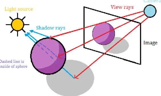
The fundamental ray tracing algorithm renders images by shooting rays into a 3D scene, computing the color of each pixel. The idea is to trace the path of light, but instead of tracing it from a light source it traces rays from the eye/camera back to the light source. Rays cast from the camera are called “primary rays” or “view rays”. When a primary ray hits an object, the algorithm further computes how much light is reflected from that hit point back to the camera. From the hit point it shoots a ray, called “shadow ray” to each
13 light source in the scene to see if there is any object blocking the way to a light source which makes the hit point in shadow. See figure 3 for a simple illustration of this.
Figure 3: A simple illustration of ray tracing with shadow rays.
If the surface of the hit point is reflective the algorithm becomes recursive, the direction of the reflection is computed and in that direction a ray is cast from the hit point to see if there is anything reflecting onto the hit point, these rays work similarly to the primary rays but are recursively cast from each hit point. The recursion stops when either the reflections contribution is too low or when a set maximum depth is reached. The amount of light reflected in that point and the surface properties are then used to compute the shading of that specific point.
When a surface is transparent, further rays are cast and computations are done, but this study won’t focus on having scenes which incorporates refraction and therefore that part of the algorithm is left out.
4.1.1 Illumination model
The surface properties of each object will include the material of the surface, which is defined by three vectors deciding the ambient, diffuse and specular reflection and a value called the Phongexponent represents the object’s shininess [42]. Each light source also has three vectors deciding the ambient, diffuse and specular intensity of that light.
The ambient lighting in a scene often refers to the intensity of non-directional light. This light decides the intensity of the color of an object in shadow, since the non-directional light is the only light hitting that object.
14 𝐿𝑎 - The resulting ambient color of the hit point.
𝐼𝑎 - The ambient light intensity in the scene.
𝑘𝑎 - The ambient reflection coefficient of the material.
One known model of diffuse reflection is the Lambert Illumination model (see figure 4). According to Lambert’s law the intensity of the illumination in a point where the surface is diffuse is proportional to the cosine of the angle between the surface normal vector and the vector in the direction to the light source (cos θ = NL).
Figure 4: The Lambert Illumination model. Illustration of how the different vectors L (towards the light source) and N (surface normal) relate to each other.
𝐿
𝑑= 𝐼 𝑘
𝑑(𝑁 ∙ 𝐿)
𝐿𝑑 - The resulting diffuse reflection of the hit point. I - The intensity of the point light source.
𝑘𝑑 - The diffuse reflection coefficient of the material.
N - The surface normal vector.
L - The vector in the direction to the light from the hit point.
Shiny surfaces have specular reflection (see figure 5) and by adding the specular contribution to the final color of the hit point, we get Phong’s model [42]. Which is a combination of ambient, diffuse and specular contribution, giving an object both shadows and highlights.
Figure 5: Shows the relation between the L (towards the light source), N (surface normal), the reversed V (view ray) and R (reflection) vectors. Alpha is the angle between the reversed view ray and reflection ray. The specular reflection is represented by the following equation: 𝒄𝒐𝒔𝒏𝜶 = (𝑹 ∙ 𝑽)𝒏
15
𝐿 = 𝐼
𝑎𝑘
𝑎+ 𝐼 𝑘
𝑎( 𝑁 ∙ 𝐿 ) + 𝐼 𝑘
𝑠(𝑹 ∙ 𝑽)
𝒏
The last part of the equation defines the specular reflection.
L - The resulting reflected light.
𝑘𝑠 - The specular reflection coefficient of the material.
R - The reflection vector.
V - The reversed viewing vector, with the direction from to surface instead of pointing to
the surface.
n - The exponent of the cosine function, referred to as the Phong exponent. The higher the
value the less scattered are the highlights on a surface (see an illustration of this in figure 6).
Figure 6: Illustration of how the light is scattered on a surface based on the phong exponent. From the leftmost to the right the value of the Phong exponent increases. The figure is taken from [43].
4.2 Acceleration structures
In this section three different well-known acceleration data structures will be presented: Uniform Grid, Kd-Tree and BVH, where versions of the latter is used by the Embree API. Accelerations structures are used to minimize the amount of checks done in order to find an intersection, i.e. a scene with multiple objects, a ray is fired and hits one object, the acceleration structure somehow needs to skip searching for an intersection point in remaining objects far away from the ray.
Both the Uniform grid and Kd-Tree use a subdivision technique, by dividing a volume of space into two or more sub-volumes and then if required, recursively repeat subdivision on the sub-volumes of the original volume which results in a tree-like structure of partitions where each leaf-volume holds a reference to all triangles inside it. The uniform grid only divides the original scene volume once which creates a grid of leaf-volumes, while the Kd-tree recursively subdivides the scene volume until some condition is met, which is based on both the scene geometry and subdivision scheme.
Uniform Grids are defined by a given bounding box of the scene to render and a list of triangles. When the grid is built, the resolution of the grid along the three axes can be set. With higher resolution there will be more voxels that are smaller in size, where each voxels consist of fewer triangles which results in fewer intersection tests per voxel but longer time when traversing the grid [44].
16 Kd-trees (the K represents the dimension of the tree) is a structure that represent the scene as a hierarchical structure based on a binary tree, where each internal node is a partition of the scene containing a splitting plane and two subtrees and each leaf nodes (corresponding voxels) consist of triangles [44].
Bounding volume hierarchies consist of a root, which is a bounding volume that contains all the bounding volumes in that scene. Each internal node have one or multiple internal nodes containing bounding volumes or leaf-nodes consisting of a number of triangles. Bounding volume hierarchies are hierarchical scene partitioning structures. The objects are partitioned opposed to space, which differs from the spatial subdivision techniques used to structure Kd-trees and uniform grids. A bounding volume is a simple geometric form that surrounds some geometry. The axis-aligned bounding box is one of the most used shapes, since it leads to fast construction and efficient intersection tests [22]. Another useful and classic choice is the bounding sphere, which also provides very fast intersection tests, and tight-fitting or even minimum bounding spheres can be computed very efficiently [38], [45]. Other possible choices are shapes that give a better fit in general, for example, oriented bounding boxes and ellipsoids, but they are not used as frequently as the simpler alternatives mentioned above.
5. Embree
Embree can be used as a library through the Embree API but it is also possible to adopt algorithms from Embree into your own code.
During runtime Embree chooses the traversal and build algorithms based on the instruction set architectures of the CPU it is running on. As seen in table 1, the kernels are supported by various Vector and SIMD instructions. The Embree API supports applications written in C++ but also applications written in ISPC, by providing an ISPC specific interface to the core ray tracing functionality.
17
Table 1: Embree System Overview (Taken from [46]).
Embree API (C++ and ISPC)
Ray Tracing Kernel Selection AccelerationStructure
Builders Subdivision Engine
Traversal Intersection Common Vector and SIMD Library
(Vec3f, Vec3fa, float4, float8, float16, SSE2, SSE4.1, AVX, AVX2, AVX512)
Embree contains algorithms for coherent workloads (e.g. primary and hard shadow rays) and incoherent workloads (e.g. Monte Carlo ray tracing algorithms, secondary rays) as well as support for single ray traversal, ray packets (4, 8, or 16) and hybrid packet/single ray traversal. Ray packets give faster ray traversal of coherent rays while hybrid is suggested for incoherent rays.
Two variants of intersection functions are available to use in the Embree API (header file “embree2/rtcore.h”), rtcIntersect which reports the first intersection and rtcOccluded which reports any intersection. When using packet rays (4, 8 or 16), packet versions of these functions exist.For performance reasons ray packets of 8 needs a CPU that supports AVX and when using ray packets of 16 the CPU must support the 16-wide Xeon Phi Instructions for 32-bit floats.
The ray layout to be passed to the ray tracing core is defined as ray structures in the Embree API header file “embree2/rtcore_ray.h”. It is also possible to use other ray structures that use alternative vector classes as long as the ray structures resemble the same binary data as the ray structures defined by Embree.
A ray is created using the following parameters: origin, direction and ray segment (tnear and tfar). Other input variables when creating a ray is time (which is used for motion blur) and mask (to mask out geometries) but these are optional to use and set to default values if nothing else is defined. The ray segment has to be in the range [0, ∞) since a ray can’t start before its origin but continue to infinity. Before tracing the ray, geometry-, primitive- and instance IDs are often set to “RTC_INVALID_GEOMETRY_ID” (-1). After tracing a ray and the ray hits a geometry, the hit distance will be set to the property for the end of ray segment (tfar). The ray structure also consist of an un-normalized geometry normal and barycentric u- and v-coordinates of the hit point, which are also set during this time. The geometry ID (geomID) will either have the ID of the geometry when using rtcIntersect or be set to 0 when using rtcOcclude. The geomID corresponds to the ID set during geometry creation, and the primitive ID (primID) corresponds to the
nth primitive of that geometry, e.g. nth triangle. When using instances the instance ID
18 geometry the IDs would still have the value set before tracing, which in most cases is “RTC_INVALID_GEOMETRY_ID”.
Embree API supports different types of geometry such as triangle meshes, instances, hair and user defined geometry. Geometries created inside a scene always belong to that scene and are accessed via a geometry identifier (geomID) of compact integer range. Triangle meshes were chosen to be used in the project, they are defined by vertex data (surface normal, texture coordinates etc.) and contain information about each face (e.g. which vertex indices compose it). A scene object is a container of one geometry or multiple geometries. When implementing a scene different flags are defined, e.g. scene type (static or dynamic), ray distribution model (coherent or incoherent) and the number of distributed rays (single ray or packet of 4, 8 or 16 rays). By committing a scene, the BVH build is triggered and based on the flags set, Embree interprets which kernels to choose in order to give the best performance [18][30]. Choosing a scene type decides how the BVH is built and traversed, unless any other flags for acceleration structures are set. Static scenes, use a high quality BVH build and fast trace, whereas dynamic scenes instead use a faster build but slower trace.
All acceleration structures in Embree are variants of BVHs. They have small memory footprints, aim for low build times and often offer fast traversal. Embree's BVHs are optimized for either memory consumption or performance, depending on the needs of the application [18]. Embree use two different builders: Object split which builds top-down with SAH binning and spatial split (morton code-based) which is 5 times slower than object split but may have around 2 times better render performance [35].
6. Implementation
The goal was to create a simple ray tracing application which included functionalities such as shading, shadows and texture mapping. It was also important to have the ability to load scenes from files. The project was implemented in the tutorial solution available from Embree’s website, (Embree version 6.2.2) [30]. In this solution there already existed a definition for the camera, functions for loading a scene from file and displaying pixels on the screen.
6.1 Initial preparation process
The scene file was loaded using the already existing function called loadOBJ and resulted in an instance of an ObjScene object being created. The file includes a reference to its material (.mtl) files and contains all the vertices, surface normals and texture coordinates for all the objects in a scene (including information about each face), while the material file contains all the values that defines properties of the material such as ambient, specular and diffuse intensity as well as opacity and textures.
19 When initializing the ray tracing core a call to the function rtcInit was made, sending a configuration string as input. The configuration string allows to configure implementation specific parameters such as the amount of threads to be used (default is to use all threads) and verbosity level (default is 0). The configuration string was set to NULL which resulted in the default configuration being used.
6.2 Programming the application
When creating a scene, different properties were set (see code example 1) called flags, these are interpreted by Embree to decide which kernels to use in order to give the best performance. But the flags are only hints and may be ignored by the implementation. The first goal of the implementation was to render a static scene without any dynamic geometries, this led to the choice of setting the scene type flag to static. Having a ray tracer with both primary rays and hard shadows (coherent rays), the acceleration structure flag was set to use coherent rays, which seemed to be the most suitable alternative. Setting the acceleration structure to be optimized for incoherent rays would be a good alternative for rendering applications based on Monte Carlo ray tracing and might be considered a good alternative when having a ray tracer with reflection enabled, rendering scenes with a lot of reflective surfaces (incoherent ray distribution). Two other alternatives to choose for the acceleration structure flag was “Compact” which creates a compact data structure and avoids algorithms that consume much memory and “High Quality” which builds higher quality spatial data structures (this is the default alternative for static scenes). “Robust” is another scene flag that can be used, it makes the traversal avoid any optimizations that reduce arithmetic accuracy. This was not used since traversal-speed was more prioritized than having arithmetic accuracy.
The second parameter of the rtcNewScene function (see code example 1) is algorithm flags, they specify which ray queries are required by the application. Intersect1 was chosen, to test the fundamental performance of Embree, it sets the application to intersect a single ray with the scene. When aiming for higher performance on coherent rays it is recommended to use packet rays (intersect4, intersect8 or intersect16) [47].
After creating the RTCScene object all the meshes were added to the scene, calling the function rtcNewTriangleMesh for each mesh. The function returns the geometry ID for that specific mesh. The vertex and index buffer were shared using the function rtcSetBuffer since sharing buffers can significantly reduce the memory required by the application (see code example 1).
20
Code example 1: The OBJScene (loaded from file) was first converted to an ISPCScene and then converted to an RTCScene in the function convertScene.
By implementing the code in the Embree tutorial solution the screen is split up into tiles (8 x 8 pixels per tile) which are then during render executed in parallel. Each thread calls the renderTile function which then (if nothing else is defined) computes the color of each pixel inside that tile. The complete renderPixel function is shown in code example 3 and 4 below.
A ray was created to intersect the scene. It is defined by an origin, direction and ray segment (tnear, tfar). The geomID and primID (triangle ID) is initially set to RTC_INVALID_GEOMETRY_ID (which is -1). To find the closest hit distance the Embree API function rtcIntersect was used. After a ray has been traced the geomID will change to the closest hit geometry and the primID will be set to the hit triangle ID, unless nothing is hit, then it’ll still be RTC_INVALID_GEOMETRY_ID and instead the color of the background image which is mapped to wrap around the scene is returned.
When the hit geometry has any normals stored or any texture coordinates for the hit triangle both the normal and texture coordinates are interpolated and the material for the triangle is collected. For example, to get the color from a texture the function getTextureTexel3f is used, it’s a function already defined in the Embree tutorial solution but here with minor changes (see code example 2).
RTCScene convertScene(ISPCScene* scene_in)
{
int scene_flags = RTC_SCENE_STATIC | RTC_SCENE_COHERENT;
int scene_aflags = RTC_INTERSECT1;
RTCScene scene = rtcNewScene((RTCSceneFlags)scene_flags,
(RTCAlgorithmFlags) scene_aflags);
/* add all meshes to the scene */
for (int i = 0; i < scene_in->numMeshes; i++) {
/* get ith mesh */
ISPCMesh* mesh = scene_in->meshes[i];
/* create a triangle mesh */
unsigned int geomID = rtcNewTriangleMesh(scene_out,RTC_GEOMETRY_STATIC,
mesh->numTriangles, mesh->numVertices);
/* share vertex buffer */
rtcSetBuffer(scene_out, geomID, RTC_VERTEX_BUFFER, mesh->positions, 0,
sizeof(Vec3fa));
rtcSetBuffer(scene_out, geomID, RTC_INDEX_BUFFER, mesh->triangles, 0,
sizeof(ISPCTriangle));
} }
/* commit changes to scene */
return scene_out;
21
Code example 2: Function for getting the color from a texture at a specific coordinate.
When hitting an object the function renderPixel is executed, it computes the color of a pixel. For each light source in a scene a shadow ray with the origin of the current hit point and direction to each light source is traced to find any hit by calling the function rtcOccluded. When the shadow ray doesn’t hit anything the diffuse reflection of the material is added to the pixel along with the specular reflection and color properties from the texture and material of that point. The function for shading a pixel was implemented according to the phong shading model. Overall, the implementation realizes a basic ray tracer that incorporates both primary and shadow rays, phong shading, multiple light sources and texture mapping.
Vec3f getTextureTexel3f(void *_texture, const float s, const float t)
{
Texture *texture = (Texture*)_texture;
if (texture && texture->format == RGBA8) {
float sn = s - floor(s);
float tn = t - floor(t);
int iu = (int)(sn * (float)(texture->width)); if (texture->width_mask) iu &= texture->width_mask; else iu = min(iu,texture->width-1);
int iv = (int)(tn * (float)(texture->height)); if (texture->height_mask)iv &= texture->height_mask; else iv = min(iv,texture->height-1);
unsigned char *t = (unsigned char*)texture->data +
(iv * texture->width + iu) * 4;
return Vec3f( (float)t[0] * 1.0f/255.0f,
(float)t[1] * 1.0f/255.0f, (float)t[2] * 1.0f/255.0f );
}
return Vec3f(0.0f);
}
/* commit changes to scene */
return scene_out;
22
7. Results
The implemented application shows the performance of a ray tracer using the basic settings of Embree. The tests focused on shadows and simple shading and was done by positioning the camera inside each scene to rotate around itself during one minute, viewing everything around it. At each frame performance data for both rendering and displaying pixels was gathered and written to a file, this data included frame rate, frame time and frame number. The FPS was an estimate based on the time it took to render a single frame and was computed using the following formula: FPS = 1 / t where t is frame time in seconds. The targeted FPS Ft was set to 120 FPS and was used to see how many
frames where dropped during render and was also set to a higher value than the acceptable framerate of 30 FPS to get a wider spread of frame numbers. The targeted frame time was the time in milliseconds that each frame should take to render and display in order to reach the targeted FPS, the targeted frame time was computed by the following formula: (1000 / Ft).
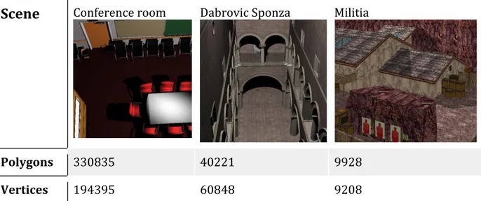
Three different scenes were chosen (See table 2 below), two indoors and one outdoors. The scene with the lowest amount of polygons, “Militia” is the only mesh copied from a real map in a game, namely the old game Counter Strike (1999) (Scene is taken from [48]). Not to mix up with newer versions of Counter Strike such as the game Counter Strike: Global Offensive. The second largest scene used is called “Dabrovic Sponza” which shows the interior of a palace and the third scene tested, which consists of the most polygons is “Conference room” and is simply a model based on a conference room (these scenes were taken from [49]).
23
Table 2: Polygon count and amount of vertices in each scene.
Scene
Conference room Dabrovic Sponza MilitiaPolygons 330835 40221 9928
Vertices 194395 60848 9208
All scenes were rendered at three different resolutions: 800 x 600, 1024 x 768 and full HD 1920 x 1080 using the implemented ray tracer running on Windows 7 64bit with 16GB RAM having an 8 core Intel CPU (Intel i7-5960X). The ray tracer was implemented in Microsoft Visual Studio 2013 and compiled using Microsoft Visual Studio Compiler. Today 3D games rarely play out in resolutions lower than full HD, but lower resolutions were chosen for the purpose of comparing and to put the project in perspective (comparing it to related work).
The following figure (Figure 7) shows the render FPS and display FPS during one minute in the scene “Conference room” at a resolution of 1024 x 768. There is a clear pattern of the FPS repeatedly dropping and raising, which is a result of the camera rotating in the scene.
Figure 7: This is two graphs showing the frame rate (see the vertical axis) during one minute of camera rotation in the scene “Conference room” at a resolution of 1024 x 768. The render FPS is based on the frame time it took to render the image, whilst the display is computed from the time it took to render plus the time it took to display the image, which naturally results in slightly lower FPS than render FPS alone.
7 8 9 10 11 12 13 14 15 16
Conference room 1024x768
Render FPS Display FPS24 Looking at figure 7, the “Render FPS” and “Display FPS” graphs almost overlap, with “Display FPS” display having slightly lower performance. Based on the fact that displaying an image is of most value in a game, the displayed frame rate was chosen to be the value to represent performance in all results below.
When looking at min, max and average frame rates in each scene (see figure 8) there’s a clear presentation of the performance getting lower when the resolution becomes larger.
Another interesting observation is the fact that the scene “Dabrovic Sponza” has an overall lower performance, even lower than the scene built of the most polygons, “Conference room”, but the difference is very small between the two. The scene with the least polygons, “Militia”, shows the overall best performance.
Figure 8: The min, max and average FPS in the scenes: “Conference room”, “Dabrovic Sponza” and “Militia”. Each scene rendered at the resolutions of 800 x 600, 1024 x 768 and 1920 x 1080 pixels.
The results show frame rates of a real time ray tracer with an average of around 30 FPS when rendering the scene “Militia” a lower resolution. The resolution suffers from the requirement of being low (e.g. 800 x 600) in order to reach playable frame rates and looking at the results from rendering at a resolution of full HD (1920 x 1080) no scene reached an average of 30 FPS (see Figure 8 above).
The following figures (Figure 9 - 11 below) shows the frame rates of the camera rotating in each scene at different resolutions. With higher resolution, each frame takes longer to render, which gives a result of lower frame rates and slows down the time it takes to rotate. According to the article [11] this can be prevented, by making the application frame independent, which some games actually do today.
0 5 10 15 20 25 30 35 40 45 50 55 60 80 0x 60 0 10 24 x7 68 19 20 x1 08 0 80 0x 60 0 10 24 x7 68 19 20 x1 08 0 80 0x 60 0 10 24 x7 68 19 20 x1 08 0
Conference room Dabrovic Sponza Militia
MIN, MAX and AVERAGE
MIN MAX AVERAGE
25
Figure 9: This diagram shows all the frame rates during one minute of the camera rotating inside the scene “Conference room” at the three different resolutions. At the highest peak rendering the scene at 800 x 600 a frame rate of around 25 FPS was reached.
Figure 10: These are the resulting frame rates of the rotating camera inside the scene “Dabrovic Sponza”, at three different resolutions. The highest peak rendering the scene at a resolution of 800 x 600 was around 20 FPS. 0 5 10 15 20 25 30
Conference room FPS
1920x1080 1024x768 800x600 0 2 4 6 8 10 12 14 16 18 20 22 24 26 28 30Dabrovic Sponza FPS
800x600 1024x768 1920x108026
Figure 11: This is the performance results in FPS from rendering the scene “Militia” at three different resolutions. This scene had the overall best performance, reaching the highest average frame rate in total. The results from the scene rendered at a resolution of 800 x 600 could be a good candidate for a stable frame rate of 30 FPS.
With the scenes being structured very differently, it's interesting to see that each scene still have similar patterns of highs’ and lows’ in the figures above (figure 9-11). An idea of testing this observation could be to render a scene with the exact same objects placed in a circle in which the camera is rotating around its center to see if similar patterns of the frame rate is achieved.
Of course, games require more than just simple lighting, static scenery and objects, a real game consists of animations and/or multiple players and not to mention special effects and lighting. Adding more objects inside any of the tested scenes would in general add to the render and display times, giving a result of even lower frames per second.
With regard to the timeframe of this project further features of the ray tracers weren’t added and/or tested, e.g. test scenes with reflective mirrors, refraction and add multiple animated objects inside scenes.
8. Alternative experimental setups
The current results show of Embree’s basic potential and can be used as a baseline to compare with improved experimental setups.
The developed ray tracer currently shoots both primary- and shadow rays, which are coherent rays. There is a need for other experiments to be made in which the implementation should make use of RTCRay8 instead of RTCRay, since the use of packet rays is important when aiming for higher performance on coherent rays [47]. This would require a few changes in the implementation; Intersect8 should be the selected alternative during scene creation when choosing the scene flags and the renderPixel
0 5 10 15 20 25 30 35 40 45 50 55 60
Militia FPS
1920x1080 1024x768 800x60027 function would need to call the Intersect8 function and make use of instructions to compute the color for all the eight pixels hit by the eight rays. Intersect16 was not considered since it, for performance reasons, needs a CPU that supports the 16-wide Xeon Phi Instructions for 32-bit floats which in this case the CPU didn’t.
Another alternative to have in mind is incorporating reflection and refraction rays, which typically are incoherent. This would mean that the previous mentioned alternative would need to add some functionality. Since using only single or packet rays would perform less well rendering incoherent rays. Instead in scenes with a mix of coherent and incoherent ray distributions, both the intersection and traversal performance can benefit from using a hybrid ray distribution by dynamically switching between the use of packet and single rays [18].
9. Discussion
Based on the results, acceptable frame rates was achieved (30 FPS) when rendering the scene “Militia” at the lowest resolution (800 x 600), having simple shading and casting both primary and shadow rays. Since most games today run at a resolution of Full HD (1920 x 1080) and require at least an acceptable framerate of 30 FPS at that resolution, the ray tracer developed here would not be a valid option for rendering games today at its current state.
Looking at the different resulting figures (9-11) the frame ratesrepeatedly drop and raise. The reason for this could probably be because of the amount of polygons visible at a different angle during the rotation, e.g. when facing a wall the FPS could be high and get lower when more objects become visible.
Looking at the scenes “Conference room” and “Dabrovic Sponza” (see figure 8), the “Dabrovic Sponza” scene has an overall lower performance than the scene “Conference room” (which is built of the double amount of polygons). The reason for lower performance evidently isn’t only based on the polygon count, one speculation is that the frame time of rendering “Dabrovic Sponza” is slower because of all the textures used when rendering in comparison to “Conference room” which doesn’t use any textures at all. Another possible reason could be the quality of the BVH used when rendering the scene “Dabrovic Sponza”, since having many small and large polygons grouped together could make large bounding volumes around small triangles, which is a problem. Performance depends on which builder (object split or spatial split) was used to create the BVH. The scenes tested didn’t have any animated objects in them (only few static objects), it was only the camera that was animated. If several animated objects were to be added inside the scenes the frame rates would at some point drop, resulting in even lower performance. A lower frame rate or many drops in the frame rate would make the game look “choppy” [11], [12]. In order to get a better performance when using animated
28 objects the scene definition during implementation needs to be changed, e.g. flag RTC_SCENE_DYNAMIC instead of RTC_SCENE_STATIC, but as mentioned, these flags are only hints and may be ignored by the implementation.
Embree is designed to give high performance, specifically when rendering scenes in which complex geometry and incoherent ray distributions are common, namely using ray tracing techniques such as Monte Carlo Ray tracing [18]. But what differences in performance can be expected when using Embree in a Whitted-styled ray tracer, as in this project? Related research show that Embree has potential for higher performance. In the paper [18] they implement two different path tracers that makes use of Embree’s kernels, one written for ISPC which is a compiler developed at Intel to compile a c - based SPMD programming language. The results of a comparison between the two shows that Embree has potential of much higher performance, when using ISPC [18], [30]. It is also stated on the Embree Webpage that using Intel’s own Compiler (Intel Compiler 15.0.2) would improve the performance by approximately 10% [30].
In [9] high performance were presented (30 - 43 FPS in scenes of an average polygon count which is higher than the average of the scenes used in this project, 66 - 871 thousand polygons in comparison to 9 - 331 thousand polygons) using commodity hardware to render at a resolution of 1024 x 1024, but the results are based on rendering using primary rays only together with simple shading. Similarly, Ludvigsen and Elster discuss the performance of Aila and Laine’s work [16], by only measuring frame rates based on primary rays, giving roughly 95 - 180 FPS in scenes ranging from 54 - 282 thousand polygons [4]. By only shooting primary rays with simple shading, even at higher resolutions, higher performance can be reached. But the visible result is important, especially in a game and without shadow rays (or other secondary rays) the beneficial aspects of ray tracing that a game would need are lost.
10. Conclusions
A simple ray tracer was implemented using the Embree API (with basic settings, RTCRay). Based on the results when testing the performance of the ray tracer, rendering at lower resolutions (e.g. 800 x 600), casting both primary- and shadow rays, together with some simple shading, an average frame rate of around 30 FPS was achieved in the scene “Militia. The other scenes did not reach 30 FPS regardless of the resolution. Related research show that Embree has potential for higher performance when making use of ISPC (as seen in [18]) and by using Intel’s own compiler (Intel Compiler 15.0.2 was used by the Embree developers) could give a slight increase of performance [30], [18].
So, is it possible for hardware accelerated ray tracing libraries to achieve acceptable frame rates on simple 3D game environments? The resulting ray tracer in this project shows that an acceptable frame rate can’t be reached using relatively simple scenes even with a
29 high-end CPU, considering the standard today having a resolution of Full HD (1920 x 1080). Especially not in a next-gen game where high detail and complexity is a must. However, ray tracing has great potential, looking back, the performance has improved. Real-time frame rates are possible to reach using the available hardware and systems out today, but is still very limited to low resolutions and simple shading.
10.1 Future work
The implemented ray tracer could be updated with more features that matches the needs of computer games today, making it even more valuable to test i.e. by adding animated objects in the scenes and incorporate other functionalities of a ray tracer such as reflection, refraction and using soft shadows. To gain higher performance it would be a good option to implement the application in ISPC and make use of hybrid rays (switching between single- and packet rays) in order to get better performance in scenes with both coherent and incoherent rays.
30
References
[1] P. Christensen, J. Fong, D. Laur and D. Batali, “Ray Tracing for the Movie ‘Cars’”, IEEE
Symposium on Interactive Ray Tracing, pp. 1 - 6 , September 2006.
[2] C. Chan, D. Psaltis and F. Özel, “GRay: a massively GPU-based code for ray tracing in relativistic spacetimes”, The Astrophysical Journal, vol. 777, no. 13, November 2013. [3] T. Yapo and B. Cutler, “Rendering lunar eclipses”, Proceedings of Graphics Interface
2009, pp. 63-69, 2009.
[4] H. Ludvigsen and A. C. Elster, “Real-Time Ray Tracing Using Nvidia OptiX”,
Eurographics Short Papers, pp. 65-68, 2010.
[5] C. Benthin and I. Wald, “Efficient ray traced soft shadows using multi-frusta tracing”,
Proceedings of the Conference on High Performance Graphics 2009, New York: ACM, pp.
135-144, 2009.
[6] H. Friedrich, J. Günther, A. Dietrich, M. Scherbaum, H. Seidel and P. Slusallek, “Exploring the use of ray tracing for future games”, Proceedings of the 2006 ACM
SIGGRAPH symposium on Videogames, New York: ACM , pp. 41-50, 2006.
[7] K. Claypool and M. Claypool, “On frame rate and player performance in first person shooter games”, Multimedia Systems, vol. 13, pp. 3-17, 2007.
[8] I. Wald et al., “State of the Art in Ray Tracing Animated Scenes”, In STAR Proceedings
of Eurograpics 2007, 2007.
[9] M. Shih, Y. Chiu, Y. Chen, C. Chang, “Real-Time Ray tracing with CUDA”, Algorithms
and Architectures for Parallel Processing, pp. 327-337, 2009.
[10] D. Pohl, “Quake wars gets ray traced”, Intel Visual Adrenaline, no. 2, pp. 34-38, 2009. [Online] Available:
http://www.wolfrt.de/pdf/Light%20It%20Up!%20Quake%20Wars%20Gets%20Ray% 20Traced.pdf =EN. [Retrieved: 28 October, 2015]
[11] W. Copeland, “Understand the importance of frame rate”, IGN, November 2014. [Online] Available:
http://www.ign.com/articles/2014/11/05/understanding-frame-rate-and-its-importance =EN. [Retrieved: 28 October, 2015]
[12] S. Sarkar, “Why frame rate and resolution matter: A graphics primer”, Polygon, June 2014. [Online] Available:
31 http://www.polygon.com/2014/6/5/5761780/frame-rate-resolution-graphics-primer-ps4-xbox-one =EN. [Retrieved: 28 October, 2015]
[13] J. Schmittler, D. Pohl, T. Dahmen, C. Vogelsang and P. Slusallek, “Realtime Ray
tracing for current and future games”, ACM SIGGRAPH 2005 Courses, New York: ACM, No. 23, 2005.
[14] Intel Corporation [Online] Available: http://www.intel.com/ =EN. [Retrieved: 28 October, 2015]
[15] “What is CUDA?”, Nvidia. [Online] Available:
http://www.nvidia.com/object/cuda_home_new.html =EN. [Retrieved: 28 October, 2015]
[16] T. Aila and S. Laine, “Understanding the efficiency of ray traversal on GPUs”,
Proceedings of the Conference on high Performance Graphics 2009, New York: ACM, pp
145-149, 2009.
[17] J. Nah, J. Kim, J. Park and W. Lee, “HART: A Hybrid Architecture for Ray Tracing Animated Scenes”, IEEE Transactions on Visualization and Computer Graphics, vol. 21, no. 3, 2015.
[18] I. Wald I, S. Woop, C. Benthin, G. Johnson and M. Ernst. “Embree: a kernel framework for efficient CPU ray tracing”, ACM Transactions on Graphics (TOG) -
Proceedings of ACM SIGGRAPH 2014, Article no. 143, vol. 33, no. 4, July 2014.
[19] M. Zlatuška and V. Havran, “Ray Tracing on a GPU with CUDA - Comparative Study of Three Algorithm”, Faculty of Electrical Engineering, Czech Technical University in Prauge, 2010.
[20] G. Müller and D. Fellner, “Hybrid Scene Structuring with Application to Ray Tracing”, Tech. rep. Institute of Computer Graphics, TU Braunchweig, Germany, 1999. [21] T. Larsson and T. Akenine-Möller, “A Dynamic Bounding Volume Hierarchy for Generalized Collision Detection”, Computers & Graphics, Elsevier Ltd, vol. 30, no. 3, pp. 450-459, June, 2006.
[22] I. Wald, S. Boulos and S. Peter, “Ray Tracing Deformable Scenes Using Dynamic Bounding Volume Hierarchies”, ACM Transactions on Graphics, vol. 26, no. 1, 2007. [23] I. Wald, “On fast Construction of SAH-based Bounding Volume Hierarchies”,
32 [24] T. Purcell, I. Buck, W. Mark and P. Hanrahan, “Ray tracing on programmable
graphics hardware”, SIGGRAPH ’02: Proceedings of the 29th annual conference on
Computer graphics and interactive techniques , pp. 703–71, July 2002.
[25] N. Carr, J. Hoberock, K. Crane and J. Hart, “Fast GPU ray tracing of dynamic meshes using geometry images”, GI’06 Proceedings of Graphics Interface, pp. 203-209, 2006. [26] T. Foley and J. Sugerman, “KD-tree acceleration structures for a GPU ray tracer”,
HWWS ‘05 Proceedings of the ACM SIGGRAPH/EUROGRAPHICS conference on Graphics Hardware, New York: ACM, pp. 15-22, 2005.
[27] “GPGPU (General Purpose Graphical Processing Unit)”, SCAI, 2012. [Online]
Available: http://www.hpc.cineca.it/content/gpgpu-general-purpose-graphics-processing-unit =EN. [Retrieved: 28 October, 2015]
[28] “What is GPU accelerated computing?”, Nvidia. [Online] Available: http://www.nvidia.com/object/what-is-gpu-computing.html =EN. [Retrieved: 28 October, 2015]
[29] “NVIDIA® OptiX™ Ray Tracing Engine”, Nvidia. [Online] Available: https://developer.nvidia.com/optix =EN. [Retrieved: 28 October, 2015]
[30] Embree [Online] Available: https://embree.github.io/ =EN. [Retrieved: 28 October, 2015]
[31] A. Dietrich, I. Wald, C. Benthin and P. Slusallek, “The OpenRT Application Programming Interface - Towards A Common API for Interactive Ray Tracing”,
Proceedings of the 2003 OpenSG Symposium, p. 23-31, 2003.
[32] D. Kozlov, “FireRays SDK – High Efficiency, High performance”, AMD. [Online] Available: http://developer.amd.com/tools-and-sdks/graphics-development/firepro-sdk/firerays-sdk/ =EN. [Retrieved: 6 December, 2015]
[33] S. Parker et al., “OptiX: A General Purpose Ray Tracing Engine”, ACM SIGGRAPH
papers, New York: ACM, Article no. 66, July 2010.
[34] I. Georgiev, D. Rubinstein, H. Hoffmann and P. Slusallek, “Real Time Ray Tracing on Many-Core-Hardware”, Tech. rep. German Research Center for Artificial Intelligence &
Computer Graphics Group, Saarland University, Germany, 2008.
[35] M. Ernst, “Embree: Photo-Realistic Ray Tracing Kernels”, Intel Corporation, August 2011. [Online] Available:
33 https://software.intel.com/sites/default/files/m/d/4/1/d/8/Embree_Final.pdf =EN. [Retrieved: 28 October, 2015]
[36] H. Kniberg & M. Skarin, Kanban and Scrum: making the most of both, USA: C4Media, 2010.
[37] “The Stanford 3D Scanning Repository”, Stanford, 2014. [Online] Available: http://graphics.stanford.edu/data/3Dscanrep/ =EN. [Retrieved: 28 October, 2015] [38] T. Whitted, “An improved illumination model for shaded display”, Communications
of the ACM, vol. 23, no. 6, pp. 343-349, 1980.
[39] C. Birger, L. Correia & A. Hedblom, “Monte Carlo Ray Tracing and Photon Mapping”, Tech. rep., Linköping University, January 2010.
[40] T. Purcell, C. Donner, M. Cammarano, H. Jensen & P. Hanrahan, “Photon mapping on programmable graphics hardware”, SIGGRAPH ‘05 ACM SIGGRAPH 2005, New York: ACM, Article no. 258, July 2005.
[41] W. Jarosz, H. Jensen & C. Donner, “Advanced global illumination using photon mapping”, ACM SIGGRAPH 2008 classes, New York: ACM, Article no. 2, p. 1-112, 2008. [42] B. Phong, “Illumination for Computer Generated Pictures”, Communications of the
ACM, New York: ACM, vol. 18, no. 6, pp. 311-317, June 1975.
[43] “Illumination Models”, Bournemouth Academy. [Online] Available:
http://nccastaff.bournemouth.ac.uk/jmacey/CGF/slides/IlluminationModels4up.pdf =EN. [Retrieved: 28 October, 2015]
[44] N. Thrane, L. Simonsen, “A Comparison of Acceleration Structures for GPU Assisted Ray Tracing”, Denmark, Master Thesis, August 2005.
[45] T. Larsson, “Exact Bounding Spheres by Iterative Octant Scan”, In Proceedings of
SIGRAD 2015, p. 9-12, June 2015.
[46] Intel, “Embree ray tracing kernels”, Slideshare. [Online] Available:
http://www.slideshare.net/IntelSoftware/embree-ray-tracing-kernels =EN. [Retrieved: 9 December, 2015]
[47] M. Ernst & S. Woop, “Embree: Photo-Realistic Ray Tracing Kernels”, Intel Corporation, June 2011.
34 http://tf3dm.com/3d-model/cs-militia-50183.html =EN. [Retrieved: 28 October, 2015] [49] M. McGuire, “Meshes”, McGuire Graphics Data, 2012. [Online] Available:
![Figure 1: Four different screenshot of the game Quake 3 rendered using a ray tracing engine (figure taken from [13]).](https://thumb-eu.123doks.com/thumbv2/5dokorg/4874459.133113/7.892.107.792.370.496/figure-different-screenshot-quake-rendered-tracing-engine-figure.webp)
![Table 1: Embree System Overview (Taken from [46]).](https://thumb-eu.123doks.com/thumbv2/5dokorg/4874459.133113/17.892.111.786.138.296/table-embree-overview-taken.webp)