1 (104)
Achieving New Standards in
Prosthetic Socket
Manufacturing
Master thesis
Advanced level, 30 hp
Mälardalen University
Department of Innovation, Design, and Engineering Product and Process Development
Arman Tommy Gharechaie
Omid Darab
Report Number:
Supervisor, Company: Hualiang (Neo) Ni, OYMotion Technologies Supervisor, University: David Bizzozero, Mälardalens högskola Examiner: Sten Grahn, Mälardalens högskola
2 (104)
ACKNOWLEDGEMENTS
We want to thank the following people who have aided us in conducting this research. Special thanks to Hualiang (Neo) Ni for receiving us and for his continuous support.
David Bizzozero for supervising this research from our university in Sweden and for counsel and constructive feedback.
Axel Öberg for allowing use of the university’s 3D-printer and providing instructions. Henrik Lekryd for sharing knowledges on 3D-printing and rapid prototyping at Mälardalens university.
Janne Carlsson for sharing knowledges on lightweight design.
Fredrik Finnberg from Digital Mechanics for sharing knowledges on additive manufacturing techniques and material selection.
Yuelin Yang and Chaofeng Wang for participating in our interviews.
//Omid Darab & Arman Gharechaie. May 25th, 2018.
3 (104)
ABBREVIATIONS
3D Three-DimensionalABS Acrylonitrile Butadiene Styrene AI Artificial Intelligence
AM Additive Manufacturing ASTM American Society for Testing
CAD Computer Aided Design CNY Chinese Renminbi Yuan
DFA Design For Assembly DFC Design For Cost
DFM Design For Manufacturing DFR Design For Reliability DFV Design For Value
DMADV Define Measure Analyze Design
Validate
DMLS Direct Metal Laser Sintering EBM Electron Beam Melting
ECAD Electrical Computer Aided Design EMG Electromyography
EVA Ethylene-Vinyl-Acetate FDM Fused Deposition Modeling
FMEA Failure Modes and Effects
Analysis
LOM Laminated Object Manufacturing MCAD Mechanical Computer Aided
Design
MJF Multi-Jet Fusion
MoSCoW Must Should Would Could PA Polyamide
PBF Powder Bed Fusion PC Polycarbonate PE Polyethylene PEEK Polyetheretherketone
PLA Polylactic
RAM Random Access Memory SEK Swedish Crowns
SLM Selective Laser Melting SLS Selective Laser Sintering STL Stereolithography (file format) TM&C Temperature Measurement and
Control System
TMR Targeted Muscle Reinnervation UTC Coordinated Universal Time
4 (104)
ABSTRACT
Preface: The research about product development of a prosthetic socket was conducted by
two students from Mälardalen University, department of Innovation, Design, and Technology.
Background: The most recent public survey shows that an estimated 5 million people in
China are amputees, out of which a significantly large portion are below-elbow amputees. Sockets sold to below-elbow amputees are equipped with only two surface electromyography sensors, has low comfortability, has problems with perspiration, and a high weight. The current standard for socket manufacturing has not changed in decades.
Research Questions: The following research questions have determined the direction of the
research: (1) What measurable factors contribute to a convenient and ergonomic feature design in prosthetic socket from the end-user’s perspective? (2) How can the weight and functionality be improved to achieve a prosthetic socket more suited to the end-user, with respect to the existing prosthetic socket? (3) Which material and manufacturing method is suitable for producing cost-effective and customized prosthetic sockets?
Research Method: The research was guided by the 5th edition of Product Design and
Development by Ulrich & Eppinger (2012) where the product development process described in five of the six phases from planning to test and refinement were utilized.
The data collection and analysis techniques performed in this research was guided by
Research Methods for Students, Academics and Professionals by Williamson & Bow (2002). Interviews were conducted with five different stakeholders to find specifications of
requirements and concretize subjectivism of what defines quality and ergonomics.
Implementation: Currently, below-elbow amputees order sockets from orthopedic clinics.
The socket was identified as a product of Ottobock. Investigations were made to find optimal solutions to the specification of requirements.
Results: The development of a socket concept was designed for additive manufacturing using
a multi-jet fusion printer.
Analysis: This concept had significant improvements to parameters: higher grade of
customizability, 30 % reduced weight, 48 % cost reduction, a new production workflow with 93,5 % automation, and a 69 % reduction in manual work hours.
Conclusions: The data of the research strongly indicate existing potentials in enhancing
socket design techniques and outputs by implementation of additive manufacturing processes. This can prove to be beneficial for achieving more competitive prosthetics and associated services.
5 (104)
SAMMANFATTNING
Förord: Denna forskning om produktutvecklingsprocessen av en armprotes genomfördes av
två studenter från Mälardalens universitet, avdelningen för innovation, design och teknik.
Bakgrund: Den senaste offentliga undersökningen visar att cirka 5 miljoner människor i Kina
är amputerade, varav en betydligt stor del är under-armbågsamputerade.
Armproteser som säljs till underarmsamputerade individer är utrustade med endast två yt-elektromyografiska sensorer, har låg komfort, har problem med perspiration och hög vikt. Den nuvarande standarden för armproteser har inte förändrats under årtionden.
Forskningsfrågor: Följande forskningsfrågor har bestämt riktningen för forskningen: (1)
Vilka mätbara faktorer bidrar till en praktisk och ergonomisk funktionsdesign i
underarmsproteser ur slutanvändarens perspektiv? (2) Hur kan vikten och funktionaliteten förbättras för att åstadkomma en underarmsprotes som är bättre anpassad för slutanvändaren med avseende på den befintliga underarmsprotesen? (3) Vilket material och
tillverkningsmetod är lämpligt för att producera kostnadseffektiva och anpassade underarmsproteser?
Forskningsmetod: Forskningsmetoden styrdes av den femte upplagan av Product Design
and Development av Ulrich & Eppinger (2012) där produktutvecklingsprocessen är uppdelad i sex faser. I denna forskning användes de fem första faserna från planering till testning och justering.
Tekniker för datainsamling och analys som användes i denna forskning styrdes av Research Methods for Students, Academics and Professionals av Williamson & Bow (2002).
Intervjuer genomfördes med fem olika intressenter för att hitta kravspecifikationer och för att konkretisera subjektivitet för vad som definierar kvalitet och ergonomi.
Implementering: Underarmsamputerade individer beställer för närvarande armproteser från
ortopediska kliniker. Armprotesen identifierades som en produkt av Ottobock. Undersökningar gjordes för att hitta optimala lösningar för kravspecifikationen.
Resultat: Konceptutvecklingen av en armprotes utformades för additiv tillverkning med hjälp
av en multi-jet-fusion-skrivare.
Analys: Det här konceptet hade betydande förbättringar av parametrar: högre grad av
anpassningsbarhet, 30 % minskad vikt, 48 % kostnadsreduktion, ett nytt produktionsflöde med 93,5 % automatisering och en 69 % minskning av manuella arbetstider.
Slutsatser: Data från denna forskning indikerar att det finns starkt potential för att förbättra
designtekniker och utgångar av underarmsproteser genom implementering av additiva tillverkningsprocesser. Detta kan visa sig vara fördelaktigt för att uppnå mer
6 (104)
TABLE OF CONTENTS
1 INTRODUCTION ... 10
1.1 BACKGROUND ... 10
1.2 OYMOTION TECHNOLOGIES INC ... 10
1.3 PROBLEM FORMULATION ... 11
1.4 GOALS AND PURPOSE ... 11
1.5 RESEARCH QUESTIONS ... 12
1.6 PROJECT DELIMITATIONS ... 12
2 RESEARCH METHOD ... 13
2.1 THEORETICAL DATA COLLECTION ... 13
2.2 EMPIRICAL DATA COLLECTION ... 13
2.3 PRODUCT DEVELOPMENT METHODS ... 14
2.4 PRODUCT DESIGN AND DEVELOPMENT PHASES ... 15
2.5 GANTT CHART ... 16
2.6 BRAINSTORMING... 16
2.7 COMPUTER AIDED DESIGN ... 16
2.8 SPECIFICATION OF REQUIREMENTS ... 16
2.9 FUNCTIONAL ANALYSIS ... 17
2.10 MOSCOW ... 17
2.11 SIX SIGMA (DMADV)... 17
2.12 5WHY’S (SIXSIGMA) ... 17
2.13 DESIGN FOR MANUFACTURING (DFM) ... 17
2.14 DESIGN FOR ASSEMBLY (DFA) ... 18
2.15 DESIGN FOR COST (DFC)... 18
3 THEORETICAL FRAMEWORK ... 19
3.1 MYOELECTRIC CONTROL OF PROSTHESES ... 19
3.2 ADDITIVE MANUFACTURING (AM) ... 19
3.3 THREE-DIMENSIONAL (3D)SCANNING ... 20
3.4 POWDER BED FUSION (PBF) ... 20
3.5 MATERIAL SELECTION DATABASE ... 23
4 IMPLEMENTATION ... 24
4.1 PROJECT PLANNING AND TIME SCHEDULE ... 24
4.2 MARKET ANALYSIS ... 24
4.3 DESIGN REQUIREMENTS AND CHALLENGES ... 25
4.4 FUNCTIONAL ANALYSIS AND SYSTEMS ... 27
4.5 WEIGHING OF SOCKET COMPONENTS ... 29
4.6 REQUIREMENTS SPECIFICATION ... 29
4.7 THE METHOD OF REVERSE-ENGINEERING A RESIDUAL LIMB ... 29
4.8 CURRENT STATE OF SOCKET MANUFACTURING ... 29
4.8.1 Current Price Model ... 30
4.8.2 Orthopedic Casting Process ... 30
4.8.1 Fabrication of EVA Plaster Mold ... 32
4.8.2 Lamination Process ... 33
4.8.3 Installment Process ... 33
4.9 ADDITIVE MANUFACTURING PROCESS ... 34
4.9.1 The Additive Manufacturing Method ... 38
4.10 EMGSENSOR ARRANGEMENT ... 40
4.11 MATERIAL SELECTION ... 43
4.11.1 Current design ... 44
7 (104)
4.12 SHAPE FACTOR (Φ) ... 49
4.13 CONCEPT GENERATION ... 53
4.13.1 Residual Limb Compartment Concepts ... 53
4.13.2 EMG Sensor Housing Concepts ... 53
4.13.3 Customizable Features Concepts ... 54
4.13.4 Socket Concepts ... 54
4.13.5 Cooling & Ventilation System Concepts ... 54
4.14 ACTIVE THERMAL REGULATION SYSTEMS ... 55
4.15 PASSIVE THERMAL REGULATION SYSTEMS ... 57
4.16 CONCEPT EVALUATION ... 60
4.17 CALCULATIONS ... 61
4.17.1 Manufacturing Process Workflow ... 61
4.17.2 Weight Optimization ... 62
4.17.3 Price estimations ... 63
5 RESULTS ... 64
6 ANALYSIS ... 67
6.1 DEGREE OF INDIVIDUALIZATION ... 67
6.2 VALUES OF THE 3D-SCANNING PROCESS ... 67
6.3 PROCESS WORKFLOW EFFICIENCY ... 68
6.4 DESIGN,MANUFACTURING, AND COST FACTORS ... 69
6.5 THERMAL REGULATION AND AIRFLOW ... 69
7 CONCLUSIONS ... 71
7.1 RESEARCH CONCLUSIONS ... 71
7.2 FURTHER RECOMMENDATIONS ... 71
7.3 FINAL WORDS ... 72
8 REFERENCES ... 73
APPENDIX I: USER INTERVIEWS ... 77
I:QUESTIONS FROM INTERVIEW FORMS (ENGLISH) ... 77
II:QUESTIONS FROM INTERVIEW FORMS (CHINESE,TRANSLATED) ... 79
III:INTERVIEW WITH MR.YANG ... 80
IV:INTERVIEW WITH MR.WANG ... 83
APPENDIX II: MATERIAL DATASHEETS ... 84
APPENDIX III: GANNT-CHARTS ... 91
APPENDIX IV: 5 WHY’S AND BRAINSTORMING ... 92
8 (104)
LIST OF FIGURES
FIGURE 1:THE PHASES OF THE PRODUCT DESIGN AND DEVELOPMENT PROCESS IN A SEQUENCE. ... 15
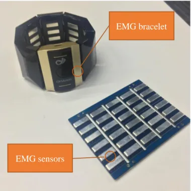
FIGURE 2:OYMOTION’S EMG SENSOR CIRCUITS COMPRISED OF THREE DRY ELECTRODES EACH, AND AN EMG BRACELET USED FOR TESTING. ... 19
FIGURE 3:THE PROCESS SCHEMATIC OF A CONVENTIONAL FDM PRINTER.(ALFRED,2014) ... 20
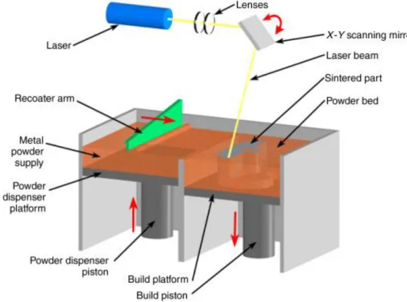
FIGURE 4:THE PROCESS SCHEMATIC OF A CONVENTIONAL SLS,DMLS, OR SLM PRINTER.(MORITZ & MALEKSAEEDI,2018) ... 21
FIGURE 5:SIDE-BY-SIDE COMPARISON OF SCHEMATICS FOR (A)EBM AND (B)SLM SYSTEMS. ... 22
FIGURE 6:CROSS-SECTIONAL VIEWS OF THE HPMULTI JET FUSION PRINTING PROCESS SCHEMATIC.(HP DEVELOPMENT COMPANY,L.P,2017) ... 22
FIGURE 7:A FLOWCHART ILLUSTRATION OF THE FUNCTIONAL SYSTEM... 27
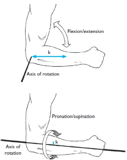
FIGURE 8:THE AXES OF ROTATION DURING FLEXION/EXTENSION AND PRONATION/SUPINATION.(HALL,2015) .... 28
FIGURE 9:THE TECHNICIAN, REMOVING PARTS AROUND THE ELBOW JOINT. ... 31
FIGURE 10:THE SOCKET AFTER THE TECHNICIAN HAD BORED EIGHT CONCENTRIC HOLES BASED ON MARKS WHERE THE SENSORS ARE GOING TO BE PLACED. ... 32
FIGURE 11:A CANISTER OF ORTHOPOX EPOXY RESIN FROM OTTOBOCK. ... 33
FIGURE 12:COMPARISON OF MIRRORING PROCESSES OF 3D-SCANNING AND ORTHOPEDIC CASTING. ... 34
FIGURE 13:THE WORKFLOW PROCEDURE OF ARTEC SPIDER SPACE 3D-SCANNER. ... 35
FIGURE 14:A TEST PRINT OF THE SCAN PERFORMED BY ARTEC SPACE SPIDER. ... 36
FIGURE 15:THE ARTEC-SPIDER SPAN INTERFACE. ... 37
FIGURE 16:SCANNING PROGRESS AND MAXIMAL READ ERRORS ARE SHOWN IN THE WORKSPACE. ... 37
FIGURE 17:ANYLON PA12 GEAR MADE USING THE MJF TECHNIQUE. ... 38
FIGURE 18:PROCESS WORKFLOW OF THE AM MANUFACTURING PROCESS. ... 39
FIGURE 19:POST-TMR AMPUTEE WITH UPPER-LEVEL AMPUTATION. ... 41
FIGURE 20:THE MATERIAL SELECTION PROCESS. ... 43
FIGURE 21:THE CHINESE MANUFACTURED DESIGN FROM OTTOBOCK. ... 44
FIGURE 22:A PICTURE SHOWING THE OTTOBOCK SOCKET’S PLACEMENT OF THE SENSORS. ... 45
FIGURE 23:YOUNG’S MODULUS AND YIELD STRENGTHS OF DIFFERENT MATERIALS.(CESEDUPACK 2019) ... 46
FIGURE 24:ANATOMY OF THE ELBOW JOINT.(GETBODYSMART ,2019) ... 46
FIGURE 25:ONE OF SEVERAL MATERIAL SCREENING CONCEPTS.(CESEDUPACK 2019) ... 48
FIGURE 26:DIFFERENT LOADS SCENARIOS.(HART, ET AL.,2017) ... 49
FIGURE 27:THE SOCKET IS SUBJECTED TO BENDING.THE GOAL IS TO FIND THE LIGHTEST SOCKET THAT IS NOT PLASTICALLY DEFORMED DURING SPECIFIC LOADS.THE MATERIAL SHOULD BE LIGHT AND STRONG BEAM. 49 FIGURE 28:SHAPE FACTOR AND MASS PER UNIT OF STRENGTH FOR DIFFERENT MATERIAL GROUPS.(CESEDUPACK 2019) ... 50
FIGURE 29:SHAPE FACTORS OF DIFFERENT POLYMERS.(CESEDUPACK 2019) ... 51
FIGURE 30:FUNCTIONAL SYSTEM OF THE SOCKET HOUSING CONCEPT... 53
FIGURE 31:FUNCTIONAL SYSTEM FOR THERMAL REGULATION. ... 57
FIGURE 32:HEAT DISTRIBUTION OF THE AUTHOR’S ARM, TAKEN WITH A THERMAL CAMERA. ... 59
FIGURE 33:A PASSIVE VENTILATION SYSTEM CONCEPT. ... 60
FIGURE 34:THE RESIDUAL LIMB COMPARTMENT ILLUSTRATED AS A SOLID BODY AND WITH HONEYCOMB PATTERN CREATED IN MESHMIXER.(FROM RIGHT TO LEFT) ... 64
FIGURE 35:ILLUSTRATION OF SENSOR PLACEMENT. ... 65
FIGURE 36:A3D-SCAN OF A RESIDUAL LIMB INSERTED INTO THE RESIDUAL LIMB COMPARTMENT AND THE SOCKET ADAPTER LYING TO THE LEFT OF IT. ... 65
FIGURE 37:CLOSE-UP OF THE SOCKET ADAPTER ILLUSTRATED AS A SOLID BODY. ... 66
FIGURE 38:SENSOR PROTRUDES INWARD TO THE SOCKET’S INTERIOR. ... 66
FIGURE 39:MATERIAL DATASHEET FOR ETHYLENE-VINYL-ACETATE (EVA) ELASTOMERS.(CESEDUPACK,2019) ... 84
FIGURE 40: CONTINUATION OF:MATERIAL DATASHEET FOR ETHYLENE-VINYL-ACETATE (EVA) ELASTOMERS. (CESEDUPACK,2019)... 85
FIGURE 41:ORTHOPOX EPOXY-RESIN MATERIAL FROM OTTOBOCK.(OTTOBOCK,2019) ... 86
FIGURE 42:MATERIAL DATASHEET FOR POLYAMIDES (PA).(CESEDUPACK,2019) ... 87
9 (104)
FIGURE 44:TECHNICAL DATASHEET OF HP3DHIGH REUSABILITY PA12.(HPDEVELOPMENT COMPANY,L.P,
2017) ... 89
FIGURE 45: CONTINUATION:TECHNICAL DATASHEET OF HP3DHIGH REUSABILITY PA12.(HPDEVELOPMENT COMPANY,L.P,2017) ... 90
FIGURE 46:GANNT-CHART PLANNINGS AND OUTCOMES OF RESEARCH PHASES... 91
FIGURE 47:A ROOT-CAUSE ANALYSIS THROUGH THE 5WHY’S METHOD. ... 92
FIGURE 48:BRAINSTORMING (OR BRAINWRITING) SESSION NOTES. ... 92
LIST OF TABLES
TABLE 1:TABLE REPRESENTATION OF ALL INTERVIEWS CONDUCTED WITHIN THIS RESEARCH. ... 14TABLE 2:NEED REQUIREMENTS RANKED USING THE MOSCOW METHOD. ... 26
TABLE 3:SPECIFICATION OF REQUIREMENTS. ... 29
TABLE 4:PARAMETERS AND LIMITATIONS OF THE 3D-SCAN. ... 35
TABLE 5:SIDE-BY-SIDE OF EACH STEP IN THE MANUFACTURING PROCESSES AND THEIR RESPECTIVE TIME-LAPSES. ... 40
TABLE 6:MECHANICAL PROPERTIES OF THE HUMAN FEMOR BONE. ... 47
TABLE 7:RELEVANT MATERIAL PROPERTIES OF PA12, EPOXY-RESIN, AND ETHYLENE-VINYL-ACETATE (EVA). .. 52
TABLE 8:SIDE-BY-SIDE COMPARISON OF THE ESTIMATED LEAD-TIMES OF CURRENT STATE PROCESS AND AM PROCESS. ... 62
TABLE 9:TOTAL MASS IN GRAMS OF OTTOBOCK AND PA12 SOCKETS. ... 63
10 (104)
1 INTRODUCTION
This project describes development processes for developing an active prosthetic hand. The project was carried out in Shanghai by two students from Mälardalen University in the spring semester of 2019.
1.1 Background
The human hand is the body’s interface to the environment, which is used in everyday life. Physical disabilities such as limb-amputations can severely impact physical ability, mental health, and economic stability. The functionality and accuracy of a prosthetic hand can help the body to cope with a diverse range of different activities such as lifting heavy objects or drawing a portrait.
Amputations have a range of different causes such as accidents, traumas, tumors, infections, peripheral vascular disease, and congenital anomalies. (Sabzi Sarvestani & Taheri Azam, 2013)
In China, a comprehensive public survey is performed every ten years, and the most recent public survey took place in year 2010. The statistic of the estimated amputee population from China Disabled Persons’ Federation states that there are 5 million amputees in China. (China Disabled Persons' Federation, 2010)
A study has been conducted in Third Hospital of Hebei Medical University of Chinese civilians with major extremity amputations from January 2009 until December 2013. Data was gathered from the medical record system and the results show that 71,569 trauma patients out of which 651 underwent amputation. The ratio of upper to lower extremity amputations was 30/70. Among upper extremity amputations, ~73 % were caused by machinery injuries and ~71 % of lower extremity amputations were caused by traffic accidents. (Dou, et al., 2016)
The global population of amputees was in 2008 estimated at 10 million, where 30 % of amputations were arm related.
The distributions of different levels of arm amputations are: 59 % below elbow, 28 % above elbow & elbow disarticulation, 8 % shoulder, and 5 % hand and wrist. (LeBlanc, 2008) The disparity between the Chinese public survey in 2010 may originate from the mathematical models used in these reports.
1.2 OYMotion Technologies Inc
The thesis is done at OYMotion Technologies Inc in Shanghai, China. The company's focus is on rehabilitation engineering and their main product is OHand. OHand is a mechanically actuated prosthetic hand. It is controlled by electromyography which is a technology that measures patterns of electrical activity in a limb from the surface of the skin.
The development of OHand started in 2017 and is already on the market and showcased in several exhibitions. The company is currently focusing on improved functionality and quality of life of their products.
11 (104)
1.3 Problem Formulation
The project’s challenge is to conduct research and development of a new and improved prosthetic socket with respect to its existing counterpart. A prosthetic socket is an interface between a prosthetic hand and the residual limb of the user.
The current design of the socket has not changed for decades. It is given to amputee patients by the orthopedic clinics in China. There are quite a few dated design decisions in the product that warrants a new product that is more suited to the end-user and updated to modern
manufacturing and design standards.
The current design has only two electromyography (EMG) sensors which impacts the functionality with the OHand and data accuracy from users’ muscle patterns. A new socket needs to be designed with capability of holding 5-8 sensors.
The current model has a firmness that users describe as uncomfortable. It is durable, and such a firmness is designed to be resistant to deformation and external damages. Ergonomic improvements should be made while maintaining structural integrity of the socket.
It is very hard to fit inside the socket because the residual limb compartment is very tight. In addition, it can become very dirty, especially during summer because of sweating causing skin problems and impacts the quality of life. (Hagberg & Brånemark, 2001)
1.4 Goals and Purpose
The purpose of this research is to design a new and modern prosthetic socket that is competitive in the market with lower price along with increased functionality and convenience for the end user.
For the product to reach a competitive level, the product should at least meet the following goals:
• Configurability in length, the thickness of forearm for easing custom production towards end-users should be solved.
• The OHand, developed by OYMotion, currently weighs 566 grams but they are looking to further reduce the weight by 50-70 grams. The socket’s weight needs to be reduced to increase comfortability and convenience.
• The socket must have lower market price than the existing product to penetrate the market. The market value of the existing socket is estimated at 5000 CNY. • The arm-compartment needs to find a mechanism that solves the perspiration
problem.
12 (104)
1.5 Research Questions
The following research questions have been constructed in order to facilitate a contribution to prosthetics research.
• What measurable factors contribute to a convenient and ergonomic feature design in prosthetic socket from the end-user’s perspective?
• How can the weight and functionality be improved to achieve a prosthetic socket more suited to the end-user, with respect to the existing prosthetic socket?
• Which material and manufacturing method is suitable for producing cost-effective and customized prosthetic sockets?
1.6 Project Delimitations
A list of delimitations will be set up due to the project's time and resource limitation. • The research focus lies on development of a transradial prosthetic socket.
Transhumeral sockets can be developed at a later stage.
• The scope of the project is limited to finding a suitable alternative manufacturing process and demonstrate a conceptual model of the resulting prosthetic socket.
• The implementation process of the suggested improvements proposed by this research will not be carried into effect in this research.
• No further development will be made on the current EMG-sensors. • The final concept must function without surgical procedures.
• The material selection process is limited to those materials that are known to be used in other prostheses and medical products.
• The research is concluded when the final concept can demonstrate measurable data required to theoretically analyze improvement potentials of the alternative prosthetic socket.
13 (104)
2 RESEARCH METHOD
This chapter presents the research methodologies used to find relevant theoretical framework required to conduct this research. Elements of the product development process in this study have been researched to find previous and contemporary inventions and research that has addressed critical areas of the research. Data regarding the technical parts that are handled in this study has been collected from recent publications and cross-references with historical data.
In this study, the book Research Methods for Students, Academics and Professionals has been used as guidance to implement data collection techniques as observation, interview and analysis of document and text (Williamson & Bow, 2002).
2.1 Theoretical Data Collection
Both qualitative and quantitative data has been used as data collection method.
After the objective of this case study was determined, a small scale of literature research was done to formulate three research questions. An extensive literature research was conducted to find reliable and relevant literature. Criteria used to determine validity of the literature were presented as a list of questions as:
• When the information was published? • What type of information it is?
• How close are research questions to the research objectives of our own?
Acclaimed search engines and databases have been used extensively throughout the research. The following databases were used in the data collection:
• DiVA • Emerald Insight • Google • Google Scholar • IEEE Explore • Primo • ScienceDirect • Scopus
Keywords used to search for relevant data to this study are listed as follows:
Prosthetic Socket; Transradial Socket; Additive Manufacturing; Prosthesis Cooling; Targeted Muscle Reinnervation; Thermal Management of Lower-Limb Prosthesis; Scanning; 3D-Printing; Electromyography.
2.2 Empirical Data Collection
This section covers the empirical data collected in this research. The empirical data consists of observations based on interviews.
14 (104) Two interviews of the end-users were performed by qualitative methods as questionnaires comprised of open questions to identify problems with the current socket and concretizing subjectivism. The interview with Mr. Yang was conversational, and the one with Mr. Wang was in written form.
Interviews were made with experienced professionals, from the fields of (1) prosthetics and orthotics, (2) orthopedics, (3) additive manufacturing. One of them were consulted
continuously throughout the research (Mr. Ni), the orthopedic technician at one occasion, and the additive manufacturing professional Mr. Finnberg during a study visit.
Table 1: Table representation of all interviews conducted within this research.
Name of interviewee Representing Company or Individual Type of Observation Date and Location Purpose Hualiang (Neo) Ni
OYMotion Continuous Shanghai, China
Prosthetics and Orthotics
Professional
Fredrik Finnberg Digital Mechanics Study Visit Västerås,
Sweden Additive Manufacturing Professional Orthopedic Technician Orthopedic Clinic (Prosthetics Manufacturer) Discrete, Demonstration, Questionnaire Shanghai, China Orthopedics Professional
Yuelin Yang Amputee Questionnaire Shanghai,
China
End-User Interview
Chaofeng Wang Amputee Questionnaire Shanghai,
China
End-User Interview The end-user questionnaires and answers can be found in appendix I, sections I, II, III, and the technician questionnaire in appendix I, sections I and II.
2.3 Product Development Methods
The design processes and product development structure used in this research was guided by the 4th edition of The Mechanical Design Process by Ullman (Ullman, 2010), and the 5th edition of Product Design and Development by Ulrich & Eppinger. (Ulrich & Eppinger, 2012)
An important topic in this research is additive manufacturing which has been guided by the book Additive Manufacturing Technologies by Gibson, et al. (Gibson, et al., 2015) and the conference proceedings Mechanics of Additive and Advanced Manufacturing, Vol 9, by Wang, et al. (Wang, et al., 2018)
15 (104)
2.4 Product Design and Development Phases
This section further elaborates how the product design and development process was broken down into sequential phases in accordance with guidelines from existing literature. (Ulrich & Eppinger, 2012)
Figure 1: The phases of the product design and development process in a sequence.
Phase 0: (Planning): The initial phase is comprised of planning and setting relevant activities
for the project. A Gannt-chart was used for structuring activity-based plans in set time, where each member of the project team is involved in determining relevant activities. It is important to point out that time is a critical element for the planning phase. This means that the time required to execute activities and project-related events should be estimated in the planning of the project. Finally, the project team procures a project briefing to aid in creating a starting point for the project.
Phase 1: (Concept Development): The next phase involves concept generation for helping to
solve the challenges and problems stated in the problem formulation. During this process, a specification of requirements is made to target critical parameters identified from interviews and market analysis, followed by brainstorming of different concepts.
The different concepts are evaluated further by cross-referencing to existing research to determine which of the concepts have already been attempted and what became of those results.
In the final assessment, the concept selection is made by intuitive means, as a reservation if product requirements and critical parameters will add complexity to the selection process.
Phase 2: (System-level Design): By utilizing a functional analysis, the functional system of
the product is broken down into subsystems and components in a geometric layout in order to simplify the development process.
In addition, this phase involves initial plans of production systems and final assembly.
Phase 3: (Detail Design): In this phase, the complete specification of the selected final
concept is determined which gives a finalization to critical points of the project. The four most critical outputs from the detail design are the material selections, production systems, production costs, and product performances.
Phase 4: (Testing and Refinement): This phase involves early prototyping of the chosen
concept for testing and refinement. Early prototypes are helpful for identifying if the concept can meet the requirements of the end-user, and testing performance and reliability.
Phase 5: (Production Ramp-Up): The final phase involves creating the final product through
the intended production system to prepare for a final product launch. Once the final flaws and problems identified in this step are dealt with, the product is ready for distribution.
16 (104) A post-launch review is sometimes made after a launch, which includes an commercial and technical assessment of the project and identification of potential points for improvement on the development process for future projects.
2.5 Gantt Chart
Gantt chart is a planning tool for breaking down a complex project into smaller work packages. Each package must be performed during an estimated time frame.
The software TeamGannt has been used to build a Gantt chart in this research. This software enables a virtual environment to monitor and update work packages in smooth way in order to deliver the project in the set time frame. (TeamGantt, 2019)
2.6 Brainstorming
Brainstorming is a creative process for generating new ideas to solve a problem. The
technology works by a group of people sitting together to create as many ideas as possible. An essential pin in brainstorming is no idea judged during the process, and one must not change another when a new idea is generated. (mindtools, 2019)
2.7 Computer Aided Design
Computer-Aided Design (CAD) is a form of design automation that consists of two parts, namely Mechanical CAD (MCAD) and Electronic CAD (ECAD). (Ullman, 2010, p. 15) The advantages of using CAD as a design method are many, the main ones being access to computerized three-dimensional modelling, the possibility of making traditional detail and assembly drawings, as well as several integrated analysis modules. These modules allow simulations of e.g. material selection and cost, the model's physical properties, and weight. In this work, SolidWorks 2018-2019 is used as the selected CAD software. This software is used to visualize concepts, make assemblies, and then create associated detail and assembly drawings. The software grants the opportunity to carry out simulations and these will be used to investigate mechanical strength and make quality improvements to the end-product.
2.8 Specification of Requirements
In product development, the first step is to identify requirements in order to able to determine specifications for the product. A requirement specification starts from customer requirements and market requirements and is systematically translated into product requirements that describe what functions and properties the product is required to have in order to be as successful as possible.
The main advantage of using a requirement specification is to avoid inaccuracies in later stages of the product's life cycle. These inaccuracies in the design stage cause wastes of time and entail additional costs to the developers. It is therefore important to determine the correct specifications.
Problems often arise in setting accurate and concrete requirements specifications for products. This causes ambiguities later in the product's life cycle, and it is largely due to difficulties in determining correct requirements due to e.g. abstraction problems. (Tran, 1999)
17 (104)
2.9 Functional Analysis
One of the most commonly mentioned implementations in design processes is function-based design methodology. The goal of a functional analysis is to create a systematical and
methodical approach to designing a product and its features.
Independent from variances in product types, the same principles can be utilized to formulate an overarching product function which determines what task the product is aimed to perform. This overarching function can then be broken down into subfunctions of less complexity, and these can in turn be further broken down into support functions. (Stone & Wood, 2000) As Ulrich and Eppinger (2012) mentioned in their book Product Design and Development: “…at this stage the goal is to describe the functional elements of the product without implying a specific technological working principle for the product concept.” This underlines that the functional system is preceding the concept generation stage where those working principles are introduced, and that they are based on what information is gathered from performing a functional analysis. (Ulrich & Eppinger, 2012)
2.10 MoSCoW
In order to have a systemic approach to prioritize list of requirements of different stakeholders the method MoSCoW has been used.
In order to
MoSCoW stands for
• Must: What must be done • Should: What should be done • Could: What could be done
• Would: What would be done if there is enough time (Hallin & Karrbom Gustavsson, 2015)
2.11 Six Sigma (DMADV)
Six Sigma is a systematic approach developed by the company Motorola to solve a problem or improve a system systematically. The system DMADV is based on the improvement process elements adapted to creation of a new product or process. DMADV stands for define, measure, analyse, design, and validate. (Graves, 2012)
2.12 5 Why’s (SixSigma)
5 Why’s is a systematic technique tool for investigating the root-cause of a complex problem. (Graves, 2012)
2.13 Design for Manufacturing (DFM)
Design for Manufacturing (DFM) means the method used to reduce manufacturing costs, especially when it comes to different design choices. The term is widely used, but its meaning is not fully defined. DFM does not affect the functionality or the concept itself. Some argue that the purpose of DFM is only to develop the product in order to have as high-quality and efficient production as possible. The most important aspect of DFM is to determine the best
18 (104) manufacturing process for the product and that its components have a suitable shape for this manufacturing process. (Ullman, 2010, pp. 328-329)
2.14 Design for Assembly (DFA)
Design for Assembly (DFA) is the method used to estimate the cost of assembling a specific product. There are two aspects that are important in DFA. One includes the construction of the assembly, especially in cases where it affects the cost of the product. The second aspect applies to the time it takes to assemble all the different components of the product. The focus is on developing the product so that it is as easy to assemble as possible. (Ullman, 2010, pp. 329-349)
2.15 Design for Cost (DFC)
Design for Cost (DFC) is a term for the method used to make an estimation of the
manufacturing cost of a new product that is to be developed. In DFC, it is important to make a comparison between this estimate and the product's cost requirements. In connection with the development of the product, this estimate is also corrected. It is very common that there is a separate department for this very purpose. (Ullman, 2010, pp. 315-325)
19 (104)
3 THEORETICAL FRAMEWORK
The following section represents the theoretical framework that was necessary for conducting this research.
3.1 Myoelectric Control of Prostheses
Electromyography (EMG) has been used in clinical settings since the 1960s for diagnostic purposes, and in recent decades has been developed for application in myoelectric prostheses. There are different techniques that use EMG for capturing the electrical activity of muscles, but the one technique present in this study is surface electromyography (sEMG). This is a non-invasive technique which involves placement of electrodes on the surface of the skin to capture myoelectric signals. The signals are then amplified by signal processing hardware which allows control of a myoelectric prosthesis. (Hakonen, et al., 2015)
Figure 2: OYMotion’s EMG sensor circuits comprised of three dry electrodes each, and an EMG bracelet used for testing.
The EMG sensors used in this study are dry electrodes created by OYMotion Technologies.
3.2 Additive Manufacturing (AM)
Additive manufacturing (AM) includes manufacturing technologies of 3D objects through using dimensional modeling software. Additive manufacturing is a design process of 3-dimensional objects from a CAD file. This manufacturing method creates 3D printed models by adding the filament of chosen material in layers. This technique can enable the production of complex geometries that could not be produced with traditional manufacturing methods such as manufacture in CNC milling machines; therefore, this technique can be applied to build prototypes and complex products.
One of several widely used 3D-printing extrusion methods is Fused Deposition Modeling (FDM) which uses plastic filaments, along with other methods such as stereolithography
EMG bracelet
20 (104) (SLA) which uses photopolymer liquid, and laminated object manufacturing (LOM) which uses plastic laminations. The FDM process involves slicing of a CAD file into horizontal layers with set thickness, then filament on a spool is fed into the thermal printhead which partially melts close to the materials transition state and deposits on designated locations on the horizontal layer to harden. The next layers are repeatedly deposited by the same process until the 3D object is finished. (Ning, et al., 2015)
Figure 3: The process schematic of a conventional FDM printer. (Alfred, 2014)
Examples of thermoplastics groups that can be used in FDM are Polyamides (Nylon, PA), Polylactide (PLA), Acrylonitrile butadiene styrene (ABS), Polyetheretherketone (PEEK), Polyethylene (PE) and PC (Polycarbonate). It is also possible to use metals such as aluminum and titanium. (CES EduPack, 2019)
3.3 Three-Dimensional (3D) Scanning
The process of 3D scanning is a method for digitalizing a 3-dimensional object. The technique works by scanner creating a digital dot mill of objects in a three-dimensional coordinate system that represents the scanned objects. The scanned 3-dimensional object can then be processed further and allows 3D printing of the objects. (Scopigno, et al., 2017)
3.4 Powder Bed Fusion (PBF)
In additive manufacturing, there is a subset of techniques that are referred to as powder bed fusion (PBF) that involve a different shaping process when forming three-dimensional objects. This is done by using a heat source, such as a thermal print head or laser, to melt particles in a powder bed.
The difference between PBF and many other AM techniques is that no support structure is needed, since the fabrication process of PBF techniques leave unfused powder which can also be recycled and reused (within set limitations) (Zenou & Grainger, 2018, pp. 53-103).
However, the removal of unfused powder from trapped volumes and fine channels can be considered as a design limitation.
Without the need of using overhangs and other support structure, higher degrees of complexity can be achieved with PBF techniques. In addition, parts to be printed can be
21 (104) positioned freely within the powder bed, allowing for better allocation of space and increased productivity. Essentially, parts do not require contact with the bottom layer of the bed and as such, the entire volume of the powder bed is usable.
One important consideration is that the built chamber needs to be in vacuum or have a flow of inert gas during processing in order to prevent oxidation since melting the powder causes condensation. (Goodridge & Ziegelmeier, 2017, pp. 181-204)
The different PBF processes can be characterized by which heat source is used. The PBF techniques considered in this study are the following:
• Selective Laser Sintering (SLS) and Direct Metal Laser Sintering (DMLS)
The laser sintering processes involve the utilization of a laser beam and X-Y scanning mirrors moving along selected locations within the powder bed as defined by the part to be produced and fusing the powder through partial melting. The SLS and DMLS processes both use a mechanical roller to create each layer of the fabrication process. (Sun, et al., 2017, pp. 55-77)
Figure 4: The process schematic of a conventional SLS, DMLS, or SLM printer. (Moritz & Maleksaeedi, 2018)
In purpose of this study, the main difference between SLS and DMLS processes can be viewed as SLS being primarily used for polymers and DMLS for metals.
• Selective Laser Melting (SLM)
The Selective Laser Melting process is often used for AM of metals and comprises of a laser and X-Y mirrors moving along the powder bed and fully melting the selected locations as opposed to partially melting which is done in SLS. (Sun, et al., 2017)
22 (104) • Electron beam melting (EBM)
The Electron beam melting (EBM) system is vastly different from SLM systems.
Figure 5: Side-by-side comparison of schematics for (a) EBM and (b) SLM systems.
The schematic in figure 5a shows the function of an EBM system. The important information on its function are that in (1) electrons are generated and accelerated in a set speed up to 60 kV focused by electromagnetic lenses (2), and electromagnetically scanned in a CAD program (3). To prevent oxidation, the EBM system requires the process to take place in vacuum, whereas the SLM uses purified Argon (Ar) or Nitrogen (N2) gas. (Murr, et al., 2012)
• Multi Jet Fusion (MJF)
Multi Jet Fusion (MJF) is a 3D printing technology developed by HP from decades of investments which enables larger scale productions of AM parts and products thanks to increased print-speeds.
The HP MJF process is comparable with the SLM process with the fact that each layer of a built part is defined by areas of fused and unfused material. The PA12 powder supplied by HP is designed to minimize powder waste thanks to a higher degree of reusability.
Figure 6: Cross-sectional views of the HP Multi Jet Fusion Printing Process schematic. (HP Development Company, L.P, 2017)
The process steps are presented in figure 6, and 6(a) marks the start of the process of a layer. A thin layer of material is recoated across the work area as shown in 6(a), then a fusing agent
23 (104) is applied onto the select areas as in 6(b), fusing particles together. Through steps (a) and (c), temperatures across the work area are measured and energy is applied to the layer in order to ensure equal and correct temperatures across the layer. Then, in 6(c), a detailing agent is applied to reduce or amplify the fusing action. In 6(d), fusing energy is applied to the layer making the select areas begin fusion. The fused layer bonds to the fused layer in the previous cycle and 6(d) shows the end-phase of the fused layer and then the process is repeated for the following layer(s).
HP’s MJF technology can increase build speeds by up to 10 times, and with similar manufacturing costs to SLM processes, although with decreased lead-times. (Kim, et al., 2016)
3.5 Material Selection Database
One part of the research that is to be conducted requires deep knowledge and understanding in materials and their properties. To aid in selection of materials, a database of materials was used.
The software CES EduPack 2019 from Granta Design is a material database tool applied for material selection. The software systematically enables the choice of material based on user input of the user’s requirements of the material's specific properties such as its mechanical or thermal properties. The database contains approximately 5000 different materials and several different current manufacturing processes. (grantadesign, 2019)
24 (104)
4 IMPLEMENTATION
The following section provides information on the process of implementing theory and methods into the research process.
4.1 Project Planning and Time Schedule
The time allocated for this research stretches over the spring semester of 2019. The deadline for the research is 24th of May 2019.
In order to conduct and deliver the research, an online Gantt-chart was used. The planning and outcome charts can be found in appendix III.
4.2 Market Analysis
As a pre-study, a market analysis was conducted in conjunction with the research to find other companies involved with prosthetics and what assortment of products they had in order to investigate if the market for new prosthetic sockets is saturated, and which contemporary technologies are used. The information gathered indicates that there are very limited efforts in new developments of prosthetic sockets from global competitors.
The following two companies are recognized as the currently leading developers of prosthetics.
• Ottobock, 100-year-old prosthetics developer and manufacturer operating from Germany. (Ottobock, 2019)
• Össur, only public company that develops prosthetics, public on NASDAQ, operates from Iceland.
While Össur is one of the leading developers in prosthetics, most of their products are targeted toward leg and knee prosthetics. Their selections of upper-limb products are limited to hand and finger prostheses. Their hand and finger prostheses products are called i-Limb® and i-Digits™ respectively, although they have no sockets on the market. (Össur, 2019) There are also other developers in the market, some of which are listed below.
• OpenBionics, a prosthetic hand developer that uses additive manufacturing for prosthetic hand production, their team operates from the UK. Their product “Hero Arm” is a 3D-printed design for people of ages nine or above with below-elbow amputation. It became available for purchase 25th April 2018 in the UK, later made available in Europe, and will soon reach USA.
The Hero Arm comes with a hand and socket prosthesis as one unit and the estimated price is mentioned to be around £5 000 (approximately ¥44 280). They also offer Hero Arm covers at price-points ranging between £119 to £399 (approx. ¥1050 to ¥3530). (Watkin, 2018) (Open Bionics, 2019)
• Glaze Prosthetics, developer of non-mechanical prosthetic hands which are developed purely for aesthetics so that these products are designed to be fashionable and
below-25 (104) elbow non-mechanical prostheses which are manufactured by 3D-printing. (Glaze Prosthetics, 2019)
• Coapt Engineering, military grade upper-limb prosthetics developer and manufacturer, highly advanced and expensive model upwards $1 000 000 per unit. (Ni, 2019)
Operates from Chicago, Illinois, USA. (Coapt LLC, 2019)
The market for prosthetics overall is a rather small market, especially in light of other commercial products. It is known that the market for prosthetics is quite small and
unsaturated. An important consideration is that a prosthetic product should be certified for meeting standards and criteria needed prior to entering the public market with the intention of selling the product, China, America, or any other country.
4.3 Design Requirements and Challenges
The design requirements have been identified by collecting data from users. Data collection techniques such as observations and interviews have been used in order to refine a more specific design requirement. End-users of the socket have been interviewed to find out which requirements are in place. The requirements have been ranked with the MoSCoW method. These requirements from the different stakeholders have been collected and are listed as follows:
The socket must…
• …be more comfortable while the residual limb is to be removed or attached to the body interface of the socket.
• …be adapted to summer conditions to alleviate heat and perspiration problems. • …maintain a high durability.
• …have a long lifetime. • …be lightweight.
• …have higher degrees of flexibility and functionality of the sensors. The socket should…
26 (104) Table 2: Need requirements ranked using the MoSCoW method.
Subject Statement Need
requirement MoSCow Challenges with current manufacturing methods
It can take up to 10 business days for a socket to be delivered
Shorter
manufacturing lead time
Must
When the socket is finished, the plastic model is discarded
Customer data can be saved
Must
It can be difficult to remove the finished plaster model from the hand
The process is user-friendly to patients
Must
It is difficult to change any process in detail afterwards
The process is adapted to changes
Must
There is always a human error margin because all processes are done manually
The process is accurate
Must It is difficult to put the sensors in place The sensors
are placed with more accuracy Should Advantages of the current method
The material for Plaster casting is relatively inexpensive
The material is not
expensive
27 (104)
4.4 Functional Analysis and Systems
Figure 7: A flowchart illustration of the functional system.
A functional analysis was made to identify and categorize various design elements in the prosthetic socket development process. These design elements are per tradition, divided into main functions, sub functions, and support functions. The function system was derived from the product’s requirements specification.
The significant outcome of making a function analysis, is the ability to determine the desired features and components in the socket development, and creating integrated systems
containing the different functions.
The different main functions have been shown to significantly impact end-user satisfaction. As gathered from interviews, the total weight of the socket has an impact on usage, since it contributes to discomfort by creating tension on the arm. There exists a high amount of amputee’s with below-elbow amputation that have difficulties in controlling prosthetics devices because of two main reasons.
One is that the strength of the amputated arm has become diminished over time from causes such as low activity. This is very common among individuals with single amputation, which restricts them to using the other arm.
28 (104) Figure 8: The axes of rotation during flexion/extension and pronation/supination. (Hall, 2015)
Another difficulty is a lack of momentum, which is based on newton’s second law. The force generated by an arm is a product of distance (from the axis of rotation) and force.
𝐹𝑚 = 𝑚 ∗ 𝑔 ∗ 𝑑
An amputee has a shorter moment arm, so the force of muscle action is less.
Heat and perspiration buildup in prosthetic sockets have been known to cause discomfort to users. The effect of this problem is not only quality of life but can also cause skin conditions and potentially damage components of a socket. It has been shown that approximately 72% of amputees have reported high perspiration as a major problem. (Hagberg & Brånemark, 2001) (Lake & Supan, 1997) Perspiration has a corrosive effect which create surface damage which can also increase buildup of dirt in affected areas. The current model is designed airtight around the entire circumference of the arm preventing satisfactory air circulation within the arm-compartment along which also prevents the release of heat. A value-adding function of counteracting the heat-buildup is deemed necessary to increase comfort. (Pace, 2014) (Ni, 2019)
29 (104)
4.5 Weighing of Socket Components
Ottobock’s socket is comprised of EVA plaster residual limb compartment with epoxy-resin material surrounding it from the socket adapter.
The current socket from Ottobock made from epoxy resin and EVA with sensors (this model had two) and battery equipped was measured on a scale. In addition, OHand was also weighed at 566,0 g using the same scale.
The 7.4V 18650 Li-ion battery used to power to OHand is equipped inside the socket and has two cells, 50 g each, 103 g in total. Weight of socket including battery and sensor is 394 g. A single sensor weights 5 g.
4.6 Requirements Specification
This section covers the specification of requirements derived from the functional analysis and different stakeholders.
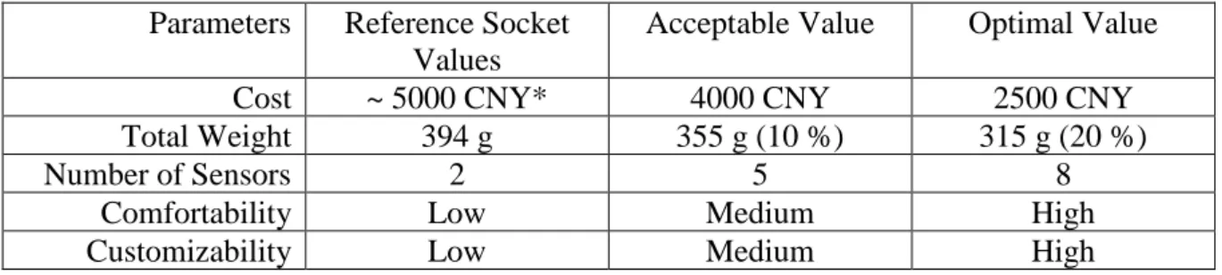
Table 3: Specification of requirements.
Parameters Reference Socket Values
Acceptable Value Optimal Value
Cost ~ 5000 CNY* 4000 CNY 2500 CNY
Total Weight 394 g 355 g (10 %) 315 g (20 %)
Number of Sensors 2 5 8
Comfortability Low Medium High
Customizability Low Medium High
*Cumulative cost value.
4.7 The Method of Reverse-Engineering a Residual Limb
This section involves the observation of the current process and investigates alternative methods of reverse-engineering a residual limb.
Today, the OYMotion does not manufacture prosthetic sockets, their main product is the “OHand” which is a mechanically actuated hand prosthesis controlled by EMG technology. By examining the manufacturing process of the existing socket that is available today it has been observed that the method used for capturing the shape of the residual limb is orthopedic casting, which involves that a prosthetic technician using gypsum and wraps it around the residual limb. This process takes 2.5 hours in total including about 15 minutes for the gypsum to dry and resemble the positive shape of the residual limb.
Investigating the current socket manufacturing method can provide adequate information about potential areas of improvement by using alternative methods to refine the process and increasing overall efficiency and effectiveness.
4.8 Current State of Socket Manufacturing
30 (104)
4.8.1 Current Price Model
The research findings on the price model of the Ottobock socket was based entirely on the experience and estimation of Hualiang Ni, since the information regarding the costs is not transparent and is not publicly available in China and differs from the rest of the world. It is suggested that this is due to government fixed prices.
If the prosthetic component is paid for by the government health care system, then the price of the socket remains unknown. In the case where it is paid for by the end-user, different price ranges can be expected. The reason behind the price variation is that when the end-user is responsible for the cost, the end-user can choose between different materials or other
customization options since the manufacturing process is treated as a service and as a result, the finished socket would be better. The authors visited a clinic where a socket was made by a technician for Mr. Wang and it was similar with the standard Ottobock socket except it had eight sensor placements instead of two for increased functionality with OHand.
The price model of the final product, meaning a socket equipped with sensors, hardware, batteries, and the OHand prosthetic can reach up to ~50 000 CNY along with rehabilitation programs and perhaps precalculated after-sales maintenance costs or other miscellaneous costs.
The price estimation of the manufacturing cost component is ~2000 CNY not including the technician. The technician cost component is calculated by an estimated ~80 CNY per hour in salary alone. The addon cost of the technician is estimated at ~200 CNY for cost addons such as value-in-use of the machines, the share of the clinic, and the material costs.
4.8.2 Orthopedic Casting Process
Through participation in a demonstration of orthopedic casting with the technician, and Mr. Wang the individual with below-elbow dual amputation. The orthopedic casting can be described by following the procedure’s different phases. Throughout the casting process, the technician makes observations and inquiries about the overall comfort of the cast, ensuring that it is made correctly and with acceptable level of comfort.
The first phase involves wrapping the gypsum around the amputated area until slightly above the elbow. Then the technician also cuts some part of the gypsum near the elbow joint since it is important to allow 180° degrees of elbow extension. This part creates a tradeoff in the mold’s grip making it less tight.
31 (104) Figure 9: The technician, removing parts around the elbow joint.
Then, the technician allows the gypsum to harden, and this is done with the amputated individual’s elbow fully flexed in order to keep the muscles in place.
Once the cast gypsum has hardened, the next phase involves making holes in the gypsum near the areas previously marked to have strong nerve muscles. These areas will later be used for placement of the sensors. The technician then checks to ensure that these holes are located correctly.
The technician adds extra padding, especially near the elbow area of the gypsum, this exact same shape will later be used to make the socket and therefore it is of critical importance that the padding makes the mold stable and durable.
Since the amputated individual has a dual below-elbow amputation, it is required by the technician to make two sockets considering the manufacturing method in addition to typical body asymmetry. The molds can be identified as left and right arm by looking at the elbow joint. The elbow joint has a bigger bone that is always closer to the body, and therefore can be used to distinguish left from right.
32 (104) Figure 10: The socket after the technician had bored eight concentric holes based on marks where the sensors are going to be placed.
In the third phase, the technician takes the gypsum cast to a workshop to bore holes for the sensors, this is done concentric with the previous holes. This gypsum cast is different, since normally only two holes would be made to hold two sensors, but this one has eight holes made for implementation of eight sensors. However, a lot of the gypsum is removed in the process.
4.8.1 Fabrication of EVA Plaster Mold
The single-use mold that has been made in the orthopedic casting process will be used for fabrication of the prosthetic socket.
The fabrication of an ethylene-vinyl-acetate (EVA) plaster mold involves using the single-use gypsum mold from the casting process to make an initial plaster mold for testing. Once it is finished, it is again fitted to the intended end-user. The final plaster mold is then created by vacuuming and then baking it in an oven. It is then allowed to cool for two to three hours before finally refining its edges and surfaces. Then the plaster mold will be used as a reinforcement layer in the following lamination process.
33 (104)
4.8.2 Lamination Process
Prosthetics manufacturer Ottobock supplies in China, and the design of this socket is from Ottobock. The prosthetic socket material used in the lamination process is called Orthopox lamination resin which is an epoxy-based resin.
Figure 11: A canister of Orthopox epoxy resin from ottobock.
the plaster mold is used as a reinforcement, fitting a stocking net over the reinforcement wall, and placing a space filler, then mixing resin and pouring it into the filler allowing it to be absorbed by the net. The resin is given time to harden and the space filler is removed. Further refinement is then made on the residual limb compartment.
The socket adapter which is the interface between the residual limb compartment and the prosthetic hand also shares the same material but is created in advance with one standard size and later is fitted to the end-user’s measurements.
In the next process, the socket is then attached and fastened with screws together with the socket adapter which houses components such as the Li-ion battery.
4.8.3 Installment Process
This installment procedure requires the amputee to be present and involves the adjustment and fitting of the produced socket to the user and installment of other systems. Among the systems that are installed in this process are the sensors. Information about the sensors optimal
placement have been collected earlier while doing the gypsum mold, so the sockets have an indent where the sensors are going to be placed.
When the sensors have been installed, the technician proceeds to mount the hand-prosthesis onto the socket. This step involves not only the mounting of the hand-prosthesis, but also tuning it to its intended user, which can take considerable time. The process of fitting the
34 (104) socket and installing the sensors can take 2.5 hours. Once the hand-prosthesis has been
mounted, the technician proceeds to tune it which could either be done relatively quickly or take quite a lot of time. It depends on the hand-prosthesis used, the ones that are simpler in functionality are not complicated to tune but for other hand-prostheses such as the OHand that have more complex functionality, it can take much longer. (Ni, 2019)
4.9 Additive Manufacturing Process
This section covers a different approach to socket manufacturing through additive
manufacturing methods. An experiment was performed to determine the practical use of 3D-scanning a residual limb and investigate the potential benefits with additive manufacturing.
Figure 12: Comparison of mirroring processes of 3D-scanning and orthopedic casting.
Experiments were conducted by investigating how good the 3D-scanning technique may be compared to prosthetic casting. The experiment involved scanning one of the author’s arms using a 3D scanner called Artec Space Spider (artec3d, 2019). In this experiment, the authors wanted to investigate whether it is possible to fully replace orthopedic casting with the implementation of a 3D-scanner and if so, how well the result will hold in comparison to traditional methods.
Artec Space Spider is a product of the company Artec 3D which allows for maximum precisions up to 0.05 mm. The product specification states that the product can be applied in the field of health care and is highly suitable for orthopedic, prosthetic, plastic surgery and adapted wheelchairs. What distinguishes Artec Spider from other scanners is precisely the process of shaping the exact 3D-model within a very short time. The product can scan one million points per second (artec3d, 2019). Other parameters, such as availability, played a
35 (104) significant role in why the authors chose this product in this research. The 3D scanner was available for use in the Material lab of Mälardalen University, Eskilstuna.
Figure 13: The workflow procedure of Artec Spider Space 3D-scanner.
The 3D scan can be a more sustainable method of being able to save end-user data compared to prosthetic casting. This digital data that is unique to each end-user can be stored
indefinitely at the company. End-user data can also be used to develop future prostheses designs.
Table 4: Parameters and limitations of the 3D-scan.
Parameters Limitation Time-lapse per scan 1 min – 30 min Max Read Error 0,1 – 0,4 mm RAM per scan 0 MB – 100 MB
In an experiment, the authors attempted to 3D scan the arm of one of the authors, which would then be further processed to represent a residual limb as closely as possible. After several attempts, the authors could not attain a 3D scanned image with satisfactory accuracy,
36 (104) because the arm is not an inanimate object. The 3D scanner has a reading capability of up to one million reading points per second, and it can lead to a slight movement of the scanned objects affecting scanner read-out errors. The larger the size of the object, the more memory it can take for the software to save all the data.
In other tests, the authors attempted to design a three-dimensional object that would represent the amputee's residual limb. The picture below shows the restored model. The authors used the latest version of the Artec Studio Professional 13 software to complete the scanning process.
Figure 14: A test print of the scan performed by Artec Space Spider.
The 3D scan can show read errors and inaccuracies in the scanned image which can be used as a measurement on how accurate the read has become. The picture below shows that the maximum read error 0.3mm, which indicates that the scan is not performed with the best possible accuracy. Moreover, the least possible read error is 0.1mm.
In total, the scan shows how much storage each scan requires. The size of the file is
proportional to the time-lapse of the scanning process. The maximal error in each scan can indicate how the physical model can differ from the real object.
37 (104) Figure 15: The Artec-Spider span interface.
Figure 16: Scanning progress and maximal read errors are shown in the workspace.
The color of an object and the distance between the object and the scanner, determines how accurate the scan will be.
The scan works optimally with an inanimate, non-moving object in contrast to a human arm which is a biologically moving object, and as such poses a challenge in making high accuracy scans.
38 (104)
4.9.1 The Additive Manufacturing Method
Advantages of orthopedic casting are that the method is not particularly advanced in application since the materials for producing the casted model are readily available. 3D scanning is a technique that presents an alternative process for prosthetic casting. The
measurable parameters attainable with this technology are not found in orthopedic casting and as such opens new areas of possibilities.
Digital Mechanics® is a company in Västerås that produces designed products and prototypes through additive manufacturing. A study visit was conducted at the company, and the
company's CEO manager Fredrik Finnberg went through the company's production system and available manufacturing methods. (Digital Mechanics, 2019)
HP’s recently launched 3D printer Multi-Jet Fusion technology is one of the fastest AM methods with PBF technology compared to other PBF 3D printing methods. This technology can produce complex geometries with the highest production speed and with an almost negligible price difference from SLS printing.
Figure 17 shows a 3D-printed gear made from Nylon Pa 12.
Figure 17: A Nylon PA12 gear made using the MJF technique.
39 (104) Figure 18: Process workflow of the AM manufacturing process.
The measurable parameters of each step in the manufacturing process, current state process and in the AM process, are shown in table 5.
40 (104) Table 5: Side-by-side of each step in the manufacturing processes and their respective time-lapses.
Current State of the Manufacturing
Processes
Estimated time-lapse (h)
AM processes Estimated time-lapse (h)
Orthopedic casting 2.5 Scan preparation 0.5
Positive mold and refining
1.5 3D scanning 0.5
Fabrication of EVA plaster model for
testing
1.0 Use of Meshmixer 1.0
Final plaster model casting
1.0 Export to CAD
software and
post-processing 1.0 Plaster cooling 2.0 HP MJF 3D-printing* 72 (3 business days)* Plaster refining (hole clearances and edges) 1.0 Adjustment and fitting 1.0 Lamination process and refining 2.0 Assembly process (sensors and OHand) 1.0 Adjustment and fitting
2.5 Tuning of OHand N/A**
Assembly (socket adapter, sensors and
OHand)
2.5
Tuning of OHand N/A**
* The HP’s MJF 3D printing process, is an outsourced process. In addition, it is a fully automated process.
**For a traditional low-end prosthetic hand, the tuning is quite simple due to simple functionality. This research uses parameters based on the OHand prosthetic which has more complex functionality. Regardless, the time spent tuning OHand does not affect the socket manufacturing processes since its shared.
4.10 EMG Sensor Arrangement
Sensor placement is an important function since a requirement for the EMG sensors to work at optimal conditions is that they are in contact with skin and positioned where the nerve-muscles are strongest. Suboptimal placement could render the whole prosthetic socket underperforming or useless. Therefore, different techniques that aim to locate strong nerve-muscles need to be assessed.