eVALUE 1 ICT-2007-215607
eVALUE-101115-WP2-D22-V20-FINAL.doc
Testing and Evaluation Methods for ICT-based Safety Systems
Collaborative ProjectGrant Agreement Number 215607
Deliverable D2.2
“SPECIFICATIONS LIST”
Confidentiality level: Public Status: Final
Executive Summary
eVALUE is addressing active safety functions and their capability to perform through two courses of action: defining and quantifying the requirements of a safety function under a relevant traffic accident scenario and developing the testing and evaluation methods for the active safety functions of vehicles.
WP2 aims at developing testing procedures based on the system descriptions and scenarios defined in WP1. The testing procedures will be integrated in WP3 and finally carried out and assessed in WP4.
D2.2 takes the output of D2.1 and, where scenarios, safety functions and test procedures are related, defines the basis for the test procedures further developed in the next work packages. The test procedures are drafted, taking into account the future ―testing protocols‖ and the ―assessment protocols‖.
The document is structured according to the scheme followed from the project start, where tests are classified into ―Design Reviews‖, ―Physical Testing‖ and ―Laboratory Testing‖. The test procedures are also classified depending on clustering different safety functions: ―Longitudinal Assistance‖, ―Lateral Assistance‖ and ―Stability‖.
eVALUE 2 ICT-2007-215607 eVALUE-101115-WP2-D22-V20-FINAL.doc Document Name eVALUE-101115-WP2-D22-V20-FINAL.doc Version Chart
Version Date Comment
0.0 20/04/09 Draft version created by IDIADA
0.1 25/05/09 Updated version, with all partners contribution 0.2 18/06/09 SP reviewed version
0.3 01/07/09 Draft updated version
0.4 07/07/09 Draft version reviewed by all partners 0.5 15/07/09 Final version reviewed by all partners 0.6 17/07/09 Final version accepted by all partners 1.0 22/07/09 Final version as submitted to the EC 2.0 15/11/10 Final version including EC comments
Authors
The following participants contributed to this deliverable:
Name Company Chapters
A. Aparicio, S. Baures,
J.M. Dalmau IDIADA all
H. Eriksson, J. Hérard,
J. Jacobson. SP 2, 3.2, final revision
N. Bilbao, L. Isasi , M.
Larburu, J. Sánchez RBTK 4, 5, 6
H. Karsten, A. Karlsson,
S. Leanderson VTEC 3.5, 4, 5, 6
Q. Huang, M. Lesemann,
J. Lützow, A. Zlocki IKA 3.4
I. Camuffo, M. Vesco CRF 3.5, 3.6
F. Bruzelius VTI 3.6
Coordinator
Dipl.-Ing. Micha Lesemann
Institut für Kraftfahrzeuge - RWTH Aachen University Steinbachstraße 7, 52074 Aachen, Germany
Phone: +49-241-8027535 Fax: +49-241-8022147
E-Mail: lesemann@ika.rwth-aachen.de
Copyright
eVALUE 3 ICT-2007-215607 eVALUE-101115-WP2-D22-V20-FINAL.doc Table of Contents 1 INTRODUCTION ... 6 1.1 Motivation ... 6 1.2 Concepts followed ... 6
1.3 Testing strategies for preventive safety systems ... 8
1.4 Status of the test procedures ... 11
2 DESIGN REVIEW ... 13
2.1 Introduction ... 13
2.2 Aims and goals with Design Reviews... 14
2.3 Specifications for Design Review of Definition of Subject Vehicle ... 14
2.4 Specifications for Design Review of Environmental Conditions ... 15
2.5 Specifications for Design Review of HMI Design ... 16
2.6 Specifications for Design Review of Functional Safety ... 16
2.7 Next steps in Design Review ... 17
3 PHYSICAL TESTING ... 18
3.1 Introduction ... 18
3.2 Definitions, measurements and safety indicators ... 18
3.2.1 Definitions and measurements ... 19
3.2.2 Safety indicators ... 20
3.2.2.1 Suitable for cluster 1 ... 21
3.2.2.2 Suitable for cluster 2 ... 22
3.2.2.3 Suitable for cluster 3 ... 23
3.3 Instrumentation of the vehicles ... 25
3.4 Specifications for Physical Tests of cluster 1 ... 28
3.4.1 Introduction ... 28
3.4.2 Aims and goals with physical testing in cluster 1 ... 28
3.4.3 Test Procedures for Physical Tests of cluster 1 ... 29
3.4.3.1 Test Procedure C1-1&2#1 Deceleration of target vehicle ... 29
3.4.3.1.1 Test Procedure description ... 29
3.4.3.1.2 Test Procedure implementation ... 30
3.4.3.1.3 Test Results analysis ... 30
3.4.3.2 Test Procedure C1-1&2#2 Approaching a slower or stationary target vehicle 31 3.4.3.2.1 Test Procedure description ... 31
3.4.3.2.2 Test Procedure implementation ... 31
3.4.3.2.3 Test Results analysis ... 32
3.4.3.3 Test Procedure C1-3#1 Transversally moving target ... 32
3.4.3.3.1 Test Procedure description ... 32
eVALUE 4 ICT-2007-215607
eVALUE-101115-WP2-D22-V20-FINAL.doc
3.4.3.3.3 Test Results analysis ... 34
3.5 Specifications for Physical Tests of cluster 2 ... 34
3.5.1 Introduction ... 34
3.5.2 Aims and goals with physical testing in cluster 2 ... 35
3.5.3 Test Procedures for Physical Tests of cluster 2 ... 35
3.5.3.1 Proposed scenarios to be analysed ... 35
3.5.3.2 Test Procedure C2-1to6#1 Lane and road departure ... 35
3.5.3.2.1 Verification test procedure description ... 36
3.5.3.2.2 Validation test procedure descriptions ... 37
3.5.3.3 Test Procedure C2-7#1 Lane change collision avoidance on a straight road 39 3.5.3.3.1 Verification test procedure description ... 39
3.5.3.3.2 Validation test procedure descriptions ... 40
3.6 Specifications for Physical Tests of cluster 3 ... 42
3.6.1 Introduction ... 42
3.6.2 Aims and goals for physical tests of cluster 3 ... 43
3.6.3 Test Procedures for Physical Tests of cluster 3 ... 43
3.6.3.1 Test Procedure C3-1#1 Mu-split braking ... 43
3.6.3.1.1 Test Procedure description ... 43
3.6.3.1.2 Test execution ... 44
3.6.3.1.3 Test Results analysis ... 44
3.6.3.2 Test Procedure C3-2#1 Collision avoidance ... 44
3.6.3.2.1 Test Procedure description ... 44
3.6.3.2.2 Test execution ... 45
3.6.3.2.3 Test Results analysis ... 45
3.6.3.3 Test Procedure C3-3#1 Fast driving into a curve scenario ... 46
3.6.3.3.1 Test Procedure description ... 46
3.6.3.3.2 Test execution ... 46
3.6.3.3.3 Test Results analysis ... 47
3.6.3.4 Test Procedure C3-4#1 Rollover scenarios ... 47
3.6.3.4.1 Test Procedure description ... 47
3.6.3.4.2 Test execution ... 48
3.6.3.4.3 Test Results analysis ... 48
3.7 Next steps in Physical Testing ... 48
4 LABORATORY TESTING ... 50
4.1 Introduction ... 50
4.2 Aims and goals of the Laboratory Tests ... 50
5 DRIVING SIMULATOR STUDIES ... 52
5.1 Introduction ... 52
5.2 Aims and goals ... 52
5.3 Specifications for Driving Simulator studies ... 52
5.3.1 Obtaining input parameters for physical tests ... 53
eVALUE 5 ICT-2007-215607
eVALUE-101115-WP2-D22-V20-FINAL.doc
5.4 Scenarios to be analysed with Driving Simulator ... 57
5.4.1 Cluster 1: Scenarios for Driving Simulator ... 58
5.4.1.1 Scenarios C1-1&C1-2: Straight road and curved road ... 58
5.4.1.2 Scenario C1-3: Transversally moving target ... 59
5.4.2 Cluster 2: Scenarios for Driving Simulator ... 59
5.4.2.1 Scenarios C2-1, C2-2, C2-3, C2-4, C2-5 & C2-6: Lane/Road departure on a straight road/curve ... 59
5.4.2.2 Scenarios C2-7: Lane change collision avoidance in a straight road ... 59
5.5 Next steps in Driving Simulator studies ... 60
6 CONCLUSIONS ... 61
6.1 Conclusions related to Design Reviews ... 61
6.2 Conclusions related to Physical Tests... 61
6.3 Conclusions related to Laboratory Tests ... 61
6.4 Conclusions related to Driving Simulator studies ... 61
7 GLOSSARY ... 63
8 REFERENCES ... 64
9 ANNEX I – Testing Protocols for Design Reviews ... 66
APPENDIX 1. CHECKLIST Type of Vehicle ... 74
APPENDIX 2. CHECKLIST Longitudinal Functionality ... 76
APPENDIX 3. CHECKLIST Lateral Functionality ... 80
APPENDIX 4. CHECKLIST Stability Functionality ... 84
APPENDIX 5. CHECKLIST External Communication ... 87
APPENDIX 6. CHECKLIST ENVIRONMENTAL CONDITIONS ... 96
APPENDIX 7. CHECKLIST HMI DESIGN ... 106
APPENDIX 8. CHECKLIST FUNCTIONAL SAFETY ... 124
9 ANNEX II – Review of possible safety indicators for cluster 1 and 2 ... 127
eVALUE 6 ICT-2007-215607
eVALUE-101115-WP2-D22-V20-FINAL.doc
1 INTRODUCTION 1.1 Motivation
The general objective of eVALUE is to develop testing and evaluation procedures for Information and Communication Technologies (ICT)-based safety systems and, thereby, to increase public perception and customer acceptance of ICT-based safety systems and to support development of ICT-based safety systems at vehicle OEMs and suppliers.
The objective of Work Package 2 (WP2) in eVALUE is to provide specific test procedures for representative accident scenarios and integrate them into general procedures (WP3 objective) for global performance assessments and evaluations (WP4 objective). For this reason, WP2 is providing many test procedures that might overlap and need to be integrated in the future work packages.
In other words, the specific objective of WP2 is the definition, development and analysis of test and evaluation procedures for all different situations selected as the focus of eVALUE (defined in WP1).
This can be divided into 2 objectives:
• Assignment of testing procedures to accident scenarios.
• Definition and detailed development of testing and evaluation procedures for scenarios.
D2.1 fulfilled the first objective, while D2.2 is compiling all the results of WP2 and completing the remaining objective.
One of the major achievements shown in D2.2 is the definition of the safety indicators. For each of the three clusters (longitudinal domain, lateral domain and vehicle stability), a selection of variables able to show the performance of a vehicle under specific condition has been done. These safety indicators are aimed to be the basis of the test procedures, which are defined according to them.
1.2 Concepts followed
D2.2 describes the status of eVALUE after 18 months of work. For this reason, it is important to refresh which are the concepts followed within the project, regarding the approach, the types of tests and the test procedures. This chapter tries to compile this information.
Objectives
The main focus of the European research project “Testing and Evaluation Methods for ICT-based Safety Systems (eVALUE)” is to define objective methods for assessment of preventive safety systems. Performance test results presented to the public will help to promote the use of those systems. The project is based on safety systems used in today‟s vehicles and will investigate the future upcoming ICT-based systems. Aims are to identify evaluation and testing methods, especially for primary safety systems, with respect to the user needs, the environment and economic aspects. Tests are preformed with respect to verification and validation of the preventive safety of the vehicle.
• Verification is addressed by tests of a function towards its requirements and considers the course of events from creating a critical situation until system activation occurs. Available reference material in terms of e. g. ISO standards can be used. • Validation is provided by tests for evaluating safety effects; investigation on whether a
eVALUE 7 ICT-2007-215607
eVALUE-101115-WP2-D22-V20-FINAL.doc
increasing safety. For this purpose driver in the loop testing is required to consider both, the response from the vehicle and/or the driver. Less reference material is available for deriving these tests, for instance with respect to information on driver behaviour, indicators for reflecting safety performance (safety indicators) as well as methods and tools for including drivers in the tests.
Scenario based approach
The actions of the project have been defined following a scenario based approach, opposed to the system based approach.
• With the scenario-based approach, it is started from accident databases to make assumptions on the most relevant and critical accidents in order to develop test methods for these situations. The advantage is that the focus is the most crucial accident types, derived from real world accident data. Thus performance will be evaluated in traffic scenarios, not adapted to specific function. This approach might lead to that certain systems are found to contribute more than others in increasing safety in the particular situations addressed, which might stimulate development of these systems.
• With the system-based approach traffic scenarios are defined for specific systems, where each system is assigned to certain traffic scenarios. A consequence here is that the accident types are not prioritized or ranked after criticality or importance to end up in a few general test scenarios, independent of all safety systems. All systems are assigned a set of relevant traffic scenarios and these traffic scenarios are more specific and adapted to the systems they are addressing.
Clustering
The ICT-based safety systems have been classified into four domains. Each domain will have several test procedures. These test procedures might be relevant to test several safety functions.
• Longitudinal assistance: Adaptive Cruise Control, Forward Collision Warning and Collision Mitigation by Braking.
• Lateral assistance: Blind Spot Detection, Lane Departure Warning and Lane Keeping Assistant.
• Yaw/stability assistance: ABS and ESC.
• Additional assistance: is excluded from the eVALUE project
Test procedures
It is important to note that the test procedures will be developed from a scenario based point of view. It means that no test procedures will be defined for specific systems. Test procedures will be defined for clusters, represented by accident scenarios. The objective is the evaluation of the behaviour of a vehicle under representative accident conditions and avoiding tests which are designed for the validation and verification of a function of the vehicle.
Test procedures have been classified into: • Design reviews
It is a systematic, comprehensive, and documented analysis of a design to determine its capability and adequacy to meet its requirements. It is also suitable to identify present and potential problems.
• Laboratory tests
This type of tests can be divided into system performance and human factors testing in a driving simulator. A laboratory test is carried out on a static environment and is meant to identify and determine the concepts, requirements, specifications and limitations of the safety systems and components in the subject vehicle, in order to create a set of valid test procedures for the physical vehicle tests. Driver in the loop is considered under this type of test on a simulator environment. The test results
eVALUE 8 ICT-2007-215607
eVALUE-101115-WP2-D22-V20-FINAL.doc
derived from the laboratory test will set the range input parameters for the physical vehicle test.
• Physical tests
The purpose of this type of test is to validate the complete vehicle‟s performance, following the scenario approach. In other words, the approach is not to test one particular ICT-based safety system, but to validate the whole vehicle‟s functional safety under different scenarios. The general approach of eVALUE, based in real accident scenarios, is emphasized in physical testing, where there is a clear implementation of real traffic scenarios.
For each cluster, representative accident scenarios have been defined and safety indicators have been identified. The test procedures will show how to test and assess these safety indicators under the related clusters.
Another important aspect is the differentiation between verification and validation.
1.3 Testing strategies for preventive safety systems
The primary goal with preventive safety systems is to increase the safety for the occupants in a vehicle as well as for other road users. The purpose with ICT-based safety systems is to detect a critical event and support the driver in the primary driving task by taking an action during the chain of events that follows. The support to the driver can be given in different ways depending on the type of system. An information or warning system aims at increasing the driver‟s attention and awareness of the critical situation. The outcome of the situation depends on the driver‟s response to the given warning or information. An intervening system will provide, possibly in addition to the warning, an active response from the vehicle; an intervention that aims at retaking control over the situation. The driver might be more or less aware that the intervening function is taking an action. The intervention can either be complementary or contradictory to the driver‟s action.
Regardless of the type of function, the purpose of preventive safety systems is to act at some point in the chain of events following a critical event in such a way so that the criticality of the events is minimized and the safety is increased.
Within the scope of eVALUE are warning, support and intervention systems. One of the challenges is how to consider driver‟s behaviour in the tests procedures.
ADAS vs. IVIS systems
Since the objective of D2.2 is to define testing and evaluation methods for ICT-based safety systems or preventive safety systems, it is important to find a suitable way to describe the targeted functions.
A general distinction is often made between ADAS (Advanced Driver Assistance System and IVIS (In-vehicle Information Systems). In general, there seems to be a consensus that ADAS refer to systems mainly intended to support the (primary) driving task, while IVIS are systems mainly supporting other (secondary) tasks.
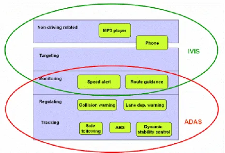
In AIDE a framework, based on the hierarchical control model of driving ECOM (Extended Control Model) (AIDE D2.2.5 e.g. Hollnagel, Nåbo and Lau, 2003; Hollnagel and Woods, 2005; Engström and Hollnagel, 2005), was used, describing the functions in terms of the driving sub-task (i.e. which goal) that they support (where some systems may not support driving goals at all). In this context, it is more useful to talk about functions than systems, since a system may contain many functions of very different types. A tentative mapping of some example IVIS and ADAS functions onto the ECOM layers is illustrated in Figure 1. This
eVALUE 9 ICT-2007-215607
eVALUE-101115-WP2-D22-V20-FINAL.doc
taxonomy is intended as a complement, rather than as an alternative, to the more traditional taxonomy of IVIS and ADAS (AIDE D2.2.5 Floudas et al., 2004)
Figure 1: Proposed mapping of the ADAS/IVIS categories and some example functions onto the ECOM layers according to AIDE D2.2.5
.
Concepts of performance testing
The evaluation of the functional performance of a preventive safety system needs to consider both the technical performance of the function as well as the overall safety effects of the function.
The technical performance tests aims at investigating whether the function equipped in the vehicle provides a correct behaviour with respect to technical specifications on what the function shall do. This can be referred to as verification tests against technical requirements. Evaluation of the overall safety effects of a function aims at investigating that the function fulfils its purpose; that is, given a certain output from a function the overall response produce the desired outcome in this case increased safety. This can be referred to as validation tests of the overall safety effects. Since no general established references for evaluating safety exist, is not trivial in what way to define assessment criteria for evaluating safety effects from a set of test results. An important part of the test strategy is therefore to define safety indicators that can be used for reflecting safety. Other important steps are to define the test objective and the hypothesis: what it is that eVALUE wants to test and which are the intended effects?
The driver‟s behaviour and response are essential when testing the safety effects of preventive safety systems, in particular for warning and information systems. Figure 2 presents the difference and connection between verification and validation, also previously presented in D1.2. Indicators for analysing the results will differ depending on whether the focus is verification or validation.
eVALUE 10 ICT-2007-215607 eVALUE-101115-WP2-D22-V20-FINAL.doc Technical performance VERIFICATION Acceptance Usability Safety effects VALIDATION Intention: Driver reaction Safety indicators
•Lane departure (yes/no) •Duration of lane excursion •TTC
Driver´s reponse needs
to be included Safety impact
Technical indicator:
•Timing of warning
Is safety increased with the system?
Figure 2: Validation vs. Verification Driver in the loop testing
Depending on what safety system the vehicle is equipped with, the driver will be more or less involved in the vehicle‟s overall response. The overall outcome from an activation of a warning systems like Forward Collision Warning (FCW) system or Lane Departure Warning systems (LDW) entirely depends on the drivers reaction to the system and the driver‟s acceptance of the warning, while a supporting system as for example a Lane Keeping Assistance system (LKA) to largest extent relies on the driver‟s reaction, but might also have some intervening action from the vehicle itself, for instance by applying a torque in the steering wheel. For other preventive safety systems like ABS or ESP with autonomous intervention, the vehicle itself provides the complete corrective manoeuvre for taking control of the situation. However also in these situations and for the intervention systems, the driver‟s reaction during the critical event is of importance in order to understand in what way the driver can influence the overall outcome of the situation.
When performing validation tests with drivers one challenge is to define a reference or baseline for evaluating safety effects. When evaluating technical performance, it is most likely to have a certain specification on how the function will behave, for analysis of the results. Also when evaluating safety effects it is needed to have a reference for the test when analysing the data. This reference is often called baseline when performing driver tests. One possibility for creating a baseline for comparison is to perform driver tests with and without the safety system equipped. A problem with this strategy is that it is not easy to create a critical situation in a real test environment without the safety system equipped for safety reasons. A recently published report from NHTSA; Methodology for estimating safety
benefits for Preproduction Driver Assistance Systems (Burgett et al, 2008) presents a
methodology for estimating safety effects using naturalistic driving data from a recently conducted field operational test (FOT), in combination with driver tests in similar situations as found in the FOT data, but with safety functions installed in the vehicles. This methodology is of great interest when considering driver tests in eVALUE.
eVALUE 11 ICT-2007-215607
eVALUE-101115-WP2-D22-V20-FINAL.doc
simulator, in which you can create critical scenarios in a repeatable way with similar prerequisites for many drivers. To test these driver behavioural effects when driving with intervention systems in a driving simulator brings another dimension of complexity in a driving simulator since a representative vehicle dynamics model and characteristics for achieving the right prerequisites is needed for the tests.
Driver in the loop testing is further discussed in the chapter driving simulator tests. Most of the challenges with driver tests discussed in this chapter are also applicable for physical testing with drivers.
eVALUE scope
The eVALUE scope is mainly to investigate performance testing methods that can be carried out in a physical environment both with respect to verification and validation. Within WP3 testing protocols will be derived focusing on either verification or validation.
Verification tests are naturally performed in a physical environment, in which the vehicle and function acts under natural environmental conditions and vehicle dynamics prerequisites. Validation tests for evaluating safety effects might be performed in a physical environment or in a driving simulator depending on the purpose with the test and the type of system (warning, support or intervention).
Driver tests on test track and in driving simulator both have drawbacks and advantages. Test in a physical environment will provide a more realistic test environment but it will on the other hand be difficult to create critical scenarios for safety reasons. It will also be difficult to assure repeatability of the tests and tools for performing driver tests such as dummy vehicles might not appear realistic to the driver. In a driving simulator you might get other effects because of the virtual environment.
A current large research area is driver modelling which is an important and interesting input and complement to the eVALUE project for understanding driver‟s behaviour. Other related research projects are the currently ongoing field operational test (FOT´s) projects which aim at collecting data on driver‟s behaviour.
1.4 Status of the test procedures
Not all the test procedures have the same level of development and not all the types of test have the same number of test procedures. A scheme of what is provided in this deliverable is given as a reference.
• Design reviews
Test procedure for Definition of subject vehicles Draft test protocol
Draft checklist for type of vehicle
Draft checklist for longitudinal functionality Draft checklist for lateral functionality Draft checklist for stability functionality Draft checklist for external communication Test procedure for Environmental conditions
Draft test protocol
Draft checklist for environmental conditions Test procedure for HMI design
Draft test protocol
eVALUE 12 ICT-2007-215607
eVALUE-101115-WP2-D22-V20-FINAL.doc
Test procedure for Functional safety Draft test protocol
Draft checklist for functional safety • Physical tests
o Cluster 1
Description, implementation and assessment for the test procedure for deceleration of target vehicle
Description, implementation and assessment for the test procedure for approaching a slower or stationary target vehicle
Description, implementation and assessment for the test procedure for transversally moving target
o Cluster 2
Description, implementation and assessment for the test procedure for lane and road departure
Description, implementation and assessment for the test procedure for lane change collision avoidance on a straight road
o Cluster 3
Description, implementation and assessment for the test procedure for mu-split braking
Description, implementation and assessment for the test procedure for collision avoidance manoeuvre
Description, implementation and assessment for the test procedure for fast driving into a curve
Description, implementation and assessment for the test procedure for rollover
• Laboratory tests
o Component tests
Specifications list for component tests • Driving simulator tests
o Specifications list for driving simulator tests
It is important to understand that WP2 has to provide a specification list of all the test procedures, which is already done in this document. The development of the final test procedures will be done in WP3 and WP4.
eVALUE 13 ICT-2007-215607
eVALUE-101115-WP2-D22-V20-FINAL.doc
2 DESIGN REVIEW
A design review is a systematic, comprehensive and documented analysis of a design to determine its capability and adequacy to meet its requirements. A design review also serves to identify present and potential problems. Most parts of the design review are done studying the documentation and interviewing the manufacturer, but other parts of the work might be done investigating the vehicle.
2.1 Introduction
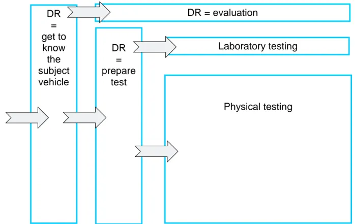
A design review may be performed with one out of three different objectives (see Figure 3) The first objective for a design review would be to familiarize with the subject vehicle. Efficient performance testing will require the test engineer to understand the safety functionality of the vehicle. The design principles of the ICT-based safety systems should also be understood, even if the performance testing does not explicitly address the performance of individual systems. Such a “get-to-know” design review would include a definition of the subject vehicle, an overview of longitudinal functionality, an overview of lateral functionality, an overview of stability functionality, and external communication needs. The second objective for a design review would be to prepare a test. The test cases of the performance testing will partly be chosen depending on potential weaknesses of the system and on the already performed test by the manufacturer. An example of such a design review is for system performance in different environmental aspects (rain, snow, ice, darkness etc.). The performance at different environmental influences may be reviewed and assessed instead of thoroughly tested at the performance testing. The manufacturer must be able to show the efforts made during development testing of user behaviour and environmental conditions. “Normal conditions” (dry asphalt or concrete, flat road, approx 20 °C) would then suffice at the performance testing.
The third objective for a design review will be to actually perform an evaluation reaching a pass or a fail judgement. The design review will be part of the safety evaluation. The interface to the driver (human-machine interface, HMI) will probably be reviewed and assessed by a small number of experts. A time-consuming HMI test with a large number of drivers cannot be afforded at the performance testing. The focused HMI design review by experts will conclude if the HMI is “pass” or “fail” in the performance testing.
eVALUE 14 ICT-2007-215607
eVALUE-101115-WP2-D22-V20-FINAL.doc
Figure 3: Objectives to perform a Design Review (DR)
2.2 Aims and goals with Design Reviews
As stated above, a design review is a practical document able to give some information about the vehicle to be tested and able to indicate some failures or bad practices implemented in the vehicle, a priori, before any test is implemented.
An issue related to Design Reviews is the need of having a close contact with the vehicle manufacturer. Some of the information required can be obtained by simply inspecting or driving the vehicle but, for some other, it is needed to contact the manufacturer. At some points, information might not be easy to get, because it could be sensitive, confidential or because the manufacturer would not find the necessity of sharing it. This issue is not completely in the scope of eVALUE and, at least, not at the level of WP2, but some concerns have been arisen. Thinking in a future „eVALUE Test Programme, an effective manner could be defining a collaboration bonus, but this will be discussed in the next work packages.
2.3 Specifications for Design Review of Definition of Subject Vehicle
It is important to clearly identify the vehicle under test (i.e. the subject vehicle), especially if the vehicle is a prototype vehicle. All major characteristics of the vehicle influencing the performance testing must be noted. The challenge of identifying the vehicle under test is greater at performance testing than at testing of passive safety. Even small design modifications in the active safety systems may severely influence the performance.
A certain model of a road vehicle is normally produced in several different types. There will be differences in engine, chassis, brakes etc. Many of these differences will not be important for the performance testing. It will in many cases be possible to choose one type of vehicle
DR
=
get to
know
the
subject
vehicle
DR = evaluation
DR
=
prepare
test
Laboratory testing
Physical testing
eVALUE 15 ICT-2007-215607
eVALUE-101115-WP2-D22-V20-FINAL.doc
for the performance testing, and to assume that the test results are valid also for other types of the same vehicle.
Evaluation of longitudinal, lateral, and stability safety functionalities require information about their characteristics and limits, e.g. the kind of sensor used and limits of its operation range. If the manufacturer has already done tests it is helpful to receive information about these tests to ensure that they are adapted to the system tested and the related standards.
The safety performance dependence on reliable external communication will also be reviewed. External communication includes positioning, vehicle, and vehicle-to-roadside communication. Transmission anomalies, such as distortion and interference, can have a negative effect on the overall performance and it is consequently addressed in the review.
This testing protocol describes how to perform a design review to identify the type of vehicle, its safety functionalities, and possible dependence on external communication. The design review is necessary to specify the vehicle under test and all other types of the vehicle model intended to be covered by the performance test. It is also a necessary step for the test engineers familiarizing with the subject vehicle and its safety functionalities.
The results of the design review cannot be a pass or fail judgement, but simply a definition of the subject vehicle and its safety functionalities.
The result of the design review will be:
- a clear identification of the subject vehicle. The identification shall include a list of all active safety functions included.
- a list of all other types of the vehicle model for which the performance testing results will be regarded valid.
- if the characteristics of the system complies with the related standard - if the testing protocol used matches with the requirements of the standard - if the testing protocol used by the OEM provides repeatable test results
- influence of the availability of communication systems on the performance of the subject vehicle
- definition of safe-state in the occurrence of communication failures/faults - performed test cases for communication shortcomings by the manufacturer
2.4 Specifications for Design Review of Environmental Conditions
Development of ICT-based safety systems requires extensive testing to understand how the vehicle is influenced by its environment. Temperature, light conditions, pollution, precipitation or road characteristics may influence the performance. Sensors, controllers, and actuators might be negatively affected by adverse environmental conditions. Development testing by the manufacturer will address all identified hazards.
Performance testing on the test track is often performed at normal environmental conditions. Due to the limited time and resources during performance testing, a design review could be used to validate which environmental conditions the vehicle can handle.
The objective is to verify that the design fulfils the requirements on operation during different environmental conditions. The important environmental influence factors must be identified, and the vehicle and its ICT-based safety functionality must be verified during different environmental conditions.
eVALUE 16 ICT-2007-215607
eVALUE-101115-WP2-D22-V20-FINAL.doc
The result of the design review will be four conclusions:
- if environmental conditions are expected to influence the performance of the design to be tested.
- if the developer has specified requirements for environmental influence. - if the developer has performed adequate tests of the environmental influence.
- if normal environmental conditions can be applied at performance testing on the test track.
2.5 Specifications for Design Review of HMI Design
Development of ICT-based safety systems requires extensive testing to understand how the vehicle and driver are influenced by the HMI design. Depending on level, the driver will be warned, supported, and/or intervened by the vehicle. Hence the interaction between the vehicle and the driver is important.
Performance testing on the test track is often performed using robots or professional drivers. Due to the limited time and resources during performance testing, a design review could be used to validate the appropriateness of the HMI design of the vehicle.
The HMI requirements specification and the user manual for the subject vehicle will be analysed. Status indication, visual warnings, visual information, haptic warnings and auditory warnings will be examined for the longitudinal, the lateral and the stability functionality. Also the intervention and combinations of warnings/interventions will be assessed.
The result of the design review will be four conclusions:
- if the HMI design is expected to influence the performance of the design to be tested. - if the developer has specified requirements for HMI design.
- if the developer has performed adequate tests of the HMI design.
- if simulation experiments of the HMI design is necessary to complement performance testing on the test track.
2.6 Specifications for Design Review of Functional Safety
The components within vehicles are becoming more and more replaced by electronic devices which are taking over additional (safety) functionalities. The consequence is an increased complexity of safety requirements, preventive actions to avoid faulty states and failures of those components. Safety turns out to be one of the key issues as new functionalities as ADAS (Advanced Driver Assistance System), dynamics control and additional safety systems emerge.
Failure in ICT-based safety functions may cause risks. Meanwhile when designing such a system, the goal is to develop a system that provides the safety functions it is designed for under any probable situation. The design review of the functional safety shall address the safety principles applied and the safety measures implemented to avoid hazardous system states or operation modes. The development of ICT-based functions must be based on a requirement specification set-up adapted to the hazardous situation attributed to systematic faults, component failures, or driver mistakes.
Due to the limited time and resources allocated to performance testing, a design review could be used to verify how the vehicle handles different types of failure.
The objective is to verify that the design fulfils the specified requirements when the vehicle is operating in the occurrence of hazardous events. The important faults/failures that may influence the behaviour of the vehicle must be identified, and the vehicle and its ICT-based safety functions must be verified for different failure modes.
eVALUE 17 ICT-2007-215607
eVALUE-101115-WP2-D22-V20-FINAL.doc
Failures in ICT-based safety functions are unlikely to occur during the limited time of performance testing. Thus, a design review is required to verify the vehicle behaviour at fault. The design review shall after examination of the safety functions shows that:
- A situation analysis and hazard identification has been carried out. - A classification of the hazards has been made
- A safety integrity level is assigned to each safety function.
The result of this design review is to present an opinion on the safety-related aspects of the ICT-based safety functions.
2.7 Next steps in Design Review
As stated before, the Design Review test procedures are in an advanced state. No major changes are expected but the work will continue in WP3 and WP4, with the objective of integrating them in an „eVALUE Test Programme and giving the assessment indications for the results of the tests. The option of adding new Design Reviews for aspects not considered will be open during the next work packages.
eVALUE 18 ICT-2007-215607
eVALUE-101115-WP2-D22-V20-FINAL.doc
3 PHYSICAL TESTING
3.1 Introduction
The general approach of eVALUE is based on real accident scenarios. This approach is emphasized in physical testing, where there is a clear implementation of real traffic scenarios. It is approved among the partners that the approach for the physical tests is the scenario approach. The purpose of this type of test is to assess the complete vehicle‟s performance. In other words, the approach is not to test one particular ICT-based safety system, but to validate the whole vehicle‟s safety performance under different scenarios, i.e. specific real driving situations, which are relevant regarding the functionality of the considered ICT-based safety systems.
Physical testing serves mainly two purposes; to test that the vehicle meets a specific required behaviour in a certain scenario (verification) and to test and evaluate the safety effects of vehicle‟s behaviour in a certain scenario (validation). The test objectives with the two types of tests are both important and are closely linked. Tests performed for validation can be distinguished from verification tests in terms of the availability of reference documents; requirements to tests against and indicators to measure, but most importantly with respect to the necessity and feasibility of including drivers in the tests.
A test procedure shall fulfil the following requirements: Cover all safety categories
High repeatability of the manoeuvre Driver independent
Clear metric available for safety assessment Accurate results
Reasonable test and evaluation effort Neutral for different vehicle categories
As neutral as possible for different weather and track condition Motivate OEM for new system introduction and improvement Accident representative
Promote the use of the available safety features
3.2 Definitions, measurements and safety indicators
The performance of active safety systems can be determined by safety indicators. These indicators are considered for all three clusters and all systems within the scope of eVALUE. Potential safety indicators were introduced in deliverable D1.2 "CONCEPTS DEFINITION" of WP1. The indicators proposed are based on the variables collected from the common experience among the eVALUE partners and should be seen as potential indicators that can be applied to the eVALUE clusters. The next table shows the proposed safety indicators of deliverable D1.2 (eVALUE-081231-D12-V10-FINAL.pdf, see chapter 7).
eVALUE 19 ICT-2007-215607
eVALUE-101115-WP2-D22-V20-FINAL.doc
SAFETY INDICATOR / cluster CLUSTER1 CLUSTER2 CLUSTER3
Collision speed X X X
Driver‟s acceptance and usability X X X
Headway time X
Time Line Crossing X
Path deviation X X
Target detection, dimension and
classification X X
Function output type and relevance X X X
Driver‟s intention X X X
Braking distance X
Vehicle‟s control X
Based on the given proposal description of all potential safety indicators and measures are to be compiled. First a definition of the terminology is given. The detailed description and further explanation is provided below.
3.2.1 Definitions and measurements
This section shows all the measures which are necessary in order to calculate or derive the safety indicators for the active safety systems within the scenarios of eVALUE.
Distance between the subject and the target vehicle
This value is to be measured by a reference measurement unit, e.g. a motion pack unit in combination with a D-GPS installed in test vehicles.
Local position of the subject or target vehicle
This value is to be measured by a reference measurement unit, e.g. a motion pack unit in combination with a D-GPS installed in test vehicles.
Longitudinal acceleration of the subject or target vehicle
The longitudinal acceleration is to be measured by a reference measurement unit, e.g. using an accelerometer fixed to the body of the vehicle in the centre of gravity.
Velocity of the subject or target vehicle
This value is to be measured by a reference measurement unit, e.g. a motion pack unit in combination with a D-GPS installed in target vehicle.
Angular rates of the subject or target vehicles
These values to be measured by a reference measurement unit e.g. are provided by gyroscopes positioned at any rigid point of the body of the vehicle. Following SAE signs convention, roll rate corresponds to a rotation around X-axis, pitch rate corresponds to a rotation around Y-axis and yaw rate corresponds to a rotation around Z-axis.
Point of time of collision (if there is any)
The point of time of collision is the instant when the subject vehicle collides with the target. A collision takes place when any part of the subject vehicle touches the target. The value of the measured variable “Collision” is TRUE or FALSE. The value TRUE corresponds to a collision occurring.
eVALUE 20 ICT-2007-215607
eVALUE-101115-WP2-D22-V20-FINAL.doc
One possible way to measure collision is to provide the target with a pressure-sensitive edge indicating contact with the subject vehicle. Another way is to accurately measure the position of both subject and target vehicles. Then, a collision has occurred when the position of the leading edge of the subject vehicle is equal to or exceeds the position of the trailing edge of the target vehicle.
Local time reference
Trigger signals for the video and audio need synchronisation. According to the data logging system capabilities, it may be necessary to create an external trigger signal to synchronise the recorded data, e.g. video, sound, speed etc. Some data loggers are able to record analogue data like video and sound and digital data simultaneously. In that case the trigger signal would not be necessary. The local time corresponds to the data logger time reference.
Warning signal to the driver
Audio and/or video recording of the dashboard and netter panel synchronised with vehicle data.
Brake fluid pressure
The brake fluid pressure allows knowing when the system is actuating on the brakes and to should identify which is the source: driver‟s action (brake pedal position or system action).
Braking lights signal
The brake lights signal is an important parameter to check, as it permits knowing when the vehicle is indicating to other drivers that it is braking. This is checked by capturing the power voltage of the third brake light.
Steering wheel angle
The steering wheel angle is the angle steered by the driver (or a steering robot). This can be measured with an absolute encoder.
Steering wheel torque
The steering wheel torque is the torque done by the driver (or a steering robot) in order to turn the steering wheel. This can be measured with a simple load cell and represents the effort needed to actuate on the steering wheel during a manoeuvre.
Brake pedal force
The pedal force is the force done by the driver (or a steering robot) in order to act on the brakes of the vehicle. This can be measured with a simple load cell and represents the effort to actuate on the pedal during a manoeuvre. This pedal force can be used as a trigger for the start of a braking manoeuvre.
Friction material temperature
The friction material temperature is the temperature of the braking pads of the braking system during the tests. For repetitive braking manoeuvres, it is necessary to monitor this temperature, in order to ensure that all the tests have been done under the same range and the braking system was on nominal working conditions.
3.2.2 Safety indicators
Within this section, all safety indicators which are necessary in order to assess the active safety performance of the vehicles within the scenarios of eVALUE are given.
eVALUE 21 ICT-2007-215607
eVALUE-101115-WP2-D22-V20-FINAL.doc
3.2.2.1 Suitable for cluster 1
Mean/min. distance to target vehicle
The mean and minimal distance of the subject vehicle to the target vehicle during the whole test sequence.
Mean/min. time gap to target vehicle
The time gap is used to appreciate the distances from a human point of view. For example it is common for an ACC system to be set according to a time gap and not a distance. It represents the time separation between 2 vehicles cruising at constant speeds.
It is calculated by: Time gap = relative longitudinal distance / Subject vehicle speed
Mean/min. time to collision (TTC)
Time to collision is used in spite of time gap when during an impact scenario the relative speed between vehicles is bigger than 10 km/h. It gives clear information on how much time is available before having an impact. It makes sense to use this value to analyse evolution of this parameter during the test sequence each time an impact occurs between the target and the subject vehicle.
It is calculated by: Time to collision = relative longitudinal distance / relative speed
Timing of warning signal / intervention
The moment when the driver is warned shall be analysed according to the time gap or to the time to collision. Each types of warning shall be recorded (audio and visual) and used in the analysis.
The intervention action represents the point in time when the system acts the brakes (or not). It can be indicated by using a brake fluid pressure sensor. As for the warning signal, it may be analysed according to the time gap and to time to collision.
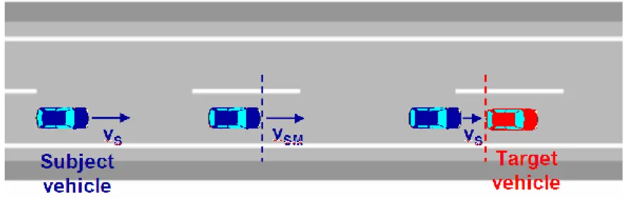
Max. initial speed
This is the maximum initial speed of the subject vehicle that does not result into a collision with a stationary or slower target vehicle.
The maximum initial speed of the subject vehicle is measured at a reference distance or initial distance from the target vehicle. The initial distance is specified in the testing protocol.
Figure 4: Maximum initial speed scheme
Generally, the subject vehicle is tested for its intervention capability to avoid collision with a stationary target vehicle. The safety indicator is the maximum initial speed that does not result into a collision with the target vehicle.
The safety criterion is: VSM Vmin where the minimum initial speed Vmin is specified in the
eVALUE 22 ICT-2007-215607
eVALUE-101115-WP2-D22-V20-FINAL.doc Max deceleration of the target vehicle
The max deceleration of the target vehicle is the maximal deceleration of the target vehicle which does not result into a collision.
Max deceleration of the subject vehicle (% of max braking capabilities of the vehicle)
The max deceleration of the subject vehicle is the maximal deceleration of the subject vehicle during the whole testing procedure.
Collision speed
Collision speed is the speed, at which the subject vehicle collides into the target vehicle. It is measured at the moment of the collision. A possibility to measure the collision speed is by means of a rabbit vehicle or a balloon vehicle. Therefore the measurement is damage free and repeatable.
The collision speed has major impact on the kinetic energy in case of a collision:
2
2
1
collision kinmv
E
Subject vehicle axEspecially when the system is not able to avoid the crash, it is important to know whether the deceleration provided was up to the full capabilities of the vehicle or limited by the system. That indicates until which conditions (speed and distances) the vehicle will be able to avoid a crash.
Warning to other users
This value represents the moment and how the system warns the other drivers that a potential accident situation has been detected and the vehicle is braking (or not). As for the warning signal, it may be analysed according to the time gap to time to collision.
Brake pedal force
If required by the system, this is used to know the level of input required to operate a deceleration. It shall be expressed in % of the brake pedal maximal force applicable (usually 650 N).
3.2.2.2 Suitable for cluster 2
(Also, some of the safety indicators shown above could be suitable).
Collision speed
See previous chapter. In this case, the collision would be against a fixed object on the roadside or a vehicle driving in the next lanes.
Time to collision
See previous chapter. In this case, the collision would be against a fixed object on the roadside or a vehicle driving in the next lanes.
Timing of warning signal / intervention
See previous chapter.
Standard deviation lane position
During the manoeuvre, the middle of the lane is considered as optimum and deviations from the optimum are measured each time step. Then, the standard deviation of these measures is calculated. It is one of the most common performance metrics. Its popularity is probably due to its high face validity and computational simplicity.
eVALUE 23 ICT-2007-215607
eVALUE-101115-WP2-D22-V20-FINAL.doc Time to cross line (TTCL)
This value represents the time remaining before crossing the line. The objective is to know how much time before (or after) crossing the line the system warns or acts. Maximal or mean values can be used as indicators.
It is calculated by: TTCL = lateral distance to lane / lateral speed (ground reference)
Peak lane deviation
The peak lane deviation is the maximum magnitude of lateral position as measured from a point on the centreline of the vehicle projected downward to the pavement and subtracted from lane centreline or other fixed reference.
Time exposed TTC (TET)
The Time exposed TTC is the sum of the time being exposed to lower TTC during a manoeuvre. It describes the exposition to safety-critical time-to-collision values over specified time duration. A single TTC value gives no information about exposure to risk above a certain level, while TET does.
Time integrated TTC (TIT)
The Time integrated TTC gives information of the risk exposure in terms of time and severity to a TTC below than a certain defined threshold. TET has one major drawback: it does not consider enough really small TTC during a short time. TIT tries to overcome this by calculating the integral of time spent below a TTC threshold. .
3.2.2.3 Suitable for cluster 3
Related to mu-split braking scenarios
Stopping distance
It is the distance travelled by the vehicle during the braking manoeuvre. It is a performance parameter, directly correlated to the risk of collision.
Maximum initial speed (for a specific braking distance)
Maximum initial speed is the highest speed at which the vehicle can be stopped within a specific braking distance
Use of adherence
A parameter able to quantify the control done by the vehicle‟s systems of the available adherence of the different wheels in mu-split scenario.
Driver steering input
It will analyse the steering wheel angle, speed, torque done by the driver in order to quantify the amount of driver activity.
Lateral deviation
It is the maximum lateral deviation reached during the braking manoeuvre. For a closed-loop braking, it is a control parameter useful to check the quality of the closed-loop. For an open-loop braking it is an indicator of the vehicle stability.
Yaw response
Yaw response is the rotation around the z axis of the vehicle. Yaw rotation is related to the control of the vehicle hence it is important for safety.
eVALUE 24 ICT-2007-215607
eVALUE-101115-WP2-D22-V20-FINAL.doc
Related to obstacle avoidance scenario
(Also, some of the safety indicators shown above could be suitable).
Lateral displacement
It is the value of the lateral displacement when the dwell manoeuvre starts (1.07 s). It is the responsiveness parameter suggested by FMVSS 126.
Maximum initial speed
Maximum initial speed is the highest speed at intervention at which the vehicle can manage the avoidance scenario.
Yaw rate ratios
They are the ratios between the yaw rate at certain times after the end of the steering wheel actuation and the yaw rate peak. They are the stability parameters suggested by FMVSS 126.
Driver intention following
This parameter represents the performance of a vehicle in terms of how closely it responds to the driver input. In an avoidance manoeuvre, the first half of the Dwell sine can be
analysed and a prediction can be made about how the vehicle should respond in the second half. By comparing predicted response with actual response, effectiveness can be assessed in terms of response control and stability.
Vehicle speed variation
It is the difference in velocity between the start and the end of the manoeuvre. Together with sideslip angles peaks, it gives an idea about how much the ESC has to work in order to keep the vehicle stable.
Sideslip angle peaks
They are the minimum and maximum values of sideslip angles during a manoeuvre. They are stability parameters directly related to the oversteer tendency of the vehicle.
Related to fast driving into a curve scenario
(Also, some of the safety indicators shown above could be suitable).
Lateral deviation
Lateral position deviation respect to the closing curve reference.
Maximum initial speed (for a specific curve scenario)
Maximum initial speed is the highest speed at the entrance of the curve at which the vehicle can manage the curve scenario.
Related to rollover scenario
(Also, some of the safety indicators shown above could be suitable).
Two wheel lift
This is represents the rollover condition: if both inner wheels lifted more than 2 inches from the ground and for more than 20 ms.
Roll rotation
Roll rotation is the rotation around the x axis of the vehicle. Roll rotation is related to the stability of the vehicle and hence important for safety.
eVALUE 25 ICT-2007-215607
eVALUE-101115-WP2-D22-V20-FINAL.doc
3.3 Instrumentation of the vehicles
This chapter describes the instrumentation to be used during the tests. It is described in a general sense, not differentiating among cluster 1, 2 or 3. Not all the instrumentation is required for all the tests developed within eVALUE. The devices are described according to the capabilities of the most commonly used ones. For this reason, all the instruments are represented by an example. The use of these instruments should not be understood as requirement, as other solutions with similar capabilities could be found. Some of the devices shown in this chapter may be used within eVALUE.
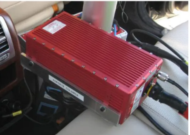
Positioning system
Example of equipment: Oxford Technical Solutions - OXTS RT 3002
The positioning system should include an inertial platform combined with a high accuracy GPS Navigation System. The objective of this combination is providing a high accuracy in the positioning of the vehicle, in order to calculate relative distances and closing speeds to other vehicles or objects. The use of the inertial platform should also provide highly accurate linear accelerations and angular velocities, which allow the calculation of parameters related to the dynamics of the vehicle. The system should be able to record the data of the test, with the suitable rate and filter it.
In a particular case, the OXTS RT 3002 is an advanced six-axis inertial navigation system that incorporates an L1/L2 RTK GPS receiver and delivers better than 0.02m RMS positioning under dynamic conditions using differential corrections. The outputs from the RT3002 Inertial and GPS Navigation System are derived from the measurements of the accelerometers and gyros. Using the inertial sensors for the main outputs gives the RT3002 system a fast update rate (100Hz) and a wide bandwidth. All the outputs are computed in real-time with a very low latency.
Figure 5: Installed positioning system – OXTS RT3002
Communications system
Example of equipment: Oxford Technical Solutions - OXTS RT Range
For tests where more than one vehicle takes part, it would be need to have a communications system able to exchange data between the positioning platform of all the vehicles, in real time, with the objective of synchronizing the registered data and the response actions.
In this particular case, the OXTS RT-Range is used for two functions: accurate (2 cm) measurement of the relative motion between two vehicles and synchronization. All measurements are online, in real-time and output on a CAN bus, including the Target vehicle measurements being relayed to the Subject vehicle's CAN bus.
eVALUE 26 ICT-2007-215607
eVALUE-101115-WP2-D22-V20-FINAL.doc
Figure 6: communication system – OXTS RT Range
X longitudinal y lateral Host Vehicle Target Vehicle Origin point Θxy (Dx,Dy)
Figure 7: Coordinates system
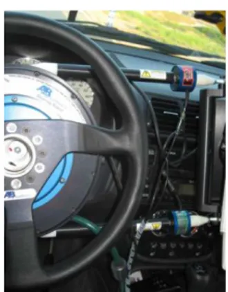
Steering Robot System
Example of equipment: Anthony Best Dynamics - ABD SR60
The maneuvers implemented over the steering system of the vehicle need to be implemented in an accurate way, in order to provide consistent data. For this reason, the use of steering robots is recommended.
This will provide the repeatability required for implementing the tests and evaluating the results, but some issues related to the inclusion of a real driver (driver in the loop) might be limited. This problem is further discussed in the specification of the test procedures.
In a particular case, the ABD SR60 Steering Robot or the Programmable Steering Controller is designed to apply inputs to a vehicle‟s steering system through a closed loop control. The SR60 steering robot uses a direct drive brushed DC motor to produce over 60 Nm of torque. Torques of over 200 Nm might be needed for heavy vehicles. Typical maximum rates reach 2500 º/s.
eVALUE 27 ICT-2007-215607
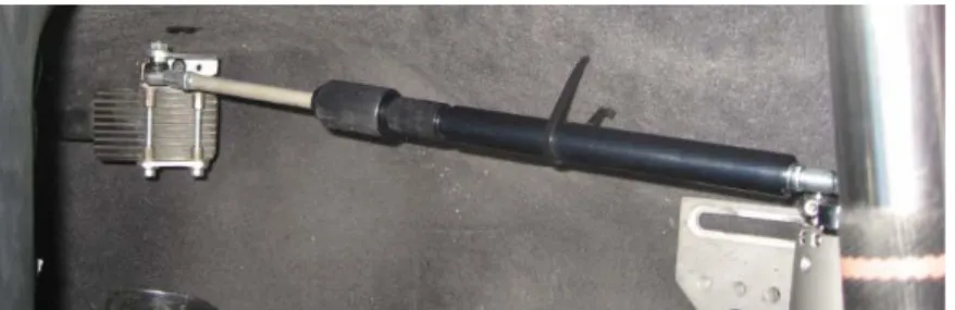
eVALUE-101115-WP2-D22-V20-FINAL.doc Braking Robot System
Example of equipment: Anthony Best Dynamics – ABD BR1000
The same comments done for the steering robot may apply for a braking pedal robot.
In a particular case, the ABD Brake Robot is designed to apply inputs to a vehicle's brake pedal for braking characterization and handling behavior measurement. It is typically used to apply step or ramped force or position inputs to the brake pedal. The ABD BR1000 can apply forces of 1400N to the brake pedal at a maximum velocity of 600mm/s.
Figure 9: Braking robot installed in vehicle
Accelerator Robot System
Example of equipment: Anthony Best Dynamics – ABD AR series
The same comments done for the braking robot may apply for an accelerator pedal robot. The AR series Accelerator Pedal Robot is designed to apply inputs to a vehicle‟s throttle pedal for closed loop vehicle speed control.
Figure 10: Accelerator robot installed in vehicle
Driving robot capabilities
The driving robot is able to save and reproduce any manoeuvre made by a driver by saving the path. It is also possible to create specific path according to the test requirements as lane change, slalom, braking manoeuvre, accelerating manoeuvres. Using the driving robot with RT 3002 allows reaching a less than 2 cm path following precision.
Optical Speed / Slip Angle Sensor
eVALUE 28 ICT-2007-215607
eVALUE-101115-WP2-D22-V20-FINAL.doc
Figure 11: Optical Speed / Slip Angle Sensor
3.4 Specifications for Physical Tests of cluster 1 3.4.1 Introduction
In WP1, a total of three scenarios were selected in order to validate the vehicle from a longitudinal point of view. These scenarios represent a hazard in front of the vehicle when driving on a straight road, on a curve and when an object (vehicle, pedestrian…) crosses the road. For these 3 scenarios, different test procedures have been developed in D2.2.
Taking into account the safety functions suitable for the accident scenarios of cluster 1 and cluster 2, a general situation can be identified. A vehicle driving in a stabilized condition and having a sudden hazard (vehicle in front braking, object crossing, lane departure…). The systems fitted in this vehicle should be able to detect the situation, warn the driver and actuate to avoid the accident and minimize the consequences.
These situations can be represented with the following diagram:
t0 t1 t2 t3 t4 pre-stabilitzation period, driving at the same speed no warning /
no intervention no interventionwarning / interventionwarning /
t5
full intervention
RUPTURE POINT OF NO RETURN
!
t6 post crash actions CRASH t5' NO CRASH stabilization timeFigure 12: Timeline for cluster 1 and 2 analyses
3.4.2 Aims and goals with physical testing in cluster 1
The objective of the test procedures developed in cluster 1 should be able to represent the accident scenarios defined in WP1 and implement them in a way that it is possible to apply the timeline proposed in the previous chapter and identify the safety indicators proposed. The safety functions studied in cluster 1 have two levels of operation, warning and intervention. These two levels should also be analysed within the test procedures proposed.
eVALUE 29 ICT-2007-215607
eVALUE-101115-WP2-D22-V20-FINAL.doc
3.4.3 Test Procedures for Physical Tests of cluster 1
3.4.3.1 Test Procedure C1-1&2#1 Deceleration of target vehicle
3.4.3.1.1 Test Procedure description
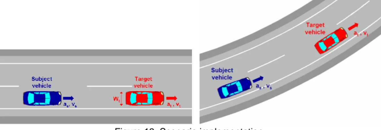
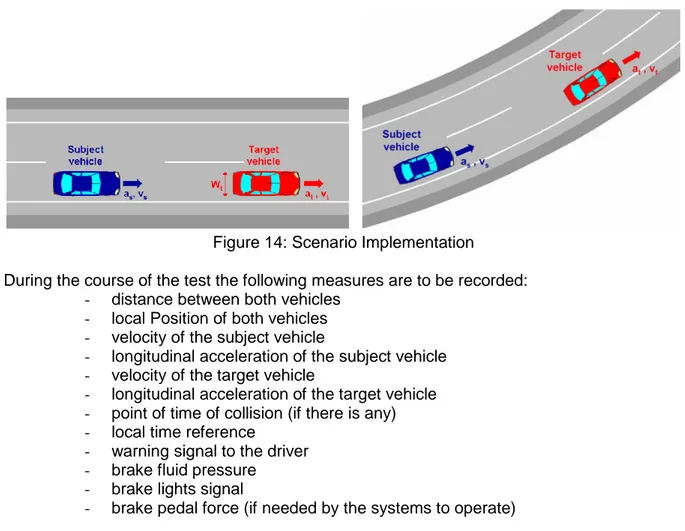
Scenario:
C1-1 and C1-2: Straight road / curved road
It represents a rear end collision with decelerating target vehicle.
Environment:
The test is to be conducted on a flat dry surface with a horizontal visibility more than 1 km. The temperature shall be above 5°C. The environmental conditions shall not change during the course of the test.
Road parameters:
The friction coefficient of the road surface shall not differ from standard road types.
Road layout:
The test is to be performed on a straight track and on a curved track with a defined curve radius.
Subject vehicle:
The subject vehicle is to be equipped with measurement tools in order to record the necessary measures and to warranty the precision and repetitiveness requirements of the test.
Target vehicle:
The target vehicle is simulated by a dummy vehicle that is representative to an ordinary vehicle so that vehicle systems are able to detect them, but possible to crash into.
The target vehicle shall be varied between: - passenger vehicle
- motorcycle - truck
The target vehicles have to be in a clean condition. The vehicles shall not be changed during the course of the test.
The target vehicle is to be equipped with measurement tools in order to record the necessary measures.
Initial conditions:
The initial velocity of the subject vehicle and the target vehicle shall be varied between 30 and 90 km/h.
The time gap between the both vehicles should be between 0.5 and 3 s. The deceleration of the target vehicle shall be between 0.1 and 0.7g.