SKI Report 01:35
Examination of Stress Corrosion Crack Tip
Microstructures in Stainless Steel
Simon Dumbill
September 2001
ISSN 1104-1374 ISRN SKI-R-01/35-SE
SKI Perspective
Background
Stress corrosion cracking is one of the most serious materials related problems
encountered in Boiling Water Reactors. The crack propagation rate has been shown to be strongly affected by sulphates in the coolant. Typical concentrations of sulphates and other anions in the primary water are of the order of 1 ppb. The values can
increase temporarily to much higher values during chemical transients. Shorter periods of such exposure give no effect in the laboratory, but there seems to be an integrated threshold value (memory effect) beyond which the propagation rate increases rapidly, as reported by Per Lidar in earlier work sponsored by SKI and the Swedish utilities (14.4/931463;92430. However at that time no plausible explanation for the results was forwarded.
Since this can be an important factor in the application of the regulations governing the integrity of structural components (SKIFS 2000:2, previously 1994:1), SKI commissioned Studsvik Material AB (now Studsvik Nuclear AB) to develop an hypothesis for the observed effects (14.4/960399;96082). Following this SKI commissioned AEA Technology to perform metallographic and analytical work on one of the specimens exposed in the experimental programme (14.4/960399;97129). The results of those studies, although not conclusive, supported the hypothesis
proposed by Hermansson. This work was presented at the Environmental Degradation conference held on Amelia Island in 1997, and also included in an SKI report (97:35). Sulphate entering the crack environment can be reduced down to sulphide.
Intermediates like polysulphides (disulphide and others) and also thiosulphate might be formed. Intermediates and sulphates themselves can form deposits together with metal ions formed in the anode process. Deposits are believed to alter the oxide in the cathodic areas and to contribute to the permeability of this oxide as well as to the growth and extension of the cathodic area. The acid function of hydrogen sulphate could also neutralise hydroxide ions formed in the cathodic process.
SKI:s goals for the project
In the previous analysis work performed by AEA Technology only the fractured surfaces of the specimen could be examined. Recent advances in preparation
techniques have enabled detailed study of the crack tips of stress corrosion cracks, and AEA have proven their capability in this area. The work reported here was aimed at furthering the analysis work concerning support of Hermansson's hypothesis by examining the crack tip of the stainless steel specimen tested in simulated BWR water with sulphate additions. A range of electron optical techniques was used.
SKI has previously supported similar work at Pacific Northwest National Laboratory (14.41-980893;98198) regarding internal oxidation of seam generator tubes. SKI considers it vital that specimen preparation techniques which are at the forefront of development are used by more than one research team in order to eliminate the
possible criticism that observations can be caused by the technique rather than the mechanism to be studied. Demonstration of the more general viability of this technique was a secondary motive for this work.
Results
Despite the age of the specimen sulphur was found to be incorporated into the spinel on the crack wall. It was also present as nickel sulphide precipitates within the crack. Sulphur was also found ahead of the crack tip and in a precipitate some 60 nm ahead of the visible crack tip in a precipitate on an otherwise precipitate-free grain boundary. All these observations further support the hypothesis to explain the aggressiveness of the sulphate species in stress corrosion cracking.
SKI considers that the results in this report constitute and important demonstration of a relatively new analysis tool which can be used to help to explain cracking problems in the nuclear industry.
SKI has no immediate plans to continue this work directly. Project information
SKI:s project manager: Karen Gott Project number: 00173
Other SKI reports and publications from related SKI projects:
Per Lidar, Influence of sulfate transients on crack growth rate of sensitized stainless steel in
water at 288 oC. Proceedings of the Seventh International Symposium "Environmental
Degradation of Materials in Nuclear Power Systems - Water Reactors", Breckenridge, CO in August 1995
Mechanism for the effect of Sulphate on SCC in BWRs SKI report (97:35).
S. M. Bruemmer, V. Y, Gertsman & L. E Thomas Corrosion. High resolution
comparison of primary- and secondary-side intergranular degradation in Alloy 600 steam generator tubing. NACE Corrosion 2000, Paper 196, Orlando, FL. March
2000.-SKI Report 01:35
Examination of Stress Corrosion Crack Tip
Microstructures in Stainless Steel
Simon Dumbill
AEA Technology Nuclear Science
B7, Windscale
Seascale
Cumbria CA20 1PF
United Kingdom
September 2001
This report concerns a study which has been conducted for the Swedish Nuclear Power Inspectorate (SKI). The conclusions and viewpoints presented in the report are those of the author/authors and do not
Contents
Summary ... 1 Introduction ... 1 Experimental ... 2 Results ... 3 Discussion ... 5 Conclusions ... 6 Figures 2–13 ... 7–19 References ... 20SUMMARY
Intergranular Stress Corrosion Cracking (IGSCC) of austenitic stainless steel components is one of the major materials degradation processes in Boiling Water Reactors (BWRs) and its dependence on the plant water chemistry has been found to be an important factor. Of the contaminants found in BWR water, sulphate ions have been identified as the most aggressive species and their effect has been studied in previous SKI funded work (Lidar 1995, Hermansson et al 1997).
Sample preparation techniques developed recently allow the examination of stress corrosion microstructures with analysis on the nanometre scale. A sample has been prepared from material tested by Lidar (1995) and studied using advanced electron microscope techniques.
Compositional analyses of the crack-wall oxide indicated that it is (Fe,Cr)2O3 and that
this oxide incorporates up to 10at% sulphur and some nickel. However, much more sulphur is stored in a nickel sulphide phase that was found precipitated within the crack. The Fe:Cr ratio in the oxide does vary significantly from area to area.
In the crack tip region, the crack was found to be following a grain boundary free of carbide precipitates. A single grain boundary precipitate some 60nm ahead of the visible crack-tip was found and analysed. This precipitate was enriched in nickel and sulphur. Sulphur was also found within a few nanometres of the visible crack tip. The oxides in the crack-tip region were a mixture of Fe2O3 and (Fe,Cr)2O3 and incorporated nickel
metal particles up to 100nm in diameter.
INTRODUCTION
Intergranular Stress Corrosion Cracking (IGSCC) of austenitic stainless steel components is one of the major materials degradation processes in Boiling Water Reactors (BWRs) and its dependence on the plant water chemistry has been found to be an important factor. Of the contaminants found in BWR water, sulphate ions have been identified as the most aggressive species and their effect has been studied in previous SKI funded work (Lidar 1995, Hermansson et al 1997). Hermansson considered the electrochemistry of cracks in a sulphated water environment and listed six examples of likely reactions inside the crack:
• Anodic formation of Fe2+, Ni2+ at the crack tip • Hydrolysis of metal ions, e.g. Fe2+
• Formation of complexes between inwardly diffusing anions and outwardly
migrating metal ions, e.g. FeCln-(n-3)
• Precipitation of iron, nickel or chromium sulphates
• Reduction of sulphate to sulphide in a strongly reducing environment producing FeS2 or Ni2S3.
• Formation of H2S at the crack tip in an acidic environment.
Recent advances in electron microscopy techniques and also, importantly, in sample preparation techniques, have greatly increased the information which it is possible to obtain relevant to the study (and ultimately mitigation) of environmentally-assisted cracking (EAC). This work was initiated in order to apply these methods to the study of the material tested by Lidar and search for evidence of the processes suggested by Hermansson.
EXPERIMENTAL
Traditional methods of sample preparation for the transmission electron microscope (TEM), such as electropolishing, are effective only for homogeneous specimens. Indeed, it is frequently difficult to prepare samples which include certain types of second phase particles using this technique. The outcome of this difficulty is that information has generally been gathered only from materials in which the sample preparation is straightforward and this generally means that only non-failing locations are studied. Over the last four or five years, two types of ion-beam instrument have emerged which make possible on a routine basis the preparation of TEM samples from specific locations and inhomogeneous materials. These methods have opened up the possibilities for obtaining mechanistically relevant microstructural data in EAC studies. The chief methods that can produce TEM samples of oxide in place on its parent metal (whether on a free surface or within a crack) are low-angle ion-beam polishing and focused ion beam milling (FIB). The initial stages of sample preparation involve sectioning to remove a small volume of material containing the crack to be studied. In the case of low-angle ion-beam polishing, the section of material is impregnated with a low-viscosity resin and carefully ground until the material remaining in the vicinity of the crack is on the order of 10µm thick. The sample is then mounted in the ion-beam instrument and ‘polished’ with a (normally argon) ion beam of a few kV energy until it becomes thin enough for observation in the electron microscope. The progress of the thinning is carefully monitored by frequent interruption and inspection until the electron transparent region contains the crack-tip. Samples prepared in this way can be
sequentially re-polished and re-analysed to obtain analysis along the length of a crack. The sample quality is excellent and high-resolution imaging and analysis are possible.
Figure 1: Schematic of cross-section sample preparation route
A small section of the material of interest is mounted in a 3mm diameter annulus as shown in Figure 1. The disc is then ground to ~70µm thickness before dimpling. The dimpling stage produces a hemispherical dimple in the sample and is centred on the region of interest, for example on an oxide layer or a stress-corrosion crack, by careful positioning using an optical microscope. The dimple is polished using colloidal alumina paste to produce a smooth surface before ion-beam thinning.
Support
ring
As explained above, the final stages of preparation of the sample involved low-angle ion-beam thinning using argon gas and accelerating voltages of 2-5kV in a Gatan Precision Ion Polishing System (PIPS) interrupted frequently to monitor progress using the TEM.
Microscopy was carried out using a Vacuum Generators HB501 scanning transmission electron microscope equipped with an Oxford Instruments ISIS energy-dispersive X-ray (EDX) analysis system and a Gatan parallel electron energy-loss spectrometer. The microscope operates with a cold, field-emission electron gun which gives a high-brightness beam of ~1.5nm diameter.
The sample examined in this work was one of the samples tested by Lidar (1995) and supplied to Harwell for the analysis reported in Hermansson (1997). The material is Type 304 stainless steel which was solution treated at 1050°C for 20 minutes followed by a sensitising heat treatment of 680°C for one hour plus 24 hours at 500°C. This is expected to produce narrow chromium-depleted regions at the grain boundaries.
RESULTS
Figure 2 shows optical micrographs of the section of material selected for study. The extensive secondary cracking extends several grains away from the original crack plane. The first region studied (indicated in Figure 2a) was a branch off the main secondary crack and must have grown parallel to the stress axis within the CT sample. An electron micrograph of part of this crack is shown in Figure 3. The crack appears to have
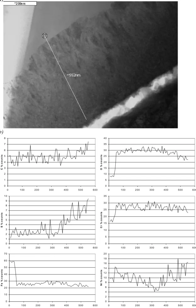
propagated along a grain boundary and changed direction at a triple point. The walls are heavily oxidised and Figure 4a shows the open crack and the oxidised crack-wall near the triple point. At this point the oxide is ~500nm thick and is duplex in structure with the oxide near the metal showing a columnar grain structure whereas the grain structure of the layer adjacent to the crack is equiaxed. The oxide here is rich in chromium and iron and compositionally is more like an iron-substituted chromium oxide, (Fe,Cr)2O3, than an iron chromite FeCr2O4 phase. Also shown in Figure 4b is a
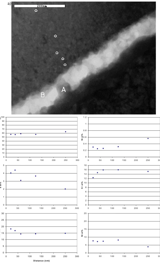
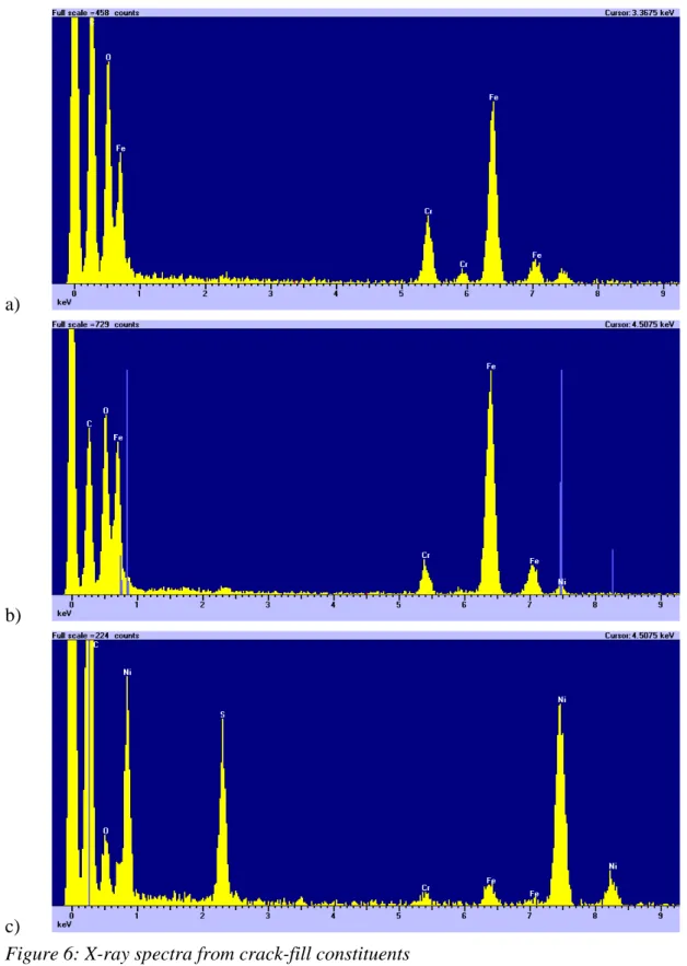
semi-quantitative compositional linescan across the oxide. The linescan starts in the steel before moving into the columnar-grained oxide. The point where the columnar structure ends and the equiaxed structure begins is also the point where the sulphur and nickel content of the oxide begins to increase. The results of quantitative analyses near the crack face are shown in Figure 5. The sulphur content of the oxide increases by a factor of ~2 in the 250nm from the centre of the oxide to the crack face. This image shows the crack is largely open but does contain some deposits. This crack-fill consisted of three components: (i) Fe,Cr-rich oxide (ii) an iron oxide [A] and (iii) a nickel
sulphide [B]. X-ray spectra from these three components are shown in Figure 6. Most notable of these is the nickel sulphide, though the composition (~Ni2S) suggests that this
is not the Ni2S3 phase suggested by Hermansson. Though this spectrum shows a small
oxygen peak, this is probably associated with traces of the oxide rather than belonging to the sulphide. Other spectra from this phase consistently show no oxygen content and also a constant composition.
Figure 7 shows an image of the boundary between the 304 steel and the crack-wall oxide together with the analysis locations. The compositional profile generated from this data is given in Figure 7b. The oxide in this location is of the columnar-grained type and has a very low sulphur content. An interesting observation is that nickel appears to be slightly enriched at the boundary between the metal and the oxide. This result is
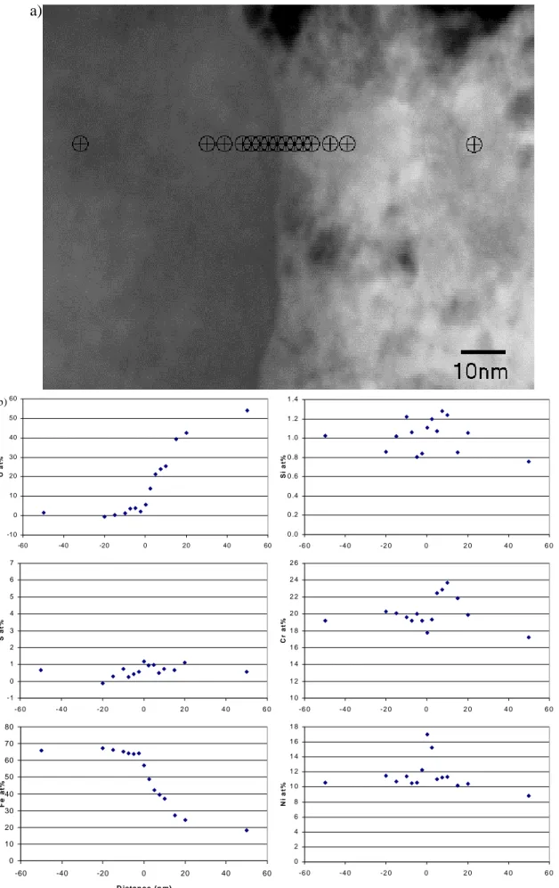
repeated in Figure 8 where a more detailed examination of an interface region was made. In this case, the boundary between the metal and the oxide was accurately aligned parallel to the electron beam. At this boundary, nickel was found to be sharply
segregated. The profiles for iron and oxygen, however, exhibit a transition zone about 20nm wide in which the concentration gradually changes. The chromium concentration profile also exhibits a boundary region, though in this case, the concentration is raised compared to both the metal and the oxide.
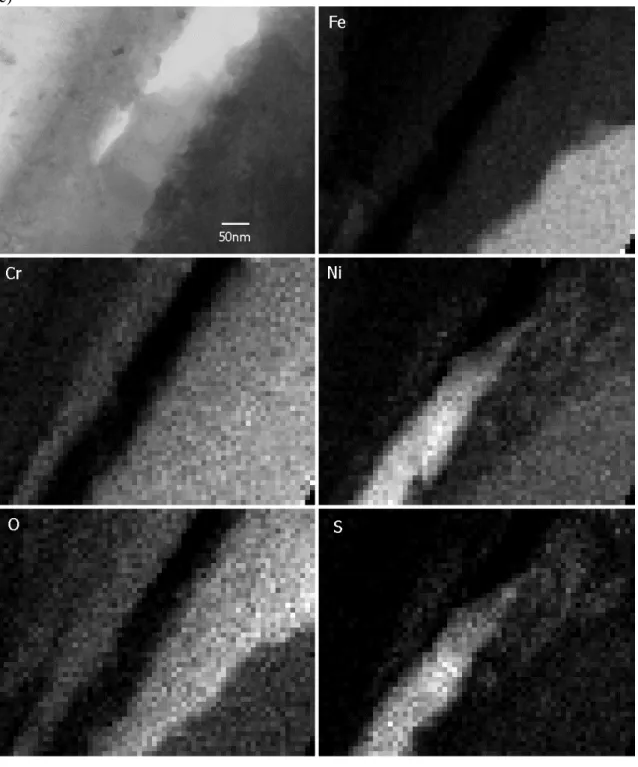
An image covering the whole width of the crack is shown in Figure 9a with the metal at the top left and bottom right-hand corners of the image. The linescan shown in Figure 9b begins in the oxide on the left-hand side of the crack, crosses a central region which contains precipitated nickel sulphide and corrosion debris, then crosses oxide on the right-hand side of the crack before passing in to the metal. The carbon profile shows that the crack is tightly filled with corrosion product at this location (compared to the top of the image where the crack is quite open). The oxygen profile shows that there is little or no oxygen associated with the central region of the crack, or in the metal as expected. Sulphur is found only in the central part of the crack and its distribution is closely mirrored by that of nickel. Chromium is enriched in the crack-wall oxide by almost a factor of two compared to the metal and the reverse is true for iron. X-ray maps from this region are shown in Figure 9c and clearly show the nickel sulphide
precipitation within the crack.
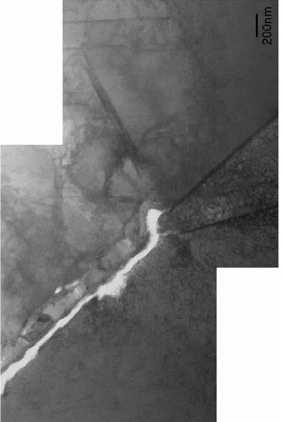
Further thinning revealed the crack-tip indicated earlier in Figure 2. The crack-tip is shown in Figure 10 and is clearly propagating along a grain boundary. The crack walls are heavily oxidised to a thickness of around 200nm and it appears that the crack is quite open right to the tip of the crack (though it must be recognised that this crack opening could have resulted from mechanical damage to the sample during preparation and handling). Interestingly, no chromium carbides or any other type of precipitation was found on this grain boundary (the visible part of this boundary extended ~5µm ahead of the crack tip). X-ray maps illustrating the distribution of elements are shown in Figure 11 and are very helpful in interpreting the microstructure of this crack tip. The open crack is lined with a layer of (Fe,Cr)2O3 on top of Fe2O3. These oxides contain
particles of nickel ranging in size from 10nm to 100nm. This is represented
schematically in Figure 12. Occasionally, sulphur is associated with the nickel, even to the very end of the crack.
The tip of the intergranular crack is shown at high magnification in Figure 13a. This image shows that the crack tip is quite blunt, though at only ~20nm wide it is only a tenth of the crack width shown in Figure 11. This crack tip can be seen in Figure 11 and may represent a re-initiation of crack growth. The EDX compositional profiles shown in Figure 13b start with a profile just 5nm behind the crack tip which shows a small carbon peak near the centreline (probably an artefact due to the resin used in the sample
preparation); oxygen and sulphur are enriched and must be related to the corrosion process at the crack tip; chromium is depressed and nickel enriched at the grain
boundary which is typical for a grain boundary in sensitised stainless steel. Further back from the crack tip, the oxides that are present are rich in chromium and poor in nickel compared to the steel matrix, so it appears that this profile shows that the oxidation of the steel proceeds initially via an ingress of oxygen rather than by outward diffusion of the metal ions. It is also very interesting that sulphur is identified within 5nm of the crack front.
The second profile is from 30nm ahead of the crack tip. The distribution of elements at this location is perfectly normal for a grain boundary in sensitised stainless steel and quantitative analysis showed the grain boundary composition to be Fe-11.4Cr-25.2Ni (wt%) compared to matrix levels of Fe-18.8Cr-11.6Ni at a distance of 45nm from the grain boundary.
The third profile crosses a 30nm precipitate on the grain boundary 60nm ahead of the crack tip. The precipitate is rich in sulphur and possibly chromium. The presence of sulphur in the precipitate is intriguing since sulphides are rare in stainless steels and, though the nearby crack tip is a possible source, the precipitate was not obviously connected by porosity to the crack tip.
The final profile was acquired from a location ~150nm from the crack tip and shows chromium depletion and nickel enrichment similar to the second profile.
DISCUSSION
Cross-section TEM sample preparation techniques have been applied to a laboratory compact tension sample. Regions containing secondary cracking were studied using high spatial resolution analysis techniques. Examination of the crack-wall oxide showed a change of structure in the oxide which correlated with the presence of sulphur and the much greater concentration of sulphur in the nickel sulphide phase that is present in the centre of the crack. The relative proportions of the transition metals in the oxide are quite constant: the ratio of Fe:Cr:Ni is 1:1:0.3 throughout the thickness of the crack-wall except close to the metal/oxide interface, as shown in Figure 8, where nickel is
enriched.
The separation of nickel from the other corrosion products is further illustrated in Figure 11 where nickel metal islands and more areas rich in nickel and sulphur are seen. The presence of nickel metal particles parallels the findings of Thomas (Thomas and Bruemmer 2000) in the study of Alloy 600. In that work the presence of Cr2O3 in the
main crack was also highlighted and distinct from the presence of both NiO and Cr2O3
in the ‘degraded’ grain boundaries which intersected the main crack. Of course, there is a great difference in the nickel concentration in Alloy 600 compared to 304, which makes the presence of nickel metal in the present case all the more remarkable.
The cracking studied in this work was far removed from the main propagating crack in the original CT testpiece and, judging from the width of the corroded region shown in Figure 10, may not have been actively propagating. However, several interesting findings can be identified. First, as already mentioned, the oxide present on the crack walls was found to contain sulphur. There was also a considerable quantity of sulphur deposited in the crack as a form of nickel sulphide, though probably not the Ni2S3
phase. It is likely that this storage of sulphur in the crack-fill oxides accounts for the long duration of the periods of accelerated crack growth after a sulphate transient during the SCC testing. Secondly, evidence that implicates sulphur in the SCC process was found at the crack-tip where sulphur was detected within a few nanometres of the tip and in the precipitate ahead of the visible crack-tip shown in Figure 13. This is similar to the findings reported by Scott (1999) of perhaps the only published analyses of stress-corrosion microstructures in stainless steel which noted, as in the present case, that solution impurities penetrated practically to the crack-tip.
Conclusions
A cross-section sample for high spatial resolution analytical electron microscopy has successfully been prepared from a section of an SCC-tested, sensitised Type 304 steel. Two areas of the sample were examined: a section of the crack-wall in a region where the cracking is ~500nm wide and the crack-tip region.
Compositional analyses of the crack-wall oxide indicated that it is (Fe,Cr)2O3 and that
this oxide incorporates up to 10at% sulphur and some nickel. However, much more sulphur is stored in a nickel sulphide phase that was found precipitated within the crack. The Fe:Cr ratio in the oxide does vary significantly from area to area.
In the crack tip region, the crack was found to be following a grain boundary free of carbide precipitates. A single grain boundary precipitate some 60nm ahead of the visible crack-tip was found and analysed. This precipitate was enriched in nickel and sulphur. Sulphur was also found within a few nanometres of the visible crack tip. The oxides in the crack-tip region were a mixture of Fe2O3 and (Fe,Cr)2O3 and incorporated nickel
Figure 2: Optical micrographs of prepared electron microscopy sample showing regions selected for analysis. a) Tertiary crack ~300µm from primary crack b) Crack tip.
Figure 3: Montage of electron micrographs showing analysis region 1. Crack walls are heavily oxidised and crack still is quite open.
a) b) 0 1 2 3 4 5 6 7 8 0 1 0 0 2 0 0 3 0 0 4 0 0 5 0 0 6 0 0 C % c oun ts 0 5 1 0 1 5 2 0 2 5 3 0 3 5 4 0 0 1 0 0 2 0 0 3 0 0 4 0 0 5 0 0 6 0 0 O % c ount s 0 1 2 3 4 5 6 7 8 9 1 0 0 1 0 0 2 0 0 3 0 0 4 0 0 5 0 0 6 0 0 S % c o unt s 0 5 1 0 1 5 2 0 2 5 3 0 3 5 0 1 0 0 2 0 0 3 0 0 4 0 0 5 0 0 6 0 0 C r % c o unt s 0 1 0 2 0 3 0 4 0 5 0 6 0 7 0 0 1 0 0 2 0 0 3 0 0 4 0 0 5 0 0 6 0 0 Fe % c ount s 0 2 4 6 8 1 0 1 2 1 4 1 6 1 8 2 0 0 1 0 0 2 0 0 3 0 0 4 0 0 5 0 0 6 0 0 N i % c o u n ts
Figure 4: a) Crack wall oxide showing columnar and equiaxed layers b) semi-quantitative compositional profile along indicated line (distances in nanometres).
a) 0 10 20 30 40 50 60 70 80 90 100 0 50 100 150 200 250 300 O a t% b) 0 0 .2 0 .4 0 .6 0 .8 1 1 .2 0 5 0 1 0 0 1 5 0 2 0 0 2 5 0 3 0 0 S i a t% 0 1 2 3 4 5 0 5 0 1 0 0 1 5 0 2 0 0 2 5 0 3 0 0 S at % 0 2 4 6 8 1 0 1 2 1 4 1 6 1 8 0 5 0 1 0 0 1 5 0 2 0 0 2 5 0 3 0 0 C r at % 0 5 10 15 20 25 30 0 50 100 150 200 250 300 D istan ce (n m) F e a t% 0 5 1 0 1 5 2 0 2 5 0 5 0 1 0 0 1 5 0 2 0 0 2 5 0 3 0 0 N i a t%
Figure 5: a) Crack in oxide showing analysis positions in crack-fill and crack-wall b) Analysis of crack-wall oxide as a function of distance from crack face
a)
b)
c)
Figure 6: X-ray spectra from crack-fill constituents a) Fe,Cr-rich oxide
b) Iron oxide (A in Figure 5) c) Nickel sulphide (B in Figure 5)
a 0 10 20 30 40 50 60 0 100 200 300 400 500 O a t% b) 0 .0 0 .2 0 .4 0 .6 0 .8 1 .0 1 .2 1 .4 0 2 4 6 8 1 0 1 2 S i a t% -1 0 1 2 3 4 5 6 7 0 1 0 0 2 0 0 3 0 0 4 0 0 5 0 0 S at % 1 0 1 2 1 4 1 6 1 8 2 0 2 2 2 4 2 6 2 8 0 1 0 0 2 0 0 3 0 0 4 0 0 5 0 0 C r at % 0 10 20 30 40 50 60 70 80 0 100 200 300 400 500 D istan ce (n m) F e a t% 0 2 4 6 8 1 0 1 2 1 4 0 1 0 0 2 0 0 3 0 0 4 0 0 5 0 0 N i a t%
Figure 7: a) Image of metal-oxide boundary b) Compositional analysis across the interface
a) -10 0 10 20 30 40 50 60 -60 -40 -20 0 20 40 60 O a t% b) 0 .0 0 .2 0 .4 0 .6 0 .8 1 .0 1 .2 1 .4 -6 0 -4 0 -2 0 0 2 0 4 0 6 0 S i a t% -1 0 1 2 3 4 5 6 7 -6 0 -4 0 -2 0 0 2 0 4 0 6 0 S at % 1 0 1 2 1 4 1 6 1 8 2 0 2 2 2 4 2 6 -6 0 -4 0 -2 0 0 2 0 4 0 6 0 C r at % 0 10 20 30 40 50 60 70 80 -60 -40 -20 0 20 40 60 D istan ce (n m) F e a t% 0 2 4 6 8 1 0 1 2 1 4 1 6 1 8 -6 0 -4 0 -2 0 0 2 0 4 0 6 0 N i a t%
Figure 8: a) High magnification image of metal/oxide boundary b) Compositional analyses across the interface
a) b) 0 0 .5 1 1 .5 2 2 .5 3 3 .5 0 2 0 0 4 0 0 6 0 0 8 0 0 1 0 0 0 C % c oun ts 0 5 1 0 1 5 2 0 2 5 3 0 0 2 0 0 4 0 0 6 0 0 8 0 0 1 0 0 0 O % c ount s 0 5 1 0 1 5 2 0 2 5 3 0 3 5 0 2 0 0 4 0 0 6 0 0 8 0 0 1 0 0 0 S % c o unt s 0 5 1 0 1 5 2 0 2 5 3 0 3 5 4 0 4 5 0 2 0 0 4 0 0 6 0 0 8 0 0 1 0 0 0 C r % c o unt s 0 1 0 2 0 3 0 4 0 5 0 6 0 7 0 8 0 0 2 0 0 4 0 0 6 0 0 8 0 0 1 0 0 0 Fe % c ount s 0 1 0 2 0 3 0 4 0 5 0 6 0 7 0 0 2 0 0 4 0 0 6 0 0 8 0 0 1 0 0 0 N i % c o u n ts
c)
Figure 9: a) Image of crack showing oxidised walls and central crack with deposits b) compositional linescan along indicated line c) X-ray maps illustrating the distribution of elements in this area.
16
Figure 10: Montage of ele
ctron micrographs
Figure 11: X-ray maps showing distribution of elements near crack tip Oxygen
Chromium Sulphur
a) b) 0 1 2 3 4 5 6 -80 -60 -40 -20 0 20 40 60 80 C % c ount s -4 -2 0 2 4 6 8 10 -80 -60 -40 -20 0 20 40 60 80 O % c ount s -2 0 2 4 6 8 10 12 -80 -60 -40 -20 0 20 40 60 80 S % co u n ts 0 5 10 15 20 25 30 -80 -60 -40 -20 0 20 40 60 80 Cr % c ount s 0 10 20 30 40 50 60 70 80 -80 -60 -40 -20 0 20 40 60 80 Fe % c o u n ts 0 5 10 15 20 25 30 -80 -60 -40 -20 0 20 40 60 80 Ni % c ount s
Figure 13: a) Crack tip and location of linescans b) semi-quantitative linescan analyses across crack tip and material ahead of crack.
REFERENCES
Lidar, P., Influence of sulphate transients on crack growth in type 304 stainless steel in
water at 288°C, Proc. Seventh Int. Symp. On Environmental Degradation of Materials
in Nuclear Power Systems – Water reactors, Breckenridge, Colorado, August 1995, p. 597-608. NACE International, Houston, Texas (1995).
Hermansson, H.-P., Gott, K., Vatter, I.A., Crossley, A. and Cattle, G., Mechanism for
the Effect of Sulphate on SCC in BWRs, SKI Report SKI-R—97/35 (1997).
Thomas, L.E. and Bruemmer, S.M. High-Resolution Characterization of Intergranular
Attack and Stress Corrosion Cracking of Alloy 600 in High-Temperature Primary Water Corrosion 56 (2000) 572-587.
Scott, P.M., An Overview of Internal Oxidation as a Possible Explanation of
Intergranular Stress Corrosion Cracking of Alloy 600 in PWRs, Proc. Ninth Int. Symp.
On Environmental Degradation of Materials in Nuclear Power Systems – Water reactors, Newport Beach, California, August 1999, p. 3-11. TMS, Warrendale, Pennsylvania (1999).