ACTA UNIVERSITATIS
UPSALIENSIS
Digital Comprehensive Summaries of Uppsala Dissertations
from the Faculty of Science and Technology
1644
Magnetization Dynamics in
Ferromagnetic Thin Films
Evaluation of Different Contributions to Damping in
Co
2
FeAl and FeCo Film Structures
SERKAN AKANSEL
ISSN 1651-6214 ISBN 978-91-513-0268-3
Dissertation presented at Uppsala University to be publicly examined in Polhemssalen, Ångströmlaboratoriet, Lägerhyddsvägen 1, Uppsala, Thursday, 3 May 2018 at 13:15 for the degree of Doctor of Philosophy. The examination will be conducted in English. Faculty examiner: Professor Erik Wahlström (Norwegian University of Science and Technology, Department of Physics).
Abstract
Akansel, S. 2018. Magnetization Dynamics in Ferromagnetic Thin Films. Evaluation of Different Contributions to Damping in Co2FeAl and FeCo Film Structures. Digital
Comprehensive Summaries of Uppsala Dissertations from the Faculty of Science and Technology 1644. 74 pp. Uppsala: Acta Universitatis Upsaliensis. ISBN 978-91-513-0268-3.
Static and dynamic magnetic properties of Co2FeAl and Fe65Co35 alloys have been investigated.
Co2FeAl films were deposited at different temperatures and the deposition parameters were
optimized with respect to structural and magnetic properties. As a result, a film with B2
crystalline phase was obtained without any post-annealing process. A lowest magnetic damping parameter of was obtained for the film deposited at 573K. This obtained low value is comparable to the lowest values reported in research literature. After optimizing the deposition parameters of this alloy, different seed layers and capping layers were added adjacent to the Co2FeAl layer
and the effect of these layers on the magnetic relaxation was investigated. In addition to adding nonmagnetic layers to Co2FeAl, the dependence of the magnetic damping parameter with respect
to the thickness of Co2FeAl was investigated by depositing films with different thicknesses.
A temperature dependent study of the magnetic damping parameter was also performed and the measured damping parameters were compared with theoretically calculated intrinsic Gilbert damping parameters. Different extrinsic contributions to the magnetic damping, such as two magnon scattering, spin pumping, eddy-current damping and radiative damping, were identified and subtracted from the experimentally obtained damping parameter. Hence, it was possible to obtain the intrinsic damping parameter, that is called the Gilbert damping parameter.
In the second part of the thesis, Fe65Co35 alloys were investigated in terms of static and
dynamic magnetic properties. Fe65Co35 films were deposited without and with different seed
layers in order to first understand the effect of the seed layer on static magnetic properties of the films, such as the coercivity of the films. Then the films with seed layers yielding the lowest coercivity were investigated in terms of dynamic magnetic properties. Fe65Co35
films with different rhenium dopant concentrations and with ruthenium as the seed and capping layer were also investigated. The purpose of this study was to increase the damping parameter of the films and an increase of about ~230% was obtained by adding the dopant to the structure. This study was performed at different temperatures and after subtraction of the extrinsic contributions to the damping, the experimental values were compared with theoretically calculated values of the Gilbert damping parameter. During the thesis work, magnetic looper and superconducting quantum interference device magnetometers set-ups were used for static magnetic measurements and cavity, broadband in-plane and broadband out-of-plane ferromagnetic resonance set-ups were used for dynamic measurements.
Keywords: spintronics, Gilbert damping parameter, magnetization dynamics, ferromagnetic
resonance, Heusler alloys, magnetic thin films
Serkan Akansel, Department of Engineering Sciences, Solid State Physics, Box 534, Uppsala University, SE-751 21 Uppsala, Sweden.
© Serkan Akansel 2018 ISSN 1651-6214 ISBN 978-91-513-0268-3
Dünyada her şey için, medeniyet için, hayat için, başarı için en gerçek yol gösterici bilimdir. Bilimin dışında yol gösterici aramak gaflettir, cahilliktir, doğru yoldan sapmaktır.
For everything in this world, for civilization, for life, for success, the truest guide is science. To seek a guide other than science is a mark of heedlessness, ignorance, and aberration.
Mustafa Kemal Atatürk
List of Papers
This thesis is based on the following papers, which are referred to in the text by their Roman numerals.
I Husain, S., Akansel, S., Kumar, A., Svedlindh, P., Chaudhary, S. (2016) Growth of Co2FeAl Heusler alloy thin films on
Si(100) having very small Gilbert damping by Ion beam sput-tering. Scientific Reports , 6: 28692
II Husain, S., Barwal, V., Kumar, A., Behera, N., Akansel, S., Goyat, E., Svedlindh, P., Chaudhary, S. (2017) Static and dy-namic properties of Co2FeAl thin films: Effect of MgO and Ta
as capping layers. AIP Conference Proceedings, 1832: 080007 III Akansel, S., Kumar, A., Behera, N., Husain, S., Brucas, R.,
Chaudhary, S., Svedlindh, P. Thickness dependent enhancement of damping in Co2FeAl/β-Ta thin films (Submitted)
IV Kumar, A., Pan, F., Husain, S., Akansel, S., Brucas, R., Bergqvist, L., Chaudhary, S., Svedlindh, P., (2017) Tempera-ture-dependent Gilbert damping of Co2FeAl thin films with
dif-ferent degree of atomic order. Physical Review B, 96: 224425 V Akansel, S., Venugopal, V. A., Kumar, A., Gupta, R., Brucas,
R., George, S., Neagu, A., Tai, C-W., Gubbins, M. A., Anders-son, G., Svedlindh, P., Effect of seed layers on dynamic and static magnetic properties of Fe65Co35 thin films (Submitted)
VI Akansel, S., Kumar, A., Venugopal, V. A., Banerjee, R., Autieri, C., Brucas, R., Behera, N., Sortica, M. A., Primetzhofer, D., Basu, S., Gubbins, M. A., Sanyal, B., Svedlindh, P. Enhanched Gilbert damping in Re doped FeCo films. A combined experimental and theoretical study (Submitted)
Papers not included in the thesis
VII Husain, S., Kumar, A., Barwal., V., Behera, N., Akansel, S., Svedlindh, P., Chaudhary, S., (2018) Spin pumping in ion-beam sputtered Co2FeAl/Mo bilayers: Interfacial Gilbert damping.
Physical Review B, 97: 064420
VIII Kumar, A., Akansel, S., Stopfel, H., Fazlali, M., Åkerman, J., Brucas, R., Svedlindh, P. (2017) Spin transfer torque ferromagnetic resonance induced spin pumping in the Fe/Pd bilayer system. Physical Review B, 95: 064406
IX Husain, S., Kumar, A., Akansel, S., Svedlindh, P., Chaudhary, S. (2017) Anomalous Hall effect in ion-beam sputtered Co2FeAl full Heusler alloy thin films. Journal of Magnetism
and Magnetic Materials, 442: 288–294
X Wei, Y., Akansel, S., Thersleff, T., Harward, I., Brucas, R., Ranjbar, M., Jana, S., Lansaker, P., Pogoryelov, Y., Dumas, R. K., Leifer, K., Karis, O., Åkerman, J., Celinski, Z., Svedlindh, P. (2015) Exponentially decaying magnetic coupling in sputtered thin film FeNi/Cu/FeCo trilayers. Applied Physics
Contents
1.Introduction ... 11 2. Experimental Techniques ... 13 2.1. Structural Characterization ... 13 2.1.1. X-ray diffraction ... 13 2.1.2. X-ray reflectivity ... 15 2.2. Magnetic Characterization ... 15 2.2.1. Static Magnetization ... 16 2.2.2. Dynamic Magnetization ... 18 3.Magnetization Dynamics ... 24 3.1. Magnetic Damping ... 24 3.1.1. Gilbert Damping ... 243.1.2 Two Magnon Scattering ... 25
3.1.3. Eddy-Current Damping ... 26
3.1.4. Radiative Damping ... 27
3.1.5. Spin Pumping... 27
3.1.6 Mosaicity Contribution ... 27
3.1.7. Inhomogeneity Contribution ... 27
3.2. Equations for Analyzing Magnetization Dynamics ... 28
3.2.1. Cavity FMR Analysis ... 28
3.2.2. In-plane Broadband FMR analysis ... 29
3.2.3 Out-of-plane Broadband FMR analysis ... 29
3.2.4. Subtracting Some Extrinsic Relaxation Contributions in Out-of-plane Measurements ... 30
4. Dynamic Properties of Co2FeAl Thin Films ... 32
4.1. Material Properties ... 32
4.2. Analysis and Results ... 35
5. Dynamic Properties of Fe65Co35 Thin Films ... 53
5.1. Material Properties ... 53
6. Concluding Remarks ... 64 6.1. Summary ... 64 6.2. Outlook ... 65 7. Sammanfattning ... 66 Acknowledgments... 69 Bibliography ... 71
Abbreviations
CPW Coplanar waveguide FFT Fast fourrier transform FMR Ferromagnetic resonance
Landé g-factor
GIXRD Grazing incidence XRD GMR Giant magnetoresistance
Coercivity
Uniaxial anisotropy field Effective magnetic field Resonance field
HRTEM High resolution TEM LL Landau Lifshitz
LLG Landau Lifshitz Gilbert Effective magnetization
MRAM Magnetoresistive random access memory Saturation magnetization
MOKE Magneto-optic Kerr effect
MPMS Magnetic properties measurement system MTJ Magnetic tunnel junction
PMA Perpendicular magnetic anisotropy PPMS Physical properties measurement system RBS Rutherford backscattering
RT Room temperature
SQUID Superconducting quantum interference device TEM Transmission electron microscopy
TMS Two magnon scattering
VSM Vibrating sample magnetometer XRD X-ray diffraction
XRR X-ray reflectivity
Eddy-current contribution to damping
, Total damping parameter including both intrinsic and extrinsic contributions
, , Intrinsic Gilbert damping parameter which remains after extrinsic contributions are subtracted from total damping Radiative contribution to damping
Spin pumping contribution to damping
Full width half maximum of the FMR absorption lin-ewidth
1.Introduction
The word magnetism comes from a city called Manisa, which is today on the west coast of Turkey. The magnetic material magnetite was first found in this city by the ancient Greeks and this material was named after the Greek tribe “the Magnetes” who lived in the city Magnesia (Manisa), which be-longed to the Greeks at that time. The source of the inspiration for one of today’s the most important scientific fields “magnetism” is magnetite. Most of the technological devices that we use today in our daily life are based on magnetism and magnetic materials. The word dynamics comes from the Greek word “dynamikos” which means “powerful”. However, in physics it refers to properties of a system which change over time. The research field magnetization dynamics is based on the change of magnetic properties of materials over a period of time and this change is mostly dependent on the applied external magnetic field. Magnetization deals mostly with the dynam-ic properties of a quantum property of the electrons called “spin”, whdynam-ich refers to the field known as spin dynamics. Spintronics is a relatively new aspect of technology which developed from spin dynamics.
Conventional electronics technology was based on the charge of elec-trons. However, spintronics integrates the spin properties of the electrons into electronics technology. Spin can basically be explained as the quantum mechanical angular momentum which is hard to understand through classical physical properties. Instead of using the charge of electrons in daily applica-tions, replacing charge by spin and understanding and tailoring dynamic properties of the electron spins will lead to production of novel devices that work faster and in a more energy-efficient way.
The discovery of giant magnetoresistance is regarded as the starting point of the research field of spintronics. Two different research groups led by Fert and Grunberg independently discovered giant magnetoresistance (GMR)1,2
and later in 2007 this discovery was awarded the Nobel Prize in physics. The word spintronics was introduced for the first time in 1996, to refer to the longer term SPIN Transfer electrONICS.3 It was expected that devices pro-duced on basis of spintronics would be non-volatile in terms of data storage, processing the data at an increased speed and being more energy efficient compared with conventional data storage devices. In addition, they were expected to have increased integration densities.3 Today some of the aims
have been achieved and spintronics structures are utilized commercially, especially in magnetic recording heads.
One of the most common structures known in spintronics is spin valves. The working principle of these structures is dependent on GMR. This is a sandwich structure where a ferromagnetic layer is coupled to an antiferro-magnetic layer via exchange bias. This layer is called a pinned layer since a higher magnetic field is needed to rotate its magnetization, compared with the so-called free layer, which requires very small fields to get its magnetic moment orientation changed. There is a nonmagnetic conductor layer be-tween these free and pinned layers. When the magnetic moments of the layer are aligned in a parallel way, the structure has a lower resistance. When the magnetization of these separate layers is anti-parallel aligned, they show a higher resistance. These high and low resistance states are considered as 1 and 0 digital states in digital data recording. When the nonferromagnetic conductor layer is replaced by an insulating layer, larger magnetoresistance is obtained at room temperature and these structures are called magnetic tunnel junctions (MTJ) and are the basis of the magnetoresistive random access memories (MRAMs). Beside used in MRAMs, GMR and MTJ are utilized for applications such as magnetic field sensors, read heads of hard drives and galvanic isolators as well. 3,4
This thesis was written as a comprehensive summery of six papers. In the work done for these six papers, two kinds of alloys, Fe2CoAl and Fe65Co35
were investigated in terms of their magnetization dynamics.
Paper I is about optimization of deposition parameters of Co2FeAl in
or-der to obtain B2 phase, with low damping parameter, and as a result a
damp-ing parameter that is comparable with the lowest values reported so far was obtained.
Paper II and III are about adding different seed and capping layers and in-vestigating the effect of these layers on the magnetic relaxation properties of Co2FeAl films. In addition to adjacent layers, the effect of thickness was also investigated.
Paper IV is about running temperature dependent FMR measurements on Co2FeAl films, extracting different extrinsic contributions to magnetic
relax-ation and comparing the experimentally obtained intrinsic damping parame-ter with theoretically calculated values.
Paper V and VI are about investigating the effects of different seed layers and Re doping on both static and magnetic properties of Fe65CO35 films.
Different extrinsic contributions were extracted on the magnetic damping parameter of Re doped films, and temperature dependent damping parame-ters were obtained and compared with theoretical calculations.
2. Experimental Techniques
2.1. Structural Characterization
2.1.1. X-ray diffraction
X-ray diffraction (XRD) is a widely used technique for the structural charac-terization of thin films. This powerful technique reveals information about the grain size, crystalline structure, lattice parameters of the thin films and the phase of the material. It is also possible to investigate the stress and strain effect on the lattice by using this technique. It is a non-destructive technique, so when the x-ray interacts with the sample it does not change the chemical or physical properties of the sample. It basically works on the prin-ciple that when an electromagnetic wave interacts with a part of the crystal structure of the same scale as its wavelength, destructive and constructive interference occur and the constructive interference creates a spectrum which is unique for each different material. A phase difference occurs when x-rays from different atomic planes interact. Observing constructive interference or not depends on the distance between the planes. The necessary condition for observing a constructive interference pattern is defined by Bragg’s law, giv-en as
2 , (1)
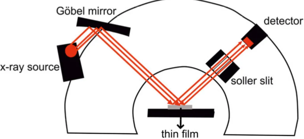
where is an integer, is the distance between the crystallographic planes, is the wavelength of the x-rays, is the angle between the crystal plane and the incident and reflected x-rays. In this study all measurements were done with a CuKα x-ray source, where is 1.54Å. A schematic of the XRD set up is given in figure 1.
Figure 1. Schematic view of the XRD setup.
For this thesis work, the grazing incidence XRD (GIXRD) technique was used. For this technique the x-ray source is kept fixed during the whole scan, and the x-rays hit to the film with a very small angle. By using this technique a larger area on the film plane is illuminated; hence more intense counts are detected by the detector even though the investigated sample is a thin film.
In this thesis work GIXRD was used for the phase analysis of the films, extracting the crystallite size and lattice parameter. To extract the crystallite size , Scherrer’s5 formula was used which can be given as
. (2)
Here is the wavelength of the x-ray, is the Bragg angle, is the full width half maximum of the diffraction peak. is a dimensionless shape fac-tor which is kept constant at 0.9 for all calculations. Although this value of the shape factor is defined for spherically shaped crystallite structures with cubic unit cells,6 traditionally it is used even for differently shaped tures. This value can vary slightly due to different shape and unit cell struc-ture of the material, however since Scherrer’s equation is not a very precise way of determining crystallite size it will not affect the result drastically. Besides that, the unit cell structure of the films investigated in this thesis work is cubic so we assumed taking the shape factor as 0.9 is a good enough estimation.
In addition to crystallite size, the lattice parameter is also extracted by us-ing the XRD data. To extract the lattice parameter the value is first calcu-lated from equation 1. The crystalline structures of the films investigated in this thesis are cubic. For cubic crystals the relation between and the lattice parameter is given as5
where , and are the miller indices. Depending on equation 3, lattice parameters were extracted for the different films.
2.1.2. X-ray reflectivity
X-ray reflectivity (XRR) is a very powerful and widely used technique to obtain the thickness of different layers in thin film stacks as well as their density and roughness, both at the surface and the interfaces. The same ge-ometry as in GIXRD technique is used for XRR. However for XRR the re-flected and refracted X-rays are detected and evaluated instead of the dif-fracted X-rays. Using this technique the intensities of the reflected and re-fracted X-rays are measured with respect to the incident angle of the x-ray beam on the sample surface at very small angles.
Equations explaining the reflectivity properties of visible light, such as Snell’s law and the Fresnel equations, are also valid for reflected X-rays. When they are solved for the defined refraction index of an X-ray, which is slightly less than one, refractions and reflections of X-rays can be analysed.7
Reflected x-ray beams from the surface of a thin film structure, from the interfaces between the layers in the structure and from the substrate interact, and interference occurs between these x-rays and due to these interferences the intensity of the detected X-ray beam oscillates. These oscillations depend on the thickness of the different layers in the film stack and since they were observed by Kiessig for the first time they are known as Kiessig fringes.8
The period of the oscillations depends on the layer thicknesses, and by ana-lyzing the oscillations the layer thicknesses can be extracted. The determina-tion of the thickness of the layers of a film stack is independent of the mate-rial type.7,9 Depending on the roughness of the surface and the interfaces in
the film stack, the decrease rate of the oscillatory x-ray intensity varies. An increase in the roughness of the surface also increases the decaying rate of the detected reflected x-rays. By analyzing the decay rate of the x-ray inten-sity, the surface and interface roughness values can be calculated.9 When it
comes to extracting the material density of different layers, necessary infor-mation is obtained from the position of the edge of total reflection in the X-ray intensity-reflection angle plot. This edge value is also known as the criti-cal angle for the reflection. Since the absorption of x-rays is dependent on the density of the material, the shape and position of this edge provide the necessary information about the material density.7,9
2.2. Magnetic Characterization
Magnetic films are characterized in terms of both static and dynamic mag-netic properties. For static characterization, superconducting quantum inter-ference device (SQUID) and looper setups were used. Dynamic
characteriza-tions were mainly based on ferromagnetic resonance (FMR) measurements. FMR measurements were done in two different ways. The first type of measurement was done in a resonant cavity at constant microwave frequen-cy. The second type of measurement was done with a waveguide, where the microwave frequency was varied in the broad range.
2.2.1. Static Magnetization
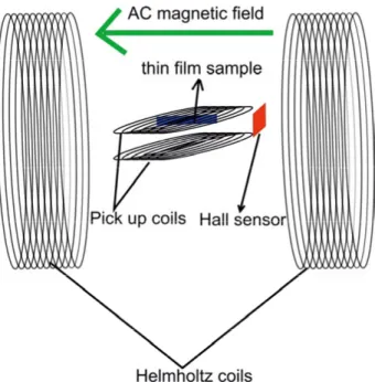
LooperA looper is a setup which measures hysteresis curves of magnetic flux densi-ty versus magnetic field strength, and also known as a looper. Basically a looper consists of two Helmholtz coils and two identical pick-up coils. An AC magnetic field is applied to the Helmholthz coils to change the flux and this may induce a voltage in the pick-up coils. To avoid this problem the pick-up coils are connected differentially. Since they are connected differen-tially, the induced voltage coming from the flux change due to the Helmholtz coils is cancelled out and the voltage induced by the time varying magnetiza-tion of the measured thin film posimagnetiza-tioned in the center of one of the pick-up coils is enhanced. The voltage induced by the thin film sample in the pick-up coil can be defined by Faraday’s law,
. (4)
Here is the cross sectional area of the pick-up coil and is the number of turns. If is integrated over time, the value of B, flux density, is obtained. The magnetic field applied on the thin film by the Helmholtz coil is usually measured by mounting a Hall probe next to the pick-up coil. loopers are generally used for obtaining hysteresis curves since they make very quick measurements possible. However, they are limited when it comes to sensitivity; hence they are suitable for characterizing large samples10,11. In
this thesis work a looper was used for measuring the hysteresis loops of the FeCo thin films, which were deposited on large substrates with a diame-ter of 20.32cm (8 inch). Since the applied field by a Helmholtz coil is limited in magnitude it was only possible to saturate the films when the field was applied within the film plane. So only hysteresis loops of in-plane measure-ments were obtained with this setup. During the measuremeasure-ments, the sample was rotated so the external field was applied both along the easy and the hard axis of magnetization. As a result of these measurements, in plane coer-civity ( ) both for the easy and the hard axis, and the saturation magnetiza-tion ( ) were extracted. A schematic of the principle of operation of the
Figure 2. Principle of a looper. SQUID
When it comes to measuring magnetic flux, the SQUID is one of the most widely used and most sensitive techniques. A SQUID is basically a closed superconducting loop which includes one or two Josephson junctions, re-ferred to as RF and DC SQUID, respectively. The working principle of a SQUID is based on the quantization of flux which is multiples of the con-stant flux quantum given as
2 2.07 10 Wb,
where is the Planck constant and is the charge of the electron. Since the SQUID is a magnetic flux to voltage transducer, exploiting such a small quantity as the flux quantum makes the SQUID to be an extremely sensitive measurement setup. In a DC SQUID the superconducting loop is biased with a DC current and this current passes through the Josephson junctions. De-pending on the external magnetic flux the voltage across the Josephson junc-tions will change periodically with the period of one flux quantum. A change in this voltage is monitored in order to determine the magnetic flux that is coupled to the superconducting loop12,13. A schematic of the working
princi-ple of a DC SQUID is given in figure 3. For this thesis work experiments were done by using an RF SQUID which means that there was only one Josephson junction in the superconducting loop and the loop was inductively coupled to an RF circuit. An RF SQUID with a sensitivity of 10-11 Am2 was
properties measurement system (MPMS) which can apply fields up to 5T. Since the system has such a high sensitivity and can apply such a high field, it was possible to measure small pieces of thin films both with the applied field in-plane and out-of-plane with respect to the film surface.
Figure 3. Schematic of a DC SQUID.
2.2.2. Dynamic Magnetization
The magnetization dynamics of the thin films in this thesis work was charac-terized using frequency domain measurements. Different types of FMR set-ups were used. FMR is a phenomenon which defines different aspects of the resonant magnetization dynamics of the magnetic materials. When a static magnetic field is applied to a magnetic material, the magnetization vector of the material tends to align parallel to the applied field. At this point another external microwave excitation field, which is weak in comparison, is applied perpendicular to the static field and this microwave field excites a preces-sional motion of the magnetization vector around the static magnetic field. The magnetization precesses with a frequency called the Larmor frequency. When the frequency of the microwave excitation field matches the Larmor frequency of the material, resonance condition occurs and the maximum absorption of the microwave signal is observed. The relaxation of the dy-namics often referred to as the damping of magnetization dydy-namics can be extracted by analyzing the absorption line shape of the FMR spectrum. There are different types of FMR setups in terms of measurement geometries and the way of transferring the microwave signal to the sample.
Cavity FMR
A resonant cavity FMR technique was used in this thesis to measure the FMR spectrum of the thin films. An Elexysys setup from Bruker was used for this thesis work. This setup consists of a microwave bridge, resonant cavity and an electromagnet. The microwave bridge is used both as a micro-wave source and a micromicro-wave detector. The micromicro-wave field is transferred to
the cavity via a waveguide. In case the microwave energy is stored in the cavity without any reflection, this condition is called resonance. This is also necessary condition to run a successful FMR measurement. One of the most important characteristic of the cavity FMR setup is quality factor which is ⁄ where is the resonance frequency and is the linewidth of the resonance curve. Standing electromagnetic waves occur inside the cavity when there is resonance. This means that if the magnetic field compo-nent of the wave is maximum at a point in the cavity, then the electric field component should be minimum, or the other way round. During FMR meas-urements, the microwave magnetic field interacts with the magnetization of the film and microwave energy is absorbed at FMR condition, which means if the film is located at the point of microwave magnetic field maximum, the highest sensitivity can be obtained. In this system the cavity and the wave-guide should be coupled which is provided by the iris. The iris is a structure which matches the impedances of the waveguide and the cavity simply by adjusting the amount of microwaves entering the cavity. This is done by changing its size with the help of a screw type structure. When a film is mounted inside the cavity and the magnetic field is swept, resonance micro-wave energy is absorbed by the sample. This absorption changes the Q factor and this change results in the reflection of the microwaves from the resona-tor and recorded as FMR signal.14,15 In the setup used during this work, the
cavity is located between the poles of an electromagnet, which provides a uniform DC magnetic field. An X-band cavity with constant 9.8 GHz mi-crowave frequency is used. The measurement is performed in field-swept mode, and when the magnitude of the DC magnetic field matches the neces-sary condition of FMR, absorption in the reflected microwave is observed by the detector at the microwave bridge. The cavity FMR setup is equipped with a goniometer which allows the sample to be rotated with respect to the DC magnetic field direction. Repeating the FMR measurement for different orientations (angles) of the sample with respect to the DC magnetic field direction allows us to extract the type of magnetic anisotropy and anisotropy fields. Two different types of quartz sample holder rods are used in the setup which allows the film sample to be rotated with the DC magnetic field either in or out of the film plane. This feature of the setup helps to observe differ-ent types of contributions to the magnetic damping. Although it is a draw-back that one cavity can only run at a constant frequency and where you need different cavities to run measurements at different frequencies, cavity FMR is a more sensitive technique compared to other FMR techniques. It is useful when you for instance would like to perform measurements on ul-trathin magnetic films. A schematic of a cavity FMR setup is given in figure 4.
Figure 4. Schematic of the cavity FMR setup.
In-plane broadband FMR
Beside single frequency cavity FMR measurements, broadband FMR meas-urements were done where the sample is put face-down on a coplanar wave-guide (CPW) and FMR is measured in a wide frequency range. In these measurements a homemade setup was utilized. This setup consists of a mi-crowave signal generator, SMF 100A from Rohde&Schwarz, coaxial cables, an electromagnet, Helmholtz coils, a coplanar waveguide with via holes, an RF diode and a lock-in amplifier for signal detection. A picture of the entire set up is given in figure 5. The signal generator can generate frequencies up to 43.5GHz and the signal is transferred to the CPW via coaxial cables. The CPW can handle frequencies up to 40GHz, so limits the setup in terms of frequency. The measurement is performed in field-swept mode with the DC magnetic field applied perpendicular to the microwave magnetic field. Ab-sorption occurs when the magnitude of the DC magnetic field matches the FMR condition. When recording an FMR spectrum, the microwave frequen-cy is set to a constant value and the DC magnetic field is swept. Basically absorption of the power is recorded when the DC magnetic field and the microwave frequency meet the resonant condition. To improve the sensitivi-ty of the measurement and get rid of the noise in the signal, the magnetic field is low frequency modulated by an AC magnetic field with amplitude 0.25mT and frequency 211Hz applied via the Helmholtz coils to modulate the output FMR absorption signal. An RF diode is used to rectify the micro-wave signal to a low frequency modulated DC signal, which is then detected
by the lock-in amplifier. It should be noted that the CPW used in this setup has via holes laid by the central conductor line, which connect the top and bottom layers of the CPW and act as a microwave wall. The created lateral walls in the CPW create another waveguide mode and stops surface waves inside the structure. In order to make it possible that CPW can handle higher frequencies, the distance between these via holes should be less than a quar-ter of the wavelength of the microwave signal.16 When this condition is ful-filled the array of via holes can act as a wall and the high frequency micro-wave signal can be transmitted among these walls without loss or absorption. This feature of the CPW distinguishes it from ordinary CPWs and makes it operable up to 40GHz. End launchers are also used for providing connection and transfer of microwaves between the CPW and coaxial cables. A photo-graph revealing the details of the CPW is given in figure 6.
Figure 5. Photograph of the in-plane broadband FMR set-up.On the top an overall of the set-up is given. On the bottom a zoomed in photo in to the gap between elec-tromagnet poles is given.
Figure 6. Photograph of the coplanar waveguide used for in-plane FMR
measure-ments.
Out-of-Plane Temperature Dependent FMR
The FMR measurements in this geometry are done by applying the DC mag-netic field perpendicular to the film plane at different temperatures by utiliz-ing a custom built setup. The setup used for these measurements consists of a Quantum Design physical properties measurement system (PPMS), a mul-tifunctional probe of the PPMS system, coaxial cables, which can transmit microwaves even at cryogenic temperatures, a CPW, which can also work at cryogenic temperatures and a PNA network analyzer, N5227A from Agilent Technologies. The network analyzer is used both as a source and detector for microwave signals, since it has two ports that measure all parameters of the scattering matrix. The CPW is mounted at the lower end of the multi-functional probe and the sample film is mounted face down on the CPW. The network analyzer can apply microwaves up to 67 GHz. However the CPW can handle frequencies only up to 50GHz, so 50GHz is the limit of the set up in terms of frequency. The PPMS allows a DC magnetic field of up to 9T to be applied, which is applied perpendicular to the film surface. During the measurement, the frequency was set to a constant value on the network analyzer and the applied DC field was swept. The transmitted complex signal was measured by the network analyzer. The measurements are repeated at many different frequencies to be able to extracts the details of the spin dynamics. Since the PPMS is used for these measurements it is possible to cool down the system with liquid helium and run measurements between 4 and 350K. Cables and waveguide were produced in such a way that they can handle cryogenic temperatures. Like the one used in in-plane measure-ments, the CPW used for out-of-plane measurements is also equipped with via holes laid next to the central conductor so it can work up to high fre-quencies. A photograph of CPW used is given in figure 7and the schematic layout of out-of-plane FMR is given in figure 8.
Figure 7. Photograph of the CPW inserted in the PPMS chamber for out-of-plane
FMR measurements.
3.Magnetization Dynamics
3.1. Magnetic Damping
As was explained in the definition of FMR, when a magnetic field is applied on a magnetic material the magnetic moment vector of the material starts precessing around the applied field, and after some time the precession dampens and the moment vector aligns with the applied field vector. Damp-ing of precession and the mechanism behind the alignment of the magnetic moment vector of the material is related to both intrinsic and extrinsic fac-tors that define the damping. Intrinsic damping is called Gilbert damping. However, apart from Gilbert damping, there are a number of extrinsic factors such as two magnon scattering (TMS), eddy current damping, spin pumping into a nonmagnetic metal, radiative damping, and contributions coming from the inhomogeneity and mosaicity of the sample. Understanding the damping properties of thin film materials is quite important since the damping mecha-nism defines how suitable they are for daily life applications. For some ap-plications a low damping parameter is required since materials with a low damping parameter require low critical switching current for magnetic switching.17–19 However, a higher damping parameter is essential for faster
switching of magnetization, especially for memory applications.20
3.1.1. Gilbert Damping
As mentioned before, to observe the damping a magnetic field should be applied on the magnetic thin film. However, when it comes to the applied static magnetic field, the term effective field should be introduced first. Total magnetic energy density of a magnetic thin film consists of different energy contributions such as exchange energy, Zeeman energy, demagnetiz-ing energy, cubic anisotropy energy, uniaxial anisotropy energy, perpendicu-lar anisotropy energy and surface anisotropy energy. In order to make the system stable and get to an equilibrium state some of these energies should be minimal.21,22 When the derivative of the total energy is calculated
with respect to the magnetization vector , we get the effective magnetic field , as given in equation,
When a static magnetic field is applied on a magnetic film, the magnetiza-tion vector tends to align parallel with , and when a small microwave field is applied perpendicular to the the magnetization vector starts a precessional motion around . This precessional motion is defined by the Landau-Lifshitz (LL) equation of motion21,22.
μ . (6)
Here γ is the gyromagnetic ratio, where | | 2⁄ . is the Landé-g factor, is the mass of the electron and is the charge of the electron. However, the precessional movement of the vector does not last forever, and after a period of time the vector again tends to align with . This behavior is called damping. In the LL equation the damping term is missing and when a term which defines damping is introduced, the equation is called the Landau-Lifshitz-Gilbert (LLG) equation since the damping term was first introduced by Gilbert23. The LLG equation is given as,21,22,24
μ . (7)
Here is the dimensionless Gilbert damping constant, which defines how fast the precessional motion dampens and the vector aligns with . It should also be mentioned that the vector given in this equation keeps the magnitude conserved during this damping process. The Gilbert damping is an intrinsic property of the films. The origin of this damping is basically spin orbit coupling.25,26 In addition to spin orbit coupling it is possible to explain
intrinsic damping by scattering of electrons by phonons and magnons. In the case of phonon scattering the process is mediated by spin orbit interaction however in the magnon scattering case angular momentum relaxes as scat-tered electrons repopulate the magnetization-direction-dependent Fermi vol-ume. Relaxation of magnon modes occurs through exchange interaction with a conduction electron. Afterwards the spin of conduction electron relaxes to the lattice through spin orbit interaction. 27
3.1.2 Two Magnon Scattering
Two magnon scattering (TMS) is one of the extrinsic contributions to mag-netic damping which increases the linewidth of the FMR absorption, hence the value of damping. When FMR condition occurs, quantized spin waves, known as magnons, may be excited, which precess as a wave defined by the wavenumber . When the precession is uniform, 0. Then, these uniform spin waves can be scattered at scattering centers, to degenerate, non-uniform states where 0 and dissipate energy into the lattice. This process is called TMS. 28–30 In the magnetic films TMS can occur depending on the
affect-ing the extrinsic relaxation by creataffect-ing scatteraffect-ing centers for the TMS pro-cess, grains can also affect the increase of the damping parameter. Larger contributions of TMS to the relaxation can be observed depending on the grain size and anisotropy field.30 The TMS process is highly dependent on
the measurement geometry. As mentioned in the section 2.2.2, broadband FMR measurements were run in two different geometries where the DC magnetic field was applied within the film plane and out of the film plane. The TMS process is angle dependent when the DC field is applied within the film plane,29 which may be used to extract information about the TMS
con-tribution to the measured damping parameter. The TMS concon-tribution can also be revealed by studying the frequency dependence of the FMR absorp-tion linewidth, which should exhibit a nonlinear behavior if the measure-ments have been performed in a wide enough frequency range.34 However,
when the FMR measurement is done by applying the DC field out of the film plane the TMS effect is suppressed.29,34,35 Therefore, out-of-plane FMR
measurements are preferable in order to get rid of the TMS contribution and get a damping value which is closer to the intrinsic Gilbert damping parame-ter.
3.1.3. Eddy-Current Damping
Eddy-current damping is another extrinsic contribution to damping which comes from the interaction of the measured film with the high frequency microwave magnetic field. Eddy-current damping can be explained as a re-laxation process caused by screening of the electromagnetic microwave field by the conduction electrons of the investigated film.22 A more macroscopic
explanation is that an AC voltage is induced when a conducting material is exposed to a time varying magnetic flux created by the microwave magnetic field and the precessing magnetic moment. This fundamental phenomenon is known as Faraday’s law. AC currents are induced both in the CPW and in the ferromagnetic thin film when the spins precess in the conducting film. Energy dissipation due to these induced eddy currents is known as eddy-current damping.36 It should be mentioned that eddy-current damping is a
thickness dependent contribution to the relaxation. If a film is thin enough eddy current damping is negligible but thick films, on the other hand, are exposed to a higher eddy-current damping contribution.37,38 The critical thickness required for a conducting film in order to induce a significant eddy current damping is defined by the skin depth, which can be explained as the depth below the surface of the film where the microwave magnetic field and the density of the current drops to 1⁄ of the their values at the surface. When the thickness of the film is comparable to or larger than the skin depth, then eddy-current damping becomes significant.22
3.1.4. Radiative Damping
Radiative damping is a contribution to the relaxation which works in a simi-lar way to eddy-current damping and comes from inductive coupling of the CPW and the measured thin film.39 Basically, as explained in the eddy
cur-rent damping section 3.1.3 precessing spin waves induce eddy-curcur-rents which dissipate energy. The contribution to the magnetic damping caused by eddy-currents induced in the CPW is known as radiative damping.36
3.1.5. Spin Pumping
When the thin film structure is a stack of layers which includes a ferromag-netic layer and adjacent nonmagferromag-netic metallic layers, it is possible to observe an enhanced damping parameter in such structures. Since spin currents are generated at the interface between a ferromagnetic layer and a nonmagnetic metallic layer due to the precessing magnetization, spin angular momentum can be injected into the nonmagnetic adjacent layer and relaxed in that layer. This relaxation enhances the damping in such structures.22,34 This
phenome-non is observed when there is a stronger spin orbit coupling in the phenome- nonmag-netic layer and it is also thickness dependent, so if the nonmagnonmag-netic layer thickness is less than the spin diffusion length, then spin pumping contribu-tion is negligible.22,40
3.1.6 Mosaicity Contribution
Mosaicity in the thin film structure could also be a source of enhanced relax-ation. If the crystallite orientations, internal fields and thickness of the film vary from one region to another within the film structure, then all of these individual regions can have slightly different resonance fields. The overall FMR signal will include a superposition of these local absorption contribu-tions and will thus result in a broader absorption FMR linewidth, which means larger damping.41–43
3.1.7. Inhomogeneity Contribution
Finally, it is also well-known that there is an extrinsic contribution to the magnetic relaxation due to inhomogeneity in the film structure, which is a frequency independent contribution. This inhomogeneity is caused by local variations of the magnetization and internal magnetic fields. This contribu-tion is also defined in terms of inhomogeneity of local demagnetizing fields.44–46 In some cases this contribution can also be thickness dependent due to dispersion of the anisotropy in the films which increases by decreas-ing of the film thickness.34
3.2. Equations for Analyzing Magnetization Dynamics
3.2.1. Cavity FMR Analysis
In cavity FMR analysis the absorption of the microwave power is measured with respect to the applied DC field, and the signal recorded by the equip-ment comes in the shape of the field derivative of the absorption. The reason for this is that the DC magnetic field is modulated by a low frequency AC magnetic field. The recorded raw data can therefore be fitted to the equation47
∝ , (8)
where is the magnetic field derivative of the microwave absorption. The resonance field and the full width half maximum of the FMR absorption linewidth were extracted from the raw data by fitting the data to this function. Hence these parameters were used as fitting parameters for the fitting. Since cavity FMR measurements are angle-resolved measurements, plotting angle dependent and values gives further understanding of the magnetic properties of the thin film samples.
When the values were extracted with respect to angle from in-plane measurements, they were fitted by using the equation40
cos cos 4 cos 2
3 cos 4
cos . (9)
In equation (9) is the constant frequency of the setup which is 9.8GHz and is the resonance field. , , and are the directions of the mag-netic field, magnetization, uniaxial and cubic anisotropy, respectively, with respect to the 100 direction of the thin film substrate. and are the uniaxial and cubic anisotropy fields, respectively, where and . Here and are the uniaxial and cubic magnetic anisotropy constants. is the effective magnetization and is defined as
angle-resolved data were fitted to equation (9), , and were used as fitting parameters. Extracted and values, in conjunction with the pat-tern of the angle resolved plot, clearly reveal the type of dominant in-plane anisotropy in the film and the angle-resolved cavity FMR analysis is thus a very useful technique in this sense.
3.2.2. In-plane Broadband FMR analysis
FMR absorption spectra were recorded via the lock-in detection technique for in-plane broadband FMR measurements; hence the recorded microwave power versus magnetic field pattern comes in the shape of a derivative func-tion. Since we have a derivative function shape, the same equation (8), as used in the extraction of and for the raw data recorded in cavity FMR measurement, was used here as well. Once the resonance fields are ex-tracted for different frequencies, an versus frequency graph was plotted and fitted to an equation which is valid for the in-plane measurement geome-try. The equation used for the in-plane measurement case can be modified depending on whether the DC magnetic field is applied along the easy axis or the hard axis of the film. In the equation set given below first equation is written for the easy axis and the second one is written for the hard axis.48
(easy axis),
(hard axis). (10)
and were used as fitting parameters and the corresponding values were extracted.
Apart from the values, extracted values were also plotted versus frequency and this plot was fitted to equation48
μ Δ μ Δ , (11)
where is the total damping parameter, including both intrinsic and extrin-sic contributions, and Δ is the extrinsic frequency independent contribu-tion to the linewidth of the absorpcontribu-tion spectra. The main purpose of this fit-ting was to extract the total damping parameter of the film and disfit-tinguish the frequency independent contribution to the linewidth.
3.2.3 Out-of-plane Broadband FMR analysis
Out-of-plane FMR data were recorded by using a network analyzer instead of the lock-in technique used for the in-plane measurements. The transmitted complex parameter was detected via the network analyzer and the raw data were fitted to the equation set given below:49
, ,
, (12)
where . Here is the complex transmission parameter of the microwave signal where is the nonmagnetic contribution to . 0is a frequency and film thickness dependent imaginary function, and is the complex magnetic susceptibility of the film. is a phenomenological com-plex coefficient which is used for correction of the drift, depending on the time, coming from the measurement electronics. and were used as fitting parameters and extracted from the fitting of raw data to equation (12). Extracted values were plotted versus frequency and this graph were fitted to the linear function49
μ μ , (13)
which enabled the extraction of and the Landé -factor. Δ values versus frequency were plotted and fitted to equation (11) in the same way as in the in-plane analysis and the damping parameter and frequency-independent extrinsic linewidth contribution were extracted.
3.2.4. Subtracting Some Extrinsic Relaxation Contributions in
Out-of-plane Measurements
Eddy current damping
Eddy current damping in the system can be calculated and subtracted from the total damping value of the film by using the equation,36,38,40
, (14)
where is a coefficient which defines the eddy-current distribution in the thin film structure. A decrease in the value of means larger localization of eddy currents in the film. and are the resistivity and thickness of the film, respectively. The ideal way of obtaining is to subtract all other ex-trinsic parameters from the total damping for samples with different thick-nesses and to measure the resistivity of the films for different thickthick-nesses and then plot the remaining damping parameter versus and extract the value from the linear fit.
Radiative damping
The radiative damping contribution in the system can be calculated and sub-tracted from the total damping by using the expression,36,39,40
, (15)
where is a dimensionless parameter that accounts for the FMR mode pro-file, and are the thickness and length of the sample on the waveguide, respectively, is the width of the center conduction line of the CPW and is the impedance of the CPW.
It is also possible to determine the radiative damping contribution in the system experimentally. When a glass spacer with large enough thickness is placed between the CPW and the sample, the radiative damping contribution becomes negligible.36,39,40
Spin pumping
The contribution to magnetic relaxation due to spin pumping through inter-faces within the film can be described by the equation,39
↑↓
, (16)
where ↑↓ defines the effective spin-mixing conductance. It should also be mentioned that equation (16) is given just for the simplest case of one inter-face in the film structure. It is also possible to have a sandwich type structure with two identical interfaces. Then a coefficient of 2 should be added to the equation.39 The ideal way to extract ↑↓ is to first measure the damping
parameter of identical films with different thicknesses and then subtract all other extrinsic damping contributions from the total damping parameter and then plot the remaining spin-pumping contribution versus film thickness and fit that plot to equation (16) and extract ↑↓ as a fitting parameter.
4. Dynamic Properties of Co
2FeAl Thin Films
This thesis is mainly structured around investigations of two different types of magnetic alloys in terms of the dynamic magnetic properties. One of these alloys is Co2FeAl, which is also known as a full Heusler alloy, and the other
is Fe65Co35. In this chapter material properties, the structural and magnetic
characterization of Co2FeAl are covered and the next chapter is about
Fe65Co35. This chapter is based on the work done in collaboration with Sajid
Husain and Sujeet Chaudhary from Indian Institute of Technology Delhi, whom contributed for paper I, II, III and IV.
4.1. Material Properties
Today, intensive fundamental research is being done on Heusler alloys and in particular on Co-based Heusler alloys and the specific composition Co2FeAl. These alloys possess unique properties, such as high Curie
temper-ature ( 1000 ), full spin polarization at Fermi level, which is also in-terpreted as half metallicity and high magnetization all of which are favora-ble properties for future spintronic applications in terms of producing faster and more energy efficient devices.50–57
Co2FeAl belongs to the structure family known as full Heusler alloys and
has an X2YZ structure with three different phases. These three phases are
labelled L21, B2 and A2, which are fully ordered, partially ordered and fully
disordered, respectively. In the L21 phase, the different types of atoms
occu-py the sites which are individually assigned for them. This structure depicts the full spin polarization at the Fermi level and is known as a half-metallic structure.58 In the B
2 phase, Y and Z atoms, Fe and Al particularly in our
study, share their sites randomly. A2 phase is the name of the structure where
all sites are randomly occupied by all different types of atoms.53,58–60
Physi-cal properties of the films, and especially the half-metallicity of the produced thin films, are strongly dependent on the organization of the atoms within the crystalline structure. Half-metallicity or full-spin polarization is obtained when all atoms are fully ordered, as in the L21 phase. Disorder in the crystal
structure ends up adding extra states at the Fermi level, which reduces the spin polarization, hence the half-metallicity.50,61 Reduced spin polarization
In this thesis work, the ion-beam sputtering technique was used in order to deposit all Co2FeAl thin films as explained in paper I.62 Firstly, different
films were deposited on Si(100) substrate in order to investigate the effects of deposition temperature on film structure. These samples deposited at dif-ferent temperatures were used for the first part of the study. The substrate temperature was fixed at 300K, 573K, 673K and 773K. Co2FeAl films were
deposited at these temperatures with a nominal thickness of 53 nm and then capped with Ta with a nominal thickness of 2nm. Further details about the film deposition technique are explained in paper I. Structural analysis was done on these films in order to determine the crystallographic phase of the films, and then magnetization dynamics was investigated in order to under-stand the relation between the crystallographic phase and damping parame-ter.
Further study was done when the growth conditions were optimized. As a second part of the study, the effect of different seed layers and capping lay-ers were investigated in terms of magnetization dynamics in order to under-stand the interfacial effects on magnetic damping. Information extracted from these studies would be useful for producing structures that make use of spin-transfer torque in spintronic devices. In this part, firstly, thin films of Co2FeAl were deposited on a Si(100) substrate where a seed layer of Ta with
nominal thickness of 10nm was added between Co2FeAl and Si. The
nomi-nal thickness of the Co2FeAl was kept constant at 8.4nm for all samples. One
of the Co2FeAl films was kept without a capping layer and two of them were
capped with MgO and Ta with nominal thicknesses of 2nm and 4nm, respec-tively. During the deposition process the Ta seed layer was annealed at 673K for 30 minutes before the deposition of Co2FeAl. After the deposition was
completed all samples were annealed at 523K for one hour.
Beside studying structures with MgO capping and Ta seed, Co2FeAl films
were deposited with different thicknesses and Ta capping just to understand the effect of varying thicknesses and Ta interface on magnetic damping. For this part of the study Co2FeAl films were deposited on Si(100)/SiO2 with a
capping layer of Ta. The nominal thickness of the Ta was 5nm and the nom-inal thickness values of Co2FeAl were 8, 10, 12, 14, 16, 18 and 20 nm.
Again the substrate temperature was kept constant at 573K since it is the optimal growth temperature determined in the initial part of the study. Re-sults of this investigation revealed mainly the effect of the spin pumping contribution to the magnetic relaxation which occurs at the interface of Co2FeAl and Ta. Apart from this the trend in behavior of magnetic damping
with respect to Co2FeAl thickness was determined.
In addition to the investigation of the effects of different interfaces of nonmagnetic layers, the magnetization dynamics of Co2FeAl films were
studied in a temperature-dependent way. For this part of the work Co2FeAl
films were again deposited on a Si(100) substrate where the substrate tem-perature was fixed at 573K, 673K and 773K. As was understood from the
first part of the study, substrate temperature during film deposition is the key factor which determines the crystal phase of the film. The reason for deposit-ing samples at different temperatures was to study the temperature depend-ence of the magnetic damping for films with different degree of structural order. These Co2FeAl films were deposited with a nominal thickness of 50
nm and were capped with Al with 4 nm nominal thickness. In order to get the fully disordered phase of Co2FeAl, one film was deposited at 300K and it
was capped with Ta. Related information about deposition parameters used in order to obtain a fully disordered phase is explained elsewhere.63 Detailed
analysis of the temperature-dependent damping profile of Co2FeAl films
with different crystal phases revealed the temperature dependent trend of magnetic damping. In this part of the study extrinsic magnetic relaxation contributions such as eddy-current damping and radiative damping are dis-cussed in detail. Beside experimental studies, theoretical calculations about how intrinsic Gilbert damping behaves with respect to temperature were performed in this part of the study. By subtracting the extrinsic relaxation contributions, intrinsic Gilbert damping values were obtained experimentally and they were compared with calculated values.
As a final part of the investigation of Co2FeAl, Co2FeAl films were
de-posited with ultrathin thickness in order to investigate the effects of interface anisotropy on the magnetic properties and to observe perpendicular magnetic anisotropy. It is known that perpendicular magnetic anisotropy (PMA) can be obtained in ultrathin layers of a 3d ferromagnetic element or alloy in di-rect contact with an oxide.64 The origin of the PMA is hybridization between
the ferromagnetic 3d orbitals and the oxygen 2p orbitals of the oxide, and this is therefore referred to as interfacial anisotropy. The hybridization be-tween these orbitals makes the energy for 3d orbitals pointing towards the interface (3dxy, 3dxz and 3dz2) smaller than the energy for orbitals with
pla-nar symmetry (3dxy and 3dx2-y2), resulting in a strong PMA. Systematic
studies have shown that the PMA requires optimally oxidized stoichiometry of the oxide,64 implying that both under- and over-oxidized stoichiometry of
the oxide will prevent the magnetic layer from exhibiting PMA. Since inter-facial PMA has been shown to exist for ultrathin layers of Co2FeAl in direct
contact with MgO,65 we decided to make a detailed study of PMA in Co2FeAl /MgO structures. Prior to deposition, the Si(100) substrate was
treated with HF solution to remove the native SiO2 layer and then
immedi-ately loaded into the high vacuum chamber of the ion-beam sputtering depo-sition system. A series of thin film Si/Ta(10 nm)/Co2FeAl ( )/MgO(2
nm)/Cr(2-3 nm) structures were prepared, with the nominal thickness of Co2FeAl varying the range 1 1.8 nm. The growth steps were as
fol-lows: Ta was room temperature (RT) deposited and then annealed at 400 oC
for 30 minutes; Co2FeAl was grown at RT; MgO was grown at RT and then
the trilayer stack was annealed at 280 oC for 60 minutes; and the structure
4.2. Analysis and Results
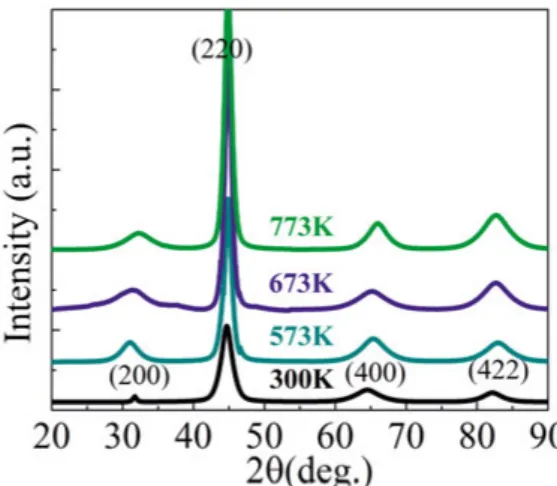
In the initial part of the study samples were first characterized in terms of their structural properties. Since the magnetization dynamics of these films are closely related to the crystal phase, this study was necessary before ana-lyzing the magnetic properties of the samples. When the data coming from measurements related to structural analysis were interpreted and film deposi-tion parameters were optimized then this informadeposi-tion was used for further parts of the study. XRD and XRR were the mostly used methods when it comes to structural characterization in this thesis work. First of all, XRD measurements were done on films deposited at 300K, 573K, 673K and 773K in order to resolve whether the crystal phase of the film was A2, B2 or L21. In
the XRD pattern a peak from (200) diffraction was accepted as evidence of the formation of B2 phase (paper I). However, it is necessary to observe
dif-fraction peaks from (111) and (311) planes as evidence of the L21 phase.66
XRD spectra of the films are given in figure 9.
Figure 9. XRD spectra of the films prepared with stacking of Si/Co2FeAl/Ta which
were deposited at different temperatures (paper I) (the figure was taken from the article “Growth of Co2FeAl Heusler alloy thin films on Si(100) having very small
Gilbert damping by ion beam sputtering”, S. Husain et al., Scientific Reports 6, 28692 (2016)).
Appearance of the (200) peak for all films deposited at different tempera-tures is clear evidence of the presence of B2 phase in all films. As well as
(200), diffraction from (220), (400) and (422) planes were observed as well. The appearance of these peaks is because of the polycrystalline structure of the prepared films (paper I). When it comes to distinguishing the L21 phase, it
is difficult to resolve whether the structure is B2 or L21 by just relying on
employing the Webster model along with the approach of Takamura et
al.40,67 According to this approach the degree of B
2 ordering can be given as
⁄ ⁄ , (17)
where ⁄ is the intensity ratio of diffraction from (200) and (220) planes, obtained experimentally. is the intensity ratio for the (200) and (220) peaks, which is theoretically calculated for the B2
phase.68 S
B2 values, for samples investigated in the temperature-dependent
study part of the thesis, which were deposited at 573K, 673K and 773K are ~90%, ~90%and ~100%, respectively.68 The ratio of ⁄ was extracted
as ~30 for all three samples deposited, which is comparable with the theoret-ical value for perfect B2 order.69,70 When it comes to the L21 phase, extracting
the value of ordering parameter SL21 is also dependent on the ordering degree
of the B2 phase. It is possible to calculate the ordering degree of the L21
phase depending on the intensity ratio of (111) and (220) peaks, given as ⁄ , in conjunction with the SB2 parameter.67 However, a diffraction
peak coming from the (111) planes was not obtained in the XRD spectra for any of the samples. This can be due to the fact that the theoretical intensity of the (111) peak is just 3% of the principal (220) peak. In this manner it is very difficult to analyze the L21 phase just depending on the XRD analysis.
Since magnetic properties are strongly dependent on the crystalline ordering of the Co2FeAl films further discussion will be done in the coming part of
this chapter on the structure depending on the magnetic analysis of the films. Beside films deposited at 573K, 673K and 773K, the film deposited at 300K and capped with Ta, did not reveal any (200) diffraction peak 63, which can
be interpreted as this film exhibits the A2 crystalline phase.
In addition to XRD analysis, the XRR technique was also used to analyze the surface and interface roughness of the films, as well as to obtain accurate thickness values of the different layers within the film stacking. For the films prepared for the initial part of the study, which have a stacking of Si/Co2FeAl/Ta, an oxidized surface layer of Ta with Ta2O5 structure was
observed. The surface roughness of the Co2FeAl films varies in the range
between 0.41(0.03) and 1.23(0.03)nm, where the roughness increases with increasing deposition temperature. Full detailed information, including sur-face roughness, density and thickness of individual layers within the film stack is given in paper I. In the second part of the study, XRR was only done for the stacking of Si/Ta/Co2FeAl/MgO where there is a surface roughness
of 0.10 nm. XRR measurements performed on the Si/Co2FeAl/Ta stacking
again revealed that there is an oxidized Ta2O5 layer on top of the Ta capping
layer. The surface roughness of the Co2FeAl layer varies between
Regarding the magnetic properties of the deposited films, first Co2FeAl
films deposited at different temperatures were investigated by using the magneto-optic Kerr effect (MOKE) technique. Normalized hysteresis loops for samples deposited at different temperatures are given in paper I. Perfect square-shaped hysteresis curves were observed when MOKE measurements were done along the easy axis of the samples, which reveals that samples are almost defect free. When the measurement was varying the in-plane azi-muthal angle, a uniaxial anisotropy was observed. values of the films were extracted via MOKE measurements. values of the samples were measured using the vibrating sample magnetometer (VSM) option of the PPMS setup. A presentation of and values with respect to deposition temperature is given in paper I. The extracted values are in reasonable agreement with the 5.0µB/f.u value of bulk Co2FeAl.53 The increase in
and decrease in by increasing temperature can be attributed to the improved ordering.
In addition to the magnetometer measurements, films were also investi-gated in terms of magnetic dynamics in order to decide which deposition temperature was the optimum in terms of obtaining the most favorable dy-namic properties. In this part of the work, FMR measurements were done by applying the static magnetic field within the film plane. The measurements were performed in field sweep mode for frequencies between 6 and 12 GHz in steps of 1 GHz. Recorded raw FMR spectra were fitted to symmetric and antisymmetric derivative Lorentzian functions, as given in paper I, in order to extract and values. Extracted values were plotted versus fre-quency and this plot was fitted to the Kittel equation, and as a result of this fit the effective magnetization and the in-plane uniaxial anisotropy field were extracted. Depending on the deposition temperature, varies between 1 and 25 Oe. As explained in section 3.2.1, is dependent on and ⫠. In this thickness regime, perpendicular anisotropy is not
ex-pected in the films, hence it is exex-pected that the values to be similar to the values. As given in paper I, varies between 1.2 and 1,29 T whereas varies between 1.34 and 1.4 T. The small offset between extracted from magnetometry and the extracted from dynamic measurements can be attributed to difficulties and errors in determining the exact magnetic volumes of the films used in the magnetometer measure-ments. μ Δ values were plotted with respect to frequency and fitted to equation (11). By this fit, an value of 0.00150.0001 was obtained for the film deposited at 573K, and this value is comparable to the lowest values obtained for this alloy .70,71 It should be mentioned that both of these studies
in literature include a post-annealing process of the as deposited films and both of the films were deposited on MgO substrates. However, in our case, post-annealing was avoided and the films were deposited on a Si substrate, which is a commonly used material in industrial applications. In addition to the value, equation (11) includes a frequency independent linewidth term