Misfit – Impact on Porcelain Fracture and
Screw Loosening of Implant-supported FDPs
- A Laboratory Pilot Study
Caroline Svedberg
Ida Linde
Supervisor:
Christel Larsson, Department of Prosthodontics
Master Thesis in Odontology (30 ECTS)
Malmö University
Program of Dentistry
Faculty of Odontology
February, 2017
205 06 Malmö
Abstract
Aim: The aim of this laboratory pilot study was to investigate whether a misfit between an implant
and a FDP increase the risk of cracks, chip-off fractures and screw loosening of screw-retained implant-supported FDPs.
Material and Method: Twenty screw-retained five-unit implant-supported FDPs were made in
titanium with veneering porcelain. The specimens were evenly distributed into a test and control group. In the test group a misfit of 150 µm was created between the implant and FDP at position 5. All specimens underwent artificial aging in a cyclic loading machine for 100 000 cycles. Visible cracks and chip-off fractures were recorded during and after the test and the specimens were controlled for screw loosening.
Results: Visible cracks within the porcelain veneer occurred significantly more often in the test
group compared to the control group. Nine FDPs in the test group presented visible cracks,
compared to one in the control group. Three chip-off fractures were recorded in the test group, none in the control group. This difference was not statistically significant. The retorque values of the screws presented no statistical significant differences neither between the implant positions nor the groups. None of the screws in the groups were loose.
Conclusion: Within the limitations of this pilot study the results indicate that the presence of a
misfit may increase the risk of cracking and/or chip-off fractures. Further studies are needed to confirm these findings.
Misfit - Inverkan på Förekomsten av
Porslinsfrakturer och Uppskruvning hos
Implantatstödda Brokonstruktioner
- En Laborativ Pilotstudie
Caroline Svedberg
Ida Linde
Handledare:
Christel Larsson, Avdelning för Oral protetik
Examensarbete (30 Hp)
Malmö Högskola
Tandläkarprogrammet
Odontologiska fakulteten
Februari, 2017
205 06 Malmö
Sammanfattning
Syfte: Syftet med denna laborativa pilotstudie var att undersöka huruvida en misfit mellan ett
implantat och en skruvretinerad bro ökade risken för sprickor och chip-off frakturer i porslinet, samt risken för uppskruvning av implantatskruvarna.
Material och metod: Tjugo stycken implantatstödda skruvretinerade femledsbroar tillverkades i
titan med ytporslin. Provkropparna fördelades lika mellan en testgrupp och en kontrollgrupp. I testgruppen skapades en misfit på 150 µm mellan bron och implantatet vid position 5.
Provkropparna genomgick artificiellt åldrande i en cyklisk belastningsmaskin i 100 000 cykler. Synliga sprickor och chip-off frakturer noterades under och efter testet och skruvarna kontrollerades gällande uppskruvning.
Resultat: Synliga sprickor i porslinet uppstod signifikant mer frekvent i testgruppen i jämförelse
med kontrollgruppen. Nio broar i testgruppen uppvisade sprickor jämfört med en bro i
kontrollgruppen. Tre chip-off frakturer uppstod i testgruppen jämfört med noll i kontrollgruppen, skillnaden var inte statistiskt signifikant. Vid kontroll av implantatskruvarna sågs inga signifikanta skillnader mellan varken implantatpositioner eller grupper gällande retorque-värde. Inga av
skruvarna var lösa.
Slutsats: Inom denna studies begränsningar tyder resultaten på att närvaron av en misfit mellan
implantat och överkonstruktion kan öka risken för sprickbildning och/eller chip-off frakturer. Vidare studier krävs för att bekräfta dessa resultat.
Index
Introduction ... 6
Tooth- vs. implant-supported restorations ... 6
The implant system ... 6
Differences between the tooth and an implant ... 7
Complications ... 8
Fit ... 8
Screw loosening and fit ... 9
Porcelain fractures and fit ... 9
Research question ... 9
Aim ... 9
Hypothesis ... 10
Material and method ... 11
Manufacturing of the specimens ... 11
Randomization and embedment ... 11
Cyclic loading test ... 12
Statistical analysis ... 13
Results ... 14
Cracks ... 14
Chip-off fractures ... 15
Screw loosening and retorque value ... 16
Discussion ... 17
Discussion of the material and method ... 17
Discussions of the results ... 19
Conclusion ... 20
Introduction
In the rehabilitation of missing teeth, implant treatment has become increasingly more common due to its range of solutions. The population is moving towards having a higher average life expectancy and the patients expect an adequate treatment that provides excellent aesthetic and function that will last for many years. However, the treatment is not totally without problems and a relatively high frequency of complications has been reported. (1)
Tooth- vs. implant-supported restorations
Lost teeth can be replaced by using many different restorations and materials depending on the situation, location, condition etc. When it comes to multiple missing adjacent teeth removable partial denture (RPDP) or fixed dental prosthesis (FDP) can be used for rehabilitation. FDPs can be implant-supported, tooth-supported or a combination of both. Implant-supported restorations are favourable compared to tooth-supported FDPs when neighbouring teeth are intact or not optimal as abutments. It is advantageous to use an implant-supported FDP instead of a removable partial denture when the patient cannot accept or adapt to the RPDP, retention is insufficient, too few abutment teeth exist or when phonetic, aesthetic, masticatory or functional problems exists. However, an implant surgery can in some situations be a risk and thereby not recommended. Economy, age and location of the missing teeth are other reasons why implant treatment is not to prefer. (1)
The implant system
The implant system is composed of three main components; dental implant, abutment and restoration. These parts have various designs, are composed of different materials and have
different surface properties. The dental implant is the part of the implant system that is anchored in the jawbone, and therefore often defined as endosseous. Commercially pure titanium (c.p. titanium) is the dominating dental implant material because of its ideal biocompatibility, high strength and corrosion resistance. (1,2) Due to these factors, and the capability to osseointegrate, titanium is the best suited material for this purpose (3). The abutment is usually screw retained but in some
instances the abutment and the crown are in one complex retained directly to the dental implant by a screw (4).Titanium abutments are “gold standard” due to high survival rates when used in fixed restorations but alternative materials are available such as gold, alumnia and zirconia (5).
Implant-supported restorations may be either screw- or cement retained. A screw-retained restoration got the advantage of being retrievable, which is beneficial when complications occur. Advantages of cement-retained restorations are the reduced cost, less chair-side time and an easy procedure. (6) Nevertheless, excess of cement can penetrate deep into the tissue and cause infections and fistulas around the implant due to the lack of Sharpey’s fibres (7).
When manufacturing implant-supported FDPs, the most common materials used are metal-ceramic, metal-acrylic or all ceramic. Porcelain-fused-to-metal with a precious alloy has been the “gold standard” for many years (8). Because of the high gold price today, a commonly used metal alloy is cobalt-chromium. In recent years, titanium has become a popular material because of its excellent biocompatibility, favourable physical and mechanical properties, relatively low cost and resistance to corrosion (9). In the choice between ceramic and acrylic veneering, many patients and clinicians prefer ceramic teeth for aesthetic reasons. (10) Feldspar-based porcelain is fused as a veneer onto the metallic framework providing aesthetic and optical properties similar to that of the tooth. The metal provides strength to the restoration since the porcelain is a brittle material not equipped to tolerate the tensile stresses. The veneering process is however technique sensitive and dependent on
the technician’s skills and the handling of the materials. Several factors may affect the risk of porcelain fracture, especially when fused to titanium: phase transformation and thickness of the titanium oxide layer, the thermal expansion coefficient (TEC) and the design and thickness of the porcelain. To avoid phase transformation, mismatch in TEC and a too thick oxide layer, a low-fused porcelain is needed to decrease the risk of fracture. However, a low-fused porcelain has a lower bond-strength when compared to conventional metal-ceramics. If the oxide layer becomes too thick, there is a risk that an adhesive fracture occurs either within the oxide layer or between titanium and oxide layer. (2) A porcelain failure can be observed as cracks, chip-off fractures and bulk fractures, but the definition differs (11, 12). Other terms used are: minor, major, extensive, cohesive,
adhesive, acceptable and unacceptable. Although chipping rarely lead to replacement of the
restoration it is an important factor to discuss. A veneering material fracture creates a rough surface, and sometimes sharp edges, that often leads to some need for adjustment. It can also affect function and aesthetics (12).
Differences between the tooth and an implant
The tissue surrounding the implant has many similarities with that of the tooth, but also some important differences. The periodontal ligament (PDL) surrounding the tooth is comprised of fibres forming a meshwork that anchors the cementum of the tooth to the bone, Sharpey's fibres. Except linking, PDL function to provide stability, protection, support and to give the masticatory system sensory input. (13) The implant lacks these PDL-fibres and thereby the function they provide. The tooth also has fibre bundles that run in the free gingiva around the tooth attaching to the cementum called peripendicular fibres. The implant also has these perpendicular fibres but not as arranged, structured and organised as the fibres surrounding the tooth. (7)
The innervation of the tooth contributes to a good sense of touch, occlusal perception, mastication, swallowing and the awareness of hardness and texture. The enamel-dentine-pulp complex and the mechanoreceptors in the periodontium provide feedback that controls the jaw muscles. These receptors have a good ability to detect low forces and are involved in the fine motor control of the jaw. The rate and direction of the low forces are carefully detected and the information is used to place the food correctly between the teeth so that the food is crushed thoroughly and in the right direction during mastication. This precise and carefully coordinated motor activity is automatic and controlled successfully by the brain. The implant, on the other hand, can be compared to a tooth blocked by local anaesthesia; both the sensory input and the movements of the jaw functions acts the same, but the fine motor control is impaired. Despite this, the patient is still able to function properly but the reduced fine motor control makes the implants cumbersome and the chewing forces may be applied in the wrong direction. (14) This may be an explanation to why fixed implant-supported restorations have a higher complication rate compared to tooth-implant-supported restorations (14, 15).
Osseoperception is a term that explains the capability of transmitting sensation through the osseointegrated implant, restoring the perception in the area of a former tooth. Receptors in the bone, periosteum, joint capsule or other tissues are assumed to explain the restored sensation. Risks of overloading the dental implant are reduced due to the restored response to mechanical stimuli. The mechanical perception in bone is however, a controversial subject and the physiological basis of osseoperception is still not fully understood. (16, 17)
The periodontium of the tooth contributes to shock-absorption during function, thus protecting the tooth. An osseointegrated implant got a rigid, ankylotic connection to the bone and the movement is limited to 50-150 µm. This makes the stress and strain directly compromised to the implant-bone interface and the implant components. (18) For example, when a tooth-supported FDP is fixed to the abutment teeth, an initial tension can be experienced. The tension disappears after a while
thanks to the ability of tooth movement and adaption of the periodontium. This allows the FDP to not have a perfect passive fit. (7, 19-21) Since the implant is ankylotic it does not have the same opportunity for movement as the natural tooth. Therefore, if an implant-supported FDP is placed on abutments without passive fit, the tensions in the implant components remain. This makes the implants less forgiving of inaccuracies. For this reason passive fit is considered essential for a long-term success of implant-supported FDPs. (18, 21-25)
Complications
An implant treatment it’s not completely without problems. Treatment outcome can be examined in relation to success and survival. If the restoration remains in situ under the observation period, the restoration has survived. No medical treatment is ever completely free from complications and fixed dental restorations show good survival rates in general. A systematic review has shown a 10-year survival rate of 89.2 % at tooth-supported FDPs, compared to 86.7 % at implant-supported. Success on the other hand is defined as an unchanged restoration without any complications over the
observation period. The complication rate of implant-supported prostheses after 5-years where 38.7 % compared to 15.7 % at tooth-supported. Thus, the complication rate is more than twice as high at the implant-supported restorations. (27)
The complications can be biological and technical. The most common biological complications on tooth-supported FDPs are vitality loss of the pulp and caries. Periodontal disease can develop at both tooth and implant, where peri-implantitis affects one in five patients in ten years. (26, 27) When comparing technical complications implant-supported FDPs show a significantly higher incidence compared to tooth-supported. Fracture of the veneer material (acrylic, composite and ceramic) is the most common technical complication at implant-supported FDPs. The 5-year complication rate of ceramic fractures and chippings are 8.8 % at implant-supported metal-ceramic FDPs. Tooth-supported metal-ceramic FDPs show a significantly lower rate at 2.9 %. (26) The same author has in a more recent systematic review shown a complication rate for fracture of veneering material at 7.8 %. The second most frequent technical complication with a rate of 5.4 % after five years was loss of the screw access hole restoration. This complication is in general not considered a major problem, as it is easily adjusted, but one study found that a loss of restoration increased the risk of fracture of the veneer material by three times. Another frequent complication is screw loosening of either the abutment or occlusal screw with a five year complication rate of 5.3 % for implant-supported FDPs. Rare complications are fracture of the framework and the dental implant with an incidence of 0.5 % after five years, and fracture of the occlusal screw and abutment with an incidence of 1.3 % after the same follow up time. (28, 29)
Fit
A precise fit between the implant and restoration is important for a long-term success (24). As mentioned before the ankylotic implant lacks the ability to migrate and a misfit thereby result in an inherent stress in the implant components, surrounding bone and restoration (18, 21, 22, 24, 25).
The misfit influences the magnitude and pattern of stress and the magnitude of stress increase significantly when the gap size increases (25, 30). One study that evaluated the fit between implants and prostheses demonstrated that none of the implant sites represented a perfect fit and distortions up to several hundred µm were observed (31). A misfit can probably go unnoticed in the clinical situation due to the fact that a gap of up to 500 µm can be closed when the screw is tightened to 10 Ncm (25).
Many authors have discussed the definition of passive fit and misfit but all are hypothetical and the concept is still poorly understood (18, 21-23). A misfit can be seen as a gap either between
restoration and implant or between restoration and abutment (23, 24).One author has clinically defined that a misfit was present when more than a half turn (180°) was needed to completely set
the screw to 10-15 Ncm (23).Several authors have also tried to define a passive fit, ranging from a gap of 10 to 150 µm, to no gap at all. Another definition is no inherent stress after the restorations have been retained to the implants. (18)
During fabrication a misfit can arise in several clinical and technical steps, for example: from an incorrect impression, improper fabrication of the master cast or wax pattern, casting, porcelain firing and if the recommendations from the manufacturer are not followed (7, 18).
There are different ways to measure a misfit both in vivo and in vitro. In vitro, there are two different techniques: Modelling measurements and dimensional measurements. The first
investigates the effect of a misfit on the bone-implant complex, while the latter is mainly used to measure the gap between the restoration and implant. The most common aids used in the dental laboratory are magnifying lenses and microscopes, two examples of dimensional measurements. All measurement techniques have their advantages and disadvantages, and are best used as a
complement to each other. (18)
Screw loosening and fit
When a restoration is retained to its’ implants, a torque is applied to the screws and compressive forces appears. This torque creates a pre-load, the tension that is seen on the thread surface, which holds the components together and maintains the stability of the restoration. (32) Several authors have shown that the thread stability is affected negatively if a misfit is present, leading to screw instability due to detorque (33, 34). The misfit affects both the torque and the pre-load because a part of the pre-load is used to close the gaps between the components. During mastication, the non-fitting surfaces are pressed against each other, which decreases the tractions on the screw surfaces. This decrease in traction becomes more pronounced the greater the misfit is and the risk of screw loosening and screw fractures increase. (35) Other causes of screw loosening are: setting, friction, wear, torque value, the material of the screw and overload (7, 35).
Porcelain fractures and fit
As mentioned before the most frequent technical complication is fracture of the veneer material, such as ceramic fractures and chip-off fractures (26). This may occur due to an unfavourable design of the framework, dimension and design of the veneering material, trauma, frequently repeated stresses and strains during chewing function or a mismatch in TEC between the two materials (36, 37).The lack of PDL and impaired perception of the implant may explain the three times higher complications rate on implant-supported FDPs compared to tooth-supported (26, 38).Studies have shown that restorations that lack passive fit have an increased risk of biomechanical complications (31). However, to our knowledge there is no previous study that examines the relationship between misfit and chip-off fractures on implant-supported FDPs.
Aim
The aim of this laboratory pilot study was to investigate whether a misfit between an implant and a FDP increase the risk of cracks, chip-off fractures and screw loosening of screw-retained implant-supported FDPs.
Research question
Does a misfit between an implant and a FDP increase the risk of cracks, chip-off fractures and screw loosening of screw-retained implant-supported FDPs?
Hypothesis
Implant-supported FDPs with a misfit has an increased risk for cracks, chip-off fractures and screw loosening.
Material and method
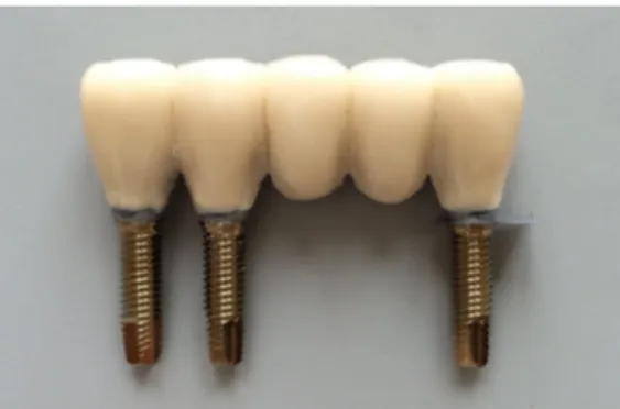
Twenty screw retained five-unit implant-supported FDPs were manufactured on implant level (Nobel Brånemark System RP, Göteborg, Sweden). All frameworks were made in titanium with veneering porcelain. The design and geometry was simplified and standardized for all specimens. Manufacturing of the specimens
A master model was fabricated in plaster (Vel-Mix Stone. Kerr Nordic, Tranås, Sweden) with three implant analogues at a standardized distance that represented position 1, 2 and 5 (figure 1). A prototype for the framework was built up using a resin material (Dura-Lay, Reliance Dental MFG Co, Worth, IL, USA) and wax-up sleeves (Nobel Biocare AB, Göteborg, Sweden) in premolar size on the analogues. The prototype was scanned in a NobelProcera 2G scanner (Nobel BioCare AB, Göteborg, Sweden) and sent for production of twenty identical milled titanium frameworks (NobelProcera Implant Bridge Titanium, Nobel Biocare AB, Göteborg, Sweden). Veneering procelain was applied using a two-piece putty mold (Provil Novo Putty, Heraeus Kulzer GmbH, Hanau, Germany) to achieve reproducibility. The veneering porcelain (GC Initial Ti. GC Europe, Leuven, Belgium) was applied in five layers (1 bonder, 2 opaquer and 2 dentine) according to the manufacturers instruction and fired under vacuum in a furnace (Ivoclar Programat P500. Ivoclar Vivadent AG, Schaan, Liechtenstein). The same dental technician performed all the steps in the process.
Randomization and embedment
The twenty specimens were randomized into a test and control group, with ten samples in each. To achieve a completely passive fit between the implant and FDP, the specimens in the control group were first connected to the analogues (Nobel Brånemark System Groovy Mk III RP 3,75x13mm. Nobel Biocare AB, Göteborg, Sweden) with abutment screws (Abutment Screw Brånemark System RP, Nobel Biocare AB, Göteborg, Sweden) using hand force. The analogues were then fixed to predrilled PMMA blocks with epoxy (EpoFix, Struers A/S, Ballerup, Denmark) that cured for 24 hours. The same procedure was repeated in the test group with the exception that spacers cut from a 150 µm steel sheet were placed between the FDPs and implant- analogues at position 5 (figure 1
and 2).
Figure 1 Specimen attached to analouges with
a steel sheet representing the misfit at position five.
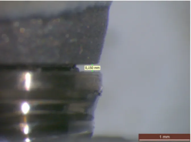
After the embedment the specimens were dismounted and inspected for defects. The spacers were removed from the test group and controlled by a calibrated light microscopy (Wild M3, Wild Heerbrugg, Switzerland) to have a misfit of 150 +/- 5 µm. The measurements were taken on the gap formed at the outer margin between the upper border of the dental implant and the lower boarder of the FDP (figure 3). All the specimens were then remounted to the embedded analogues with a manual torque wrench (Manual Torque Wrench Prosthetic, Nobel Biocare AB, Götebrog, Sweden) to 35 Ncm according to the manufactures recommendations. The FDPs in the test group were deflected to close the misfit. The screw access holes were closed with silicon string (Kuntze & Co AB, Hägersten, Sweden) and dental restorative composite (Tetric Evo Ceram. Ivoclar Vivadent AG, Schaan, Liechtenstein). The same operator performed all the steps in the process.
Cyclic loading test
A cyclic loading machine (MTI Engineering AB, Lund/Pamaco AB, Malmö, Sweden) (Figure 4) was used to assimilate an artificial aging of the restorations. The test was performed at the
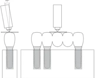
department of prosthodontics, Malmö University. The specimens were submerged in water and mounted at a 10° angle to the force direction (Figure 5). Both groups were subjected to cyclic loading of totally 100 000 cycles at loads between 30 to 300 N. The frequency was 2 Hz and the load was applied by a 2.5 mm stainless steel ball directed to the middle of the occlusal surface at position 3. A thin plastic foil was placed between the indenter and the restoration surface (PE-Baufolie, Probau, Mannheim, Germany) (Figure 6).
Figure 3 Measurement of the misfit through light microscopy.
To record visible cracks and chip-off fractures, a LED white light source (Ronvig Dental Mfg, Daugaard, Denmark) was used to control all the specimens at five occasions: before loading and after 10, 10 000, 50 000 and 100 000 cycles. When a specimen at any occasion presented a chip-off fracture it was excluded from further testing. When a crack was record it was kept in testing to check for further crack propagation and/or chip-off fractures. After completion of the cyclic loading test the composite plugs were removed from the specimens and a retorque meter (Tohnichi digital torque gauge model BTGE-G, Tonichi MFG Co, Tokyo, Japan) was used to control the retorque values for loosening of screws. The same operator performed all the registrations during the process.
Statistical analysis
The difference between the test- and control group regarding occurrence of visible cracks and chip-off fractures at the different intervals was analysed by Fisher’s exact probability test. The difference between test- and control group regarding retorque value was analyzed by independent groups t-test of the means at the different positions. The SPSS software (SPSS 18.0, SPSS Inc, Chicago, IL, USA) was used to perform the calculations. Calculations were made in collaboration with a statistician. Differences were considered statistically significant at p<0, 05.
Figure 6 Specimen mounted in the cyclic loading machine Figur 5 Illustration of the 10° angulation and the
Results
The data and statistical analyses yield the following results. Cracks
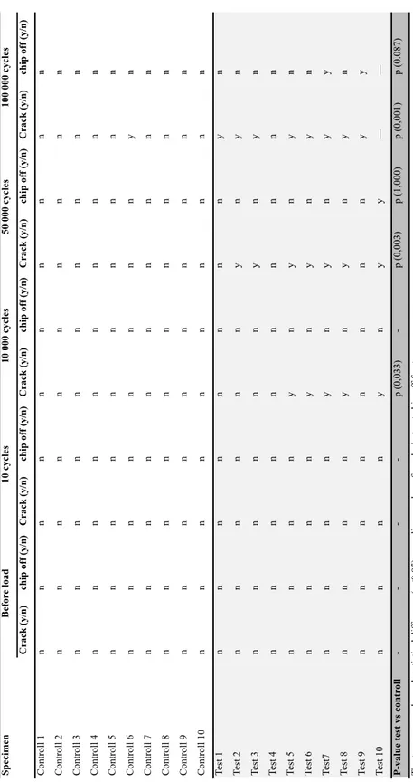
No immediate cracks occurred at the start of cyclic load and the 10-cycle check. Visible cracks within the porcelain veneer occurred significantly more often in the test group compared to the control group: at 10 000 (p <0,033), 50 000 (p <0,003) and 100 000 (p< 0,001) (Figure 7). After 100 000 cycles of loading, nine out of ten FDPs in the test group was presented with visible cracks, compared to one out of ten in the control group. (Table 1)
The location of the cracks differed between test and control group. Most cracks occurred between implant position 2 and the pontic at position 3. Cracks in the test group were also found in various other positions (Figure 8). In one of the test specimens two cracks occurred in position 1 and 5. The only crack observed in the control group was located between the implant position 2 and the pontic at position 3 (Figure 9). (Table 1)
Figure 7 A visible crack in the
porcelain (arrow)
Figure 8 Location of cracks in the test
group. Six out of the ten cracks were observed at the pontic next to implant position 2.
Figur 9 Location of crack in the control
Chip-off fractures
No immediate chip-off fractures occurred at the start of cyclic load and the 10-cycle check. At the visual inspection after 50 000 cycles one specimen in the test group was presented with a chip-off fracture. This specimen was there by excluded from further testing. After 100 000 cycles additional two specimens presented chip-off fractures. In total, three chip-off fractures were recorded in the test group, none in the control group. This difference was not statistically significant (p<0.05) at any control occasion. (Table 1)
S p ec ime n C rac k (y/ n ) ch ip off (y/ n ) C rac k (y/ n ) ch ip off (y/ n ) C rac k (y/ n ) ch ip off (y/ n ) C rac k (y/ n ) ch ip off (y/ n ) C rac k (y/ n ) ch ip off (y/ n ) Cont rol l 1 n n n n n n n n n n Cont rol l 2 n n n n n n n n n n Cont rol l 3 n n n n n n n n n n Cont rol l 4 n n n n n n n n n n Cont rol l 5 n n n n n n n n n n Cont rol l 6 n n n n n n n n y n Cont rol l 7 n n n n n n n n n n Cont rol l 8 n n n n n n n n n n Cont rol l 9 n n n n n n n n n n Cont rol l 10 n n n n n n n n n n Te st 1 n n n n n n n n y n Te st 2 n n n n n n y n y n Te st 3 n n n n n n y n y n Te st 4 n n n n n n n n n n Te st 5 n n n n y n y n y n Te st 6 n n n n y n y n y n Test7 n n n n y n y n y y Te st 8 n n n n y n y n y n Te st 9 n n n n n n n n y y Te st 10 n n n n y n y y — — P -val u e te st vs c on tr ol l -p (0,033) -p (0,003) p (1,000) p (0,001) p (0.087) T he tw o groups s how ed s ta ti st ic al di ffe re nc e (p<0.05) re ga rdi ng num be r of c ra cks but not c hi p-of f fra ct ure s. y=ye s, n=no Be for e l oad 10 c yc le s 10 000 c yc le s 50 000 c yc le s 100 000 c yc le s T ab le 1 Cra cks a nd c hi p of f fra ct ure s
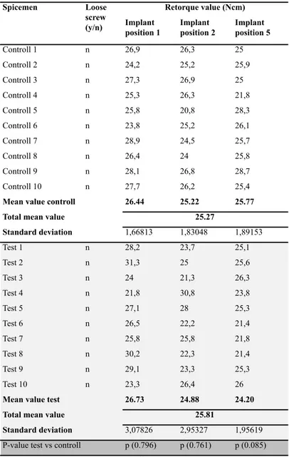
Screw loosening and retorque value
After 100 000 cycles none of the screws in the groups were loose. The difference in mean retorque value between the test and control group was greatest at the position of introduced misfit, position 5. When controlling the retorque values there were no statistical significant differences (p<0.05) neither between the implant positions nor the groups. (Table 2)
Spicemen Implant position 1 Implant position 2 Implant position 5 Controll 1 n 26,9 26,3 25 Controll 2 n 24,2 25,2 25,9 Controll 3 n 27,3 26,9 25 Controll 4 n 25,3 26,3 21,8 Controll 5 n 25,8 20,8 28,3 Controll 6 n 23,8 25,2 26,1 Controll 7 n 28,9 24,5 25,7 Controll 8 n 26,4 24 25,8 Controll 9 n 28,1 26,8 28,7 Controll 10 n 27,7 26,2 25,4
Mean value controll 26.44 25.22 25.77
Total mean value
Standard deviation 1,66813 1,83048 1,89153 Test 1 n 28,2 23,7 25,1 Test 2 n 31,3 25 25,6 Test 3 n 24 21,3 26,3 Test 4 n 21,8 30,8 23,8 Test 5 n 27,1 28 25,3 Test 6 n 26,5 22,2 21,4 Test 7 n 25,8 25,8 21,8 Test 8 n 30,2 22,3 21,4 Test 9 n 29,1 23,3 25,3 Test 10 n 23,3 26,4 26
Mean value test 26.73 24.88 24.20
Total mean value
Standard deviation 3,07826 2,95327 1,95619
P-value test vs controll p (0.796) p (0.761) p (0.085)
Loose screw (y/n)
Table 2 Screwloosening and retorque value after 100 000 cycles
Retorque value (Ncm)
25.27
25.81
The two groups showed no statistical difference (p<0.05) in screw loosening when comparing the different implant positions. y=yes, n=no
Discussion
The hypothesis was confirmed regarding cracks since the specimens with misfit had a significantly higher rate of cracks compared to the control group. There was also a higher rate of chip-off fractures in the test group, but this difference was not statistically significant. No difference in screw loosening was observed between the groups.
Discussion of the material and method
An in vivo study is an experiment or observation performed on living organisms, while an in vitro study is made in an artificial environment or in a not living body (39). In this in vitro it was of great importance to make the environment as similar as possible to that of the oral cavity. The oral environment and the stresses created during function are complex, which makes it demanding and difficult to simulate. It´s also important to bear in mind that an in vitro study will never completely mimic the clinical situation, and it is not possible to directly apply the results to the clinical
situation. (40) Above all, in vitro tests are important to predict the mechanical behaviour before clinical tests are performed.
As dental implants are subjected to functional loads in vivo it is important to use an artificial aging test in terms of cyclic loading to simulate the loads and to be able to evaluate the behaviour of the restorations (41). It is the cyclic loading during mastication rather than short term static maximum loads that is most detrimental and the most common cause of clinical failure (42). No consensus exists regarding how an aging procedure should be performed (43).One regularly cited study claims that as much as 800 000 chewing cycles may be performed per year. The study did however not perform any measurements; instead a provisory survey was made among dental students and assistants on the university. (44) The validity and reliability of those results may therefore be unreliable. If this estimate is correct it would mean that 100 000 cycles, as used in this study, is equivalent to a couple of months of chewing. Probably more cycles should be needed to evaluate the materials long-term behaviour, but since this is a pilot study and due to the results seen already at 100 000 cycles, the cyclic load test was terminated at this point.
The cyclic load hade a frequency of 2 Hz, as recommended by the ISO (45).This is comparable to one study that found that the mean chewing frequency in vivo was 1.2 Hz (44). Regarding loads during normal function there is no accepted consensus concerning how they should be replicated in
vitro (43). The maximal bite force depends on various factors including muscles strength,
periodontal and dental lesions, the method of measuring, sex, age group, dentures wearers vs. natural teeth, position in the dental arch and presence or absence of clinical symptoms of
dysfunction. One in vivo study observed that the maximal bite force in the molar region was 102 to 744 N compared to 10 to 449 N in the incisor area. (46) A review that summarized several studies that evaluated bite forces, showed that forces during mastication and swallowing where
approximately 5 to 364 N depending hardness and texture of the food. Maximal forces during clenching efforts were approximately 216 to 890 N. (42) Regarding osseointegrated implants a study by Carlsson et al. showed that bite forces in patients with implants can be comparable to forces generated in the natural dentitionwhile another study found that the forces sometimes exceed 300 N (47, 48).Due to the lack of consensus regarding loads a load between 30 to 300 N was chosen in this study since it is assumed to be within the range of normal function (49). To avoid local force peaks, a thin plastic foil was additionally inserted between the steel ball and the cusps at position 3.
The occlusal contacts in vivo consist of wear facets in dimensions of approximately 0.5 to 3.0 mm in diameter and not as a point contact as in this cyclic loading test seen in this study. This makes the force in the cyclic loading test concentrated to a smaller area, creating a greater pressure on the bridge in vitro, compared to in the clinical situation. A larger diameter of the steel ball (0,04 m to 1 m) has been proposed to better mimic the pressure that arises on the abrasion-facets. (42) However, a larger diameter of the steel ball is more difficult to place in the fossa, which creates horizontal forces on the cusps instead and does not reflect the clinical situation either. (50)
A 30° angulation of the forces is recommended by the ISO to represent a worst-case scenario (45). Such angulation is not clinically relevant for the posterior dentition though (51). If this angulation should have been used, it would probably overemphasize the risks of complications and
micromorphological changes. In the cyclic loading test of this study, a 10° inclination of the steel ball was used to create both compressive and tensile forces, as well as a small sliding movement. This is more truthful to the complex stresses seen in the clinical situation.(50) One study has shown that the lack of fine motor control in implant-supported restorations may lead to chewing forces applied in the wrong direction (14). For this reason, an angle of more than 10° is possibly a better imitation of reality. However, one must keep in mind how much of the dentition that consists of implant-supported restorations. If only a small FDP is present, probably the rest of the dentition can compensate with its’ fine motor control and perhaps the change in force direction is not particularly significant.
To simulate the oral environment the specimens were submerged in water. This aqueous
environment is important to recreate in the cycling loading test due to the subcritical crack growth phenomena of ceramics, a water-assisted breakage of the metal-oxide bonds at the crack tip under applied stress. This fatigue reduces the fracture strength compared to the initial strength within the material compared to when not submerged in water, which is important for obtaining realistic results. (52)
To our knowledge, no previous studies have been performed in this area before which made it impossible to perform a power analysis. Ten specimens in each group were chosen to evaluate the sample size, a number that turned out to be sufficient. Due previous studies have shown a higher frequency of chip-off fractures on supported FDPs (8,8 % in 5 years) compared to implant-supported single crowns (3,5 % in 5 years), a 5-unit FDP was chosen in this study (26). May be the higher prevalence of chip-off fractures can be explained by a greater risk for misfit with more units. It may be of interest to evaluate the misfit’s impact on chip-off fractures on even larger restorations. The framework was manufactured in titanium since this is a material with poor bonding to porcelain compared to conventional metal-ceramic restorations (53).It should not be forgotten that just one specific implant system was included in this study (Nobel implant system). Conclusions about the results may not be fully representable regarding other systems. Since the results are significant regarding cracks it would have been of interest to research other materials and implant systems as well.
To ensure an in vitro set up which mimic the clinical situation, the crowns were anatomically shaped. A putty mold technique was used to guide the dental technician and to assure
reproducibility in dimension and design of the veneering porcelain. The PMMA embedment material has a modulus of elasticity within the range of cancellous bone and can thereby support implants in fatigue tests, simulating in vivo conditions. (47)
Dimensional measurements were of interest in this study as a misfit was created between the implant and the FDP. This measuring technique includes three methods: Microscope,
photogrammetric technique and coordinate measuring machine (CMM).In this study, a light microscope was used to control the gap of 150 µm in the test group after the steel sheet was removed. Light microscope is a relatively simple technique that requires a standardization to achieve comparable results. A disadvantage of this technique is that only the vertical gap can be measured, which may have affected our results since misfits in the other dimensions cannot be excluded. The method has also a variable accuracy. To achieve good accuracy, repeatability and ability to measure in three dimensions, photographic- and CMMs must be used, but these are expensice techniques. (18)
Since there is no exact definition of misfit, a gap of 150 µm was chosen to represent a misfit in this study. This is the biggest value suggested by authors to define a passive fit. The size of this gap was also obvious when visually inspected. As an absolute passive fit is considered to not be achievable in a biomechanical perspective, one can ask what a clinically acceptable gap actually is. This question is relevant since restorations without absolute passive fit in vitro have shown clinically acceptable results. By this reason, many authors have discussed against the significance of a passive fit. (18) A slight misfit can probably be accepted unless it affects the outcome. It may be of interest to investigate different sizes of misfit and to determine which size that is required for causing chip-off and screw loosening in vitro. Possibly this can eventually get us closer to the definition of what a clinically acceptable passive fit is.
The specimens in the control group were first connected to the analogues and then fixed to the PMMA blocks with epoxy that cured for 24 hours to achieve a passive fit. However, a limitation of this study is that the control group was not controlled for passive fit before the artificial aging process began. If the specimens in the control group had been checked, a totally passive fit would probably not be achievable, as previously discussed. Furthermore, a value would have had to be chosen to represent a passive fit. Most likely, the measured gap would fall within the context of this value. If this method is used in further studies it is suggested that this step should be added for increased evidence.
Discussions of the results
A pilot study is a small-scale test, preformed as a first step in evaluating whether a method can be used in a larger scale. The result of the pilot study gives information regarding the feasibility and serves as a guide to identify problems that should be changed before a larger study is preformed. (54)
The results showed a significant difference in crack-growth when comparing the test- and control group with a predominance of cracks in the test group after 10 000, 50 000 and 100 000 cycles. The differences were clearly significant already after 50 000 cycles. This is in accordance with a
statement that ceramic failure is predicted to occur mostly within the first days after insertion and should therefore be detected at early stages of cyclic loading (42). However, it cannot be ruled out that the prevalence of fractures within the veneer might differ with increasing number of cycles, as a fracture in the control group only occurred at the end of the test. In future studies, it would have been of interest to increase the number of cycles performed. When closing a misfit, bending-, tensile- and compressive forces arise in the complex (18, 21, 22, 24, 25). These stresses may explain the significantly higher degree of cracks in the test group compared to the control group. One must not forget that crack growth can lead to catastrophic failure. (55)Cracksarise due to tensile stress and if the cracks propagate they may lead to chip-off fractures (56). In the present study three chip-off fractures occurred in the test group and none in the control group, but the
differences were not significant. A possible explanation could be that results regarding cracks were seen already at 100 000 cycles, corresponding approximately 6 weeks in vivo (44). This is not enough cycles to be able to draw any conclusions about the material's long-term behaviour. If further research is preformed using this method, more cycles may result in a significance regarding chip-off fractures as well. However, since this is a pilot study, conclusions from these results cannot be drawn. Nevertheless, it gives us guidance about the misfit’s potential impaction on success and that the method with some modifications can be used in further researches.
In the present study no screws were loose when controlled after 100 000 cycles. This is in line with the results in a study by El-Homsi et al, which showed that screw loosening occurred first when the loads exceeded 300 N (47). Berglundh et al demonstrated that screw loosening is a major problem when it comes to technical complications in implant-supported restorations (57). In this study, no differences were observed regarding retorque value when comparing the test and control group. In contrast, other studies that evaluate the effect of misfit on screw loosening have observed detorque after cycling loading (33,34).One explanation to why no differences were observed in this study may be that the specimens were subjected to 100 000 cycles only. Possibly, the size of the gap is another factor that can influence the degree of screw loosening. If further larger studies are made based on this pilot study, it is of interest to investigate whether detorque occurs in accordance with earlier studies (33,34).
The population is moving towards having a higher average life expectancy. The patient expects both a functional and aesthetical capacity of their implants for many years. Higher demands on the success rate of prosthetic restorations are therefore required. Implant treatment has become a more common treatment option, but has a relatively high frequency of complications. The complications often creates unnecessary suffering for the patient and as the complications often occur within the warranty period of two years, this is a economical issue for the clinic as well. (58) If the warranty has expired and the cost is too big, this might lead to reduced aesthetics and function as well as an impact on the patient’s psychosocial condition and reduced quality of life. If one can discover the reasons for chip-off fractures the complication rate may be reduced through targeted actions. For example: Strict control of every step in the manufacturing process, development of the processing procedure, a reduced number of steps in the manufacturing process and development of the use of CAD/CAM (18). From a socioeconomic perspective, a reduced complication rate would result in benefits for the patient, clinic and community itself.
Conclusion
Since this is a pilot study, conclusions from the results cannot be drawn. Nevertheless, within the limitations of this in-vitro study, the results indicate that the presence of a misfit between the metal-ceramic restoration and implant may have an impact on success. It is suggested that the veneering porcelain may have an increased risk of cracking and/or chip-off fractures with a present misfit. Further studies are needed to confirm these findings. If the method of this pilot study is used in further research it is of interest to investigate the outcome when using increased periods of cyclic load, different gap sizes defining a misfit and different types of restorations and materials.
References
1. Nilner K, edt, Karlsson S, edt, Dahl BLe. A Textbook of Fixed Prosthodontics : The Scandinavian Approach. Stockholm: Gothia fortbildning, 2013 (Slovenien); 2013. 372-379.
2. Phillips RW, Anusavice KJ, Shen C, Rawls HR. Phillips' Science of Dental Materials. St. Louis, Mo. : Elsevier/Saunders, c2013; 12th ed, 2013. 34, 123, 367-384, 411, 420, 439-445.
3. Adell R, Lekholm U, Rockler B, Branemark PI. A 15-year study of osseointegrated implants in the treatment of the edentulous jaw. Int J Oral Surg 1981; 10: 387-416.
4. Bidra AS, Rungruanganunt P. Clinical outcomes of implant abutments in the anterior region: a systematic review. J Esthet Restor Dent 2013; 25: 159-176.
5. Sailer I, Philipp A, Zembic A, Pjetursson BE, Hammerle CH, Zwahlen M. A systematic review of the performance of ceramic and metal implant abutments supporting fixed implant
reconstructions. Clin Oral Implants Res 2009; 20 Suppl 4: 4-31.
6. Lewis MB, Klineberg I. Prosthodontic considerations designed to optimize outcomes for single-tooth implants. A review of the literature. Aust Dent J 2011; 56: 181-192.
7. Schittek Janda, Martin, aut edt, Mattheos Nae, Larsson C, aut, Ekenbäck J, aut. Implantat : Att Förebygga, Diagnostisera Och Hantera Komplikationer. Stockholm : Gothia fortbildning, 2014 (Slovenien); 1. uppl, 2014. 13-19, 83-91, 111-113.
8. Zarone F, Russo S, Sorrentino R. From porcelain-fused-to-metal to zirconia: clinical and experimental considerations. Dent Mater 2011; 27: 83-96.
9. Wang RR, Fenton A. Titanium for prosthodontic applications: a review of the literature. Quintessence Int 1996; 27: 401-408.
10. Teigen K, Jokstad A. Dental implant suprastructures using cobalt-chromium alloy compared with gold alloy framework veneered with ceramic or acrylic resin: a retrospective cohort study up to 18 years. Clin Oral Implants Res 2012; 23: 853-860.
11. Anusavice KJ. Standardizing failure, success, and survival decisions in clinical studies of ceramic and metal-ceramic fixed dental prostheses. Dent Mater 2012; 28: 102-111.
12. Larsson C. Zirconium dioxide based dental restorations: studies on clinical survival and fracture behavior. Swedish Dental Journal 2011, 213: 9-84.
13. Beertsen W, McCulloch CA, Sodek J. The periodontal ligament: a unique, multifunctional connective tissue. Periodontol 2000 1997; 13: 20-40.
14. Trulsson M, van der Bilt A, Carlsson GE, Gotfredsen K, Larsson P, Muller F et al. From brain to bridge: masticatory function and dental implants. J Oral Rehabil 2012; 39: 858-877.
15. Lang NP, Pjetursson BE, Tan K, Bragger U, Egger M, Zwahlen M. A systematic review of the survival and complication rates of fixed partial dentures (FPDs) after an observation period of at
least 5 years. II. Combined tooth--implant-supported FPDs. Clin Oral Implants Res 2004; 15: 643-653.
16. Klineberg I, Murray G. Osseoperception: sensory function and proprioception. Adv Dent Res 1999; 13: 120-129.
17. Enkling N, Utz KH, Bayer S, Stern RM. Osseoperception: active tactile sensibility of osseointegrated dental implants. Int J Oral Maxillofac Implants 2010; 25: 1159-1167. 18. Abduo J, Bennani V, Waddell N, Lyons K, Swain M. Assessing the fit of implant fixed prostheses: a critical review. Int J Oral Maxillofac Implants 2010; 25: 506-515.
19. Cho GC, Chee WW. Apparent intrusion of natural teeth under an implant-supported prosthesis: a clinical report. J Prosthet Dent 1992; 68: 3-5.
20. Garcia LT, Oesterle LJ. Natural tooth intrusion phenomenon with implants: a survey. Int J Oral Maxillofac Implants 1998; 13: 227-231.
21. Sahin S, Cehreli MC. The significance of passive framework fit in implant prosthodontics: current status. Implant Dent 2001; 10: 85-92.
22. Karl M, Winter W, Taylor TD, Heckmann SM. In vitro study on passive fit in implant-supported 5-unit fixed partial dentures. Int J Oral Maxillofac Implants 2004; 19: 30-37.
23. Jemt T. Failures and complications in 391 consecutively inserted fixed prostheses supported by Branemark implants in edentulous jaws: a study of treatment from the time of prosthesis placement to the first annual checkup. Int J Oral Maxillofac Implants 1991; 6: 270-276.
24. Watanabe F, Uno I, Hata Y, Neuendorff G, Kirsch A. Analysis of stress distribution in a screw-retained implant prosthesis. Int J Oral Maxillofac Implants 2000; 15: 209-218.
25. Clelland NL, Papazoglou E, Carr AB, Gilat A. Comparison of strains transferred to a bone simulant among implant overdenture bars with various levels of misfit. J Prosthodont 1995; 4: 243-250.
26. Pjetursson BE, Bragger U, Lang NP, Zwahlen M. Comparison of survival and complication rates of tooth-supported fixed dental prostheses (FDPs) and implant-supported FDPs and single crowns (SCs). Clin Oral Implants Res 2007; 18 Suppl 3: 97-113.
27. Proceedings of the 3rd EAO Consensus Conference, 15-18 February 2012, Pfaffikon, Schwyz, Switzerland. Clin Oral Implants Res 2012; 23 Suppl 6: 1-241.
28. Karl M, Graef F, Wichmann MG, Heckmann SM. The effect of load cycling on metal ceramic screw-retained implant restorations with unrestored and restored screw access holes. J Prosthet Dent 2008; 99: 19-24.
29. Pjetursson BE, Thoma D, Jung R, Zwahlen M, Zembic A. A systematic review of the survival and complication rates of implant-supported fixed dental prostheses (FDPs) after a mean
30. Kunavisarut C, Lang LA, Stoner BR, Felton DA. Finite element analysis on dental implant-supported prostheses without passive fit. J Prosthodont 2002; 11: 30-40.
31. Jemt T. In vivo measurements of precision of fit involving implant-supported prostheses in the edentulous jaw. Int J Oral Maxillofac Implants 1996; 11: 151-158.
32. Cibirka RM, Nelson SK, Lang BR, Rueggeberg FA. Examination of the implant-abutment interface after fatigue testing. J Prosthet Dent 2001; 85: 268-275.
33. Farina AP, Spazzin AO, Pantoja JM, Consani RL, Mesquita MF. An in vitro comparison of joint stability of implant-supported fixed prosthetic suprastructures retained with different prosthetic screws and levels of fit under masticatory simulation conditions. Int J Oral Maxillofac Implants 2012; 27: 833-838.
34. al-Turki LE, Chai J, Lautenschlager EP, Hutten MC. Changes in prosthetic screw stability because of misfit of implant-supported prostheses. Int J Prosthodont 2002; 15: 38-42.
35. Bhering CL, Marques Ida S, Takahashi JM, Barao VA, Consani RL, Mesquita MF. Fit and Stability of Screw-Retained Implant-Supported Frameworks Under Masticatory Simulation: Influence of Cylinder Type. J Prosthodont 2016; 25: 459-465.
36. Swain MV. Unstable cracking (chipping) of veneering porcelain on all-ceramic dental crowns and fixed partial dentures. Acta Biomater 2009; 5: 1668-1677.
37. Ozcan M. Fracture reasons in ceramic-fused-to-metal restorations. J Oral Rehabil 2003; 30: 265-269.
38. Klineberg IJ, Trulsson M, Murray GM. Occlusion on implants - is there a problem? J Oral Rehabil 2012; 39: 522-537.
39. Nationalencyklopedin AB. In vivo/In vitro [internet]. Malmö: Nationalencyklopedin; . http://www.ne.se.proxy.mah.se/uppslagsverk/encyklopedi/lång/in-vivo. Updated 2017-02-13. Accessed 02-13, 2017.
40. Anusavice KJ, Kakar K, Ferree N. Which mechanical and physical testing methods are relevant for predicting the clinical performance of ceramic-based dental prostheses? Clin Oral Implants Res 2007; 18 Suppl 3: 218-231.
41. Dittmer MP, Nensa M, Stiesch M, Kohorst P. Load-bearing capacity of screw-retained CAD/CAM-produced titanium implant frameworks (I-Bridge(R)2) before and after cyclic mechanical loading. J Appl Oral Sci 2013; 21: 307-313.
42. Kelly JR. Clinically relevant approach to failure testing of all-ceramic restorations. J Prosthet Dent 1999; 81: 652-661.
43. Kelly JR, Benetti P, Rungruanganunt P, Bona AD. The slippery slope: critical perspectives on in vitro research methodologies. Dent Mater 2012; 28: 41-51.
44. Rosentritt M, Behr M, Gebhard R, Handel G. Influence of stress simulation parameters on the fracture strength of all-ceramic fixed-partial dentures. Dent Mater 2006; 22: 176-182.
45. the International Organization for Standardization. ISO 14801:2007 Dentistry -- Implants -- Dynamic fatigue test for endoosseous dental implants [Internet]. Geneva, Switzerland: the International Organization for standardization;
http://www.iso.org/iso/home/store/catalogue_tc/catalogue_detail.htm?csnumber=41034. Updated 2016-10-24. Accessed 02/06, 2017.
46. Helkimo E, Carlsson GE, Helkimo M. Bite force and state of dentition. Acta Odontol Scand 1977; 35: 297-303.
47. El-Homsi F, Lockowandt P, Linden LA. Simulating periodontal effects in dental
osseointegrated implants: effect of an intramobile damping element on the fatigue strength of dental implants--an in vitro test method. Quintessence Int 2004; 35: 449-455.
48. Haraldson T, Carlsson GE. Bite force and oral function in patients with osseointegrated oral implants. Scand J Dent Res 1977; 85: 200-208.
49. Bates JF, Stafford GD, Harrison A. Masticatory function-a review of the literature: (II) Speed of movement of the mandible, rate of chewing and forces developed in chewing. J Oral Rehabil 1975; 2: 349-361.
50. Nordahl N, Vult von Steyern P, Larsson C. Fracture strength of ceramic monolithic crown systems of different thickness. J Oral Sci 2015; 57: 255-261.
51. Andrews LF. The six keys to normal occlusion. Am J Orthod 1972; 62: 296-309.
52. Studart AR, Filser F, Kocher P, Luthy H, Gauckler LJ. Cyclic fatigue in water of veneer-framework composites for all-ceramic dental bridges. Dent Mater 2007; 23: 177-185.
53. Aslan MA, Ural C, Arici S. Investigation of the effect of titanium alloy surface coating with different techniques on titanium-porcelain bonding. J Prosthet Dent 2016; 115: 115-122.
54. Leon AC, Davis LL, Kraemer HC. The role and interpretation of pilot studies in clinical research. J Psychiatr Res 2011; 45: 626-629.
55. Zhang Y, Lawn B. Long-term strength of ceramics for biomedical applications. J Biomed Mater Res B Appl Biomater 2004; 69: 166-172.
56. Liu Y, Liu G, Wang Y, Shen JZ, Feng H. Failure modes and fracture origins of porcelain veneers on bilayer dental crowns. Int J Prosthodont 2014; 27: 147-150.
57. Berglundh T, Persson L, Klinge B. A systematic review of the incidence of biological and technical complications in implant dentistry reported in prospective longitudinal studies of at least 5 years. J Clin Periodontol 2002; 29 Suppl 3: 197-212; discussion 232-3.
58. Larsson C, Vult von Steyern P, Nilner K. A prospective study of implant-supported full-arch yttria-stabilized tetragonal zirconia polycrystal mandibular fixed dental prostheses: three-year results. Int J Prosthodont 2010; 23: 364-369.