[1] –
Individual Stress Diagnosis
from Skin Conductance
sensor signals
Author: Theodore Belogiannis Mälardalen University, IDT Department Supervisor: Shahina Begum and Mobyen Uddin Ahmed Examiner: Peter Funk
School of Innovation, Design and Engineering
MASTER THESIS IN
INTELLIGENT EMBEDDED SYSTEMS
[2]
Abstract
Human stress has become a serious problem affecting people’s life. The current state of sensor technology allows developing systems measuring physical symptoms reflecting people’s stress level. However, the detection of stressful events using the skin conductance (SC) and finger temperature (FT) data is a challenging task due to varieties of patterns in the data. Also each person handles stress in a different way.
A big part of the thesis work is to compare the proximity of the results from FT sensor and SC sensor data using two artificial intelligence techniques (AI): neural networks (NN) and case base reasoning (CBR). More precise the features extracted from the data are: FT slope and SC slope that detects the angle of change of the signal and skin conductance response (SCR) which is the change in SC within a short period of time. These feature data are stored in a database and matched against old cases in the CBR case library. In the NN case, weights are automatically been assigned to each feature to produce a result. These three features are applied separately to the CBR and to the NN. The results from the combined experiments are expected to derive to the most efficient “set” (sensor/features/A.I. technique) that automatically produce an answer closest to that of a clinician’s expert diagnosis.
The current thesis experimental workflow proved that using both CBR and NN with SC and FT slope features can give up to 83% successful results. Unfortunately the SCR features didn’t give the same results and it is suggested as a future work to complete the algorithm of feature extraction. A big contribution of this thesis work is that the FT & SC slope algorithm shows a promising performance on both CBR and NN. Another contribution is on the SCR feature extraction where the biggest part of the work has been done using Matlab code.
[3]
Contents
Abstract ... 2 Contents ... 3 1. Background ... 4 1.1 Case-based reasoning ... 4 1.2 Neural Networks ... 5 2. Related work ... 7 3. Experiments ... 103.1 Problem Formulation and Analysis ... 10
3.2 SC Feature extraction ... 11
SCR Filtering – Normalization ... 12
SCR Amplitude and Duration ... 13
SCR Features Used ... 14
3.3 FT using Neural Network ... 15
FT slope features with Pattern recognition tool. ... 16
FT slope features using NN Fitting Tool ... 18
4. Results ... 19
4.1 The Features on CBR platforms against expert classification ... 19
4.2 Neural Network Pattern Recognition and Features comparison ... 23
5. Conclusion – Future Work ... 25
Acknowledgement ... 25
Appendices ... 26
AppendixA ... 26
SCR feature extraction Matlab code ... 26
Appendix B ... 28
SCR features results ... 28
Appendix C ... 31
Pattern Recognition with FT feature Matlab code ... 31
Appendix D ... 32
Fitting tool with FT feature Matlab code ... 32
Appendix E ... 33
Pattern Recognition Matlab code ... 33
References ... 34
[4]
1. Background
The current thesis work researches the area of humans stress detection from physiological sensor signals. Artificial intelligence is the proposed method of classifying humans stress because it is based on existing knowledge from an expert to produce a reasonable result. In this chapter the basic theory of CBR and NN will be presented because one important part of this thesis is to compare those two artificial intelligence techniques in the area of stress detection.
1.1 Case-based reasoning
Case-based reasoning (CBR) is one of the major components of the current project. In most literatures CBR is defined as the problem-solving paradigm where past experiences are used to guide problem solving. For example, in fixing a bulb that would not light up a person may recall other similar cases. Based on the past experience he may recall that the electric power needs to be checked, the bulb could have burned out or there may be some other internal electrical problem. In CBR, cases similar to the current problem are retrieved from the case memory, and the best match is selected from those retrieved and adapted to fit the current problem based on the differences between the previous and current cases.
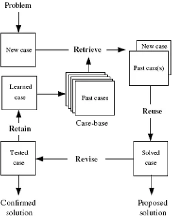
At the highest level of generality, four processes: Retrieve, Reuse, Revise and Retain may describe a general CBR cycle. These processes are discussed in more details in the following paragraphs:
1- Retrieve the most similar case or cases
2- Reuse the information and knowledge in that case to solve the problem 3- Revise the proposed solution
4- Retain the parts of this experience likely to be useful for future problem
Solving a new problem requires: retrieving one or more previously experienced cases, reusing the case in one way or another, revising the solution based on reusing a previous case, and retaining the new experience by incorporating it into the existing knowledge-base (case-base). Each one of these four processes involves a number of more specific steps, as illustrated in Figure 1.1.
[5]
Figure 1.1 The CBR cycle
At the top of Figure 1.1 an initial description of a problem defines a new case. This new case is used to retrieve a case from the case base. Through reuse the retrieved case is combined with the new case into a solved case, i.e. a proposed solution to the initial problem. This solution is tested for success - through the revise process -, e.g. by being evaluated by a specialist or applied to the real world environment (clinic or hospital), and repaired if failed. During retain process, useful experience is retained for future reuse, and the case base is updated by alteration of some existing cases or by a new learned case. The CBR general knowledge is placed in the middle of cycle and its support may range from very weak (or none) to very strong. [5]
In the current thesis two CBR software platforms were used. One is the Fuzzy CBR developed by MDH University and the myCBR an open-source tool developed by DFKI [10]. Both will be further discussed in the experiment chapter.
1.2 Neural Networks
Artificial neural networks (ANNs) are biologically inspired structures of computational elements called neurons. Figure 1.2 shows a single neuron which receives an input value which is thresholded by some function, in this case a sigmoid function. The network functionality is determined by the overall architecture and the type of neurons employed.
[6]
Figure 1.2 A single neuron receives an input multiplied by the weight for that connection, applies some function, and generates an output. Depending on the difference between the desired output and the actual output, the error is propagated back through the network to adjust the weight for that connection, so that through the learning process the weights learn
a model of the desired function which maps inputs to outputs.[6]
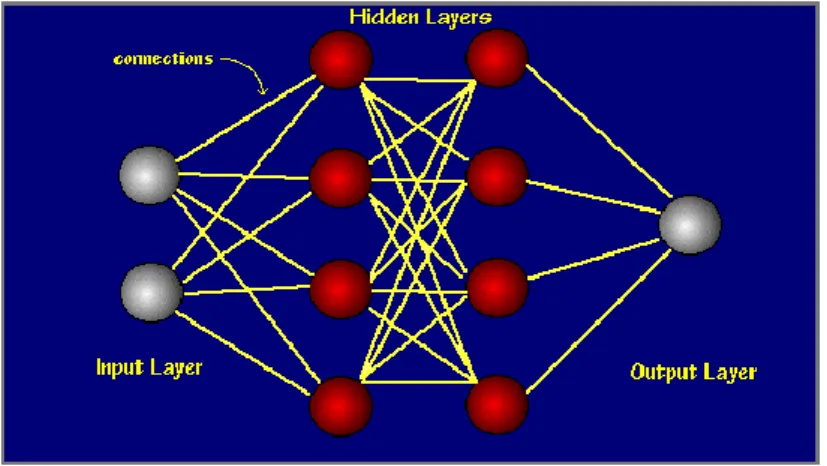
In Figure 1.3 several neurons connected together are shown. Between each two neurons a weight exists which is altered throughout the ‘training’ period. Initial predictions are random (random weights). The network learns by propagating the prediction error backwards through the net, to modify the weights (back propagation).
Figure 1.3. A neural network consists of different layers of neurons connected together. The first layer represents the input features, and the output layer represents the desired class
values.[6]
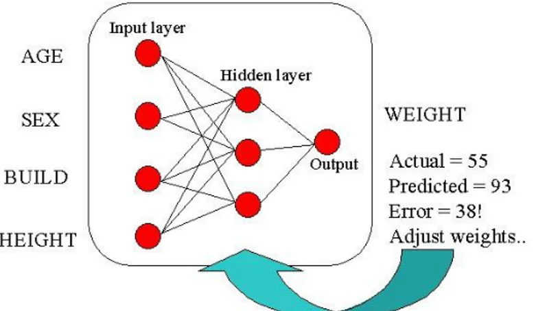
A model is constructed from the data. Because of the architecture employed the model can be non-linear instead of normal linear classifiers. Figure 1.4 shows a network with four input features which have a complex non-linear relationship to the output variable. Whatever the relationship is, given enough training examples, or previously classified cases, the network will model the best mapping function. In this figure the predicted value of 93 given the
[7]
current state of network weights, and the error value is 38. This would be then back propagated through the network to alter the weights to minimize this error. [6]
Figure 1.4. Learning a neural network to predict a person’s weight based upon their age, sex, build and height.
ANNs can be used for association/classification (diagnosis), or regression (prediction). During this thesis workflow the ANN software platform used for diagnosis the stress level is Matlab/Simulink and will be presented in the experiment chapter.
2. Related work
In this chapter some interesting projects will be shown which are dealing with stress detection from SC signals.
The aspect of measurement Electro Dermal Activity (EDA) is done in [9]. The term SC applies to the phenomena of exosomatic measurement of the electrical properties of the skin when external voltage is applied. SC is measured in “Siemens”. When measuring SC two principals are important. Skin Conductance Level (SCL) related to the certain amount of continuity over time (tonic value) and Skin Conductance Response (SCR) which stands for the change in SC within a short period of time as a reaction toward a discrete stimulus (phase value). Studies have shown that SCR is a good measure of stress, anxiety, fear and anger. Another phenomenon is the non-specific SCR fluctuations (NS.SCR) that occur spontaneously without any external stimulus. NS.SCR has the same or a very similar shape as specific SCR. SCR can be characterized by four parameters: Amplitude (SCR amp), Latency of response onset (SCR lat), Rise time of the response peak (SCR ris.t), and the half time of the recovery time (SCR rec.tc) as shown in figure 2.1.
[8] Figure 2.1
Schematic Skin Conductance Response (SCR) to a hypothetical stimulus.[9]
Possible electrode sides are the feet and the palms. When hands used, usually the non-dominant is preferred. Possible sites on the palm are the medial phalanx or the thenar and hypothenar eminences. Figure 2.2.
Figure 2.2 Palmar Electrode Sides[9]
For the signal recording the proposed way is by applying constant dc voltage of 0,5V to the two electrodes and 16 bit resolution (or higher) for the ADC conversion. Off line methods can later be used to split the signal into the SCR and SCL values. Sampling frequency of 15-20 Hz is sufficient and the use of LPF at 5 Hz is essential to filter out noise.
Ideally, an electrode with double-sided adhesive collar is required together with an electrode paste and at an environment of 24-26 Celsius and 50% humidity. Also movements should be avoided. An important research has been done at [4] that shows the signal behavior when the sensor is not tight enough, or when some disturbance occur, if the subject is doing exercise or when sensor is not properly attached. (See figure 2.3).
[9] Figure 2.3
Change of signal due to factors other than stress
For gathering the above signals the subject was having the sensor attached as a clock watch. It is obvious that sensors embodied in car’s steering wheel or even on the gear lever will produce signals difficult to decode. Possible solution for this, is good preprocessing and the use of a second or more external stress sensor signals to participate to the systems output. Finally the SCR shape in stimulus, as shown in figure 2.1, pushed researchers to use the corresponding detection technique.
For example the research in [7] uses the Hanning window to smooth the signal and pattern recognition with Fisher Projection Matrix and Sequential Floating feature selection k-NN for stress detection. The system monitors HR, SC and respiration.
In [4] they use median filter and SAX discretisation. They use a training window of maximum size 100 and detection mechanism in time series with two methods: Cumulative Sum as a statistical model which monitors mean SC values and gives alarm when it deviates far from normal behavior and NN with auto regression. They experiment on the FIT regression model and ADWIN model. Their system use only SC and shown that it is not enough for stress diagnosis.
The article in [8] presents the use of the First Absolute Difference (FAD) from both SCL and SCR and the Bayesian NN for pattern recognition. Their system comprised of HR, SC and driving habits.
The work presented by [2] presents a study of stress detection only based on Finger Temperature (FT), together with Fuzzy Logic and Case-Based Reasoning.
Other approaches have been proposed, based on different techniques like
Support Vector Machines (SVM), ANOVA Analysis, Linear Discriminant Analysis (LDA), Nearest Class Center (NCC), Triggs’ Tracking Variable(TTV). Most use Matlab for evaluation.
[10]
3. Experiments
3.1 Problem Formulation and Analysis
The project’s practical work is summarized in the following steps. Extract SC features from sensor signals.
Apply FT slope features to NN and CBR and compare the results. Apply SC slope features to NN and CBR and compare the results.
Apply the extracted SC features to NN and CBR and compare the results.
The FT and SC slope features are produced by the Fuzzy CBR platform (see next chapter). The FT slope features are produced from detection of the angle of change of the waveform and it is the proposed method for stress detection. The SC slope features have never been used before for stress detection and its part of this project to find its suitability. For the SC feature extraction the proposed method of SCR detection is used as studies has shown its suitability in stress detection.
The remaining of this chapter is divided into the work done for feature extraction from the SC signal and the experiments done on NN fitting tool and pattern recognition tool. The Fuzzy CBR and MyCBR platforms were used unchanged so will only be discussed in the results chapter.
[11] 3.2 SC Feature extraction
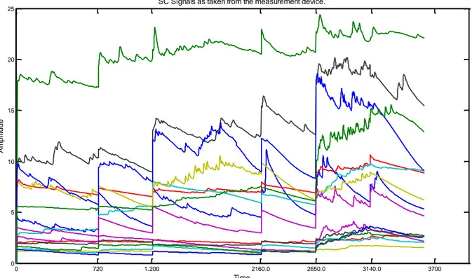
For the purpose of feature extraction from the SC signal, Matlab where used. The experiments were done from signal data measurements from 18 subjects as gathered from the University’s A.I. research group in conjunction with Volvo Co as a part of another project. “Figure 3.1” shows the original 18 signals as taken from the SC sensor measuring device. The first step is to remove the noise. As stated in [9] the use of LPF at 5 Hz is essential to filter out the noise. Appendix A shows the actual Matlab code with the corresponding comments.
Figure 3.1.Original signals as captured from the SC sensor
0 720 1.200 2160.0 2650.0 3140.0 3700 0 5 10 15 20 25 Time A m p li tu d e
[12] 0 50 100 150 200 250 300 350 400 450 500 5 10 15 input signal 0 50 100 150 200 250 300 350 400 450 500 0 10 20 filtered signal 0 50 100 150 200 250 300 350 400 450 500 -5 0 5
1st differnce of the signal
0 50 100 150 200 250 300 350 400 450
-0.5 0 0.5
Remove the 40 first point of the signal
1 1.5 2 2.5 3 3.5 4
0 0.2 0.4
startle magnitude of the signal
1 1.5 2 2.5 3 3.5 4 0 50 100 startle duration SCR Filtering – Normalization
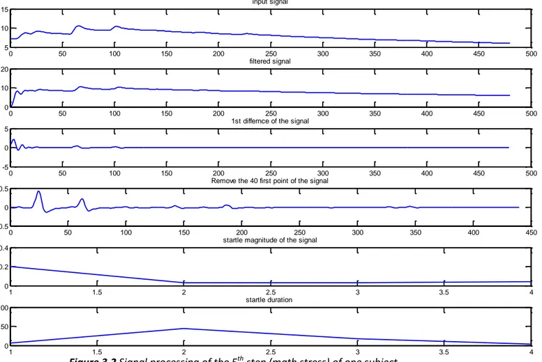
The use of the “ellip” function from Matlab creates the digital filter and the “filter” function applies it. Also notice that in the original signal “Figure3.1” there is a big difference in the SCL (skin conductance level) depending on the subject under measurement. The use of the first difference brings the signal down to the zero level while keeping the original variation. The “diff” function does the job by calculating the difference between adjacent values. Also notice at “Figure 3.1” that the signal is divided into 6 segments (0, 720, 1200, 21600, 2650, 3140 and 3600). Each segment represents a different measurement step in which the subject is measured under different conditions. These are “baseline, deep breath, relax, non verbal stress, math stress, relax”. Note that at the beginning of each step, the signal presents a significant change in level. This happens because between steps there is 15 minute break and the SC sensor needs to be adjusted to the subject’s finger. The remove of 35~40 points at the beginning of every step is essential to get rid of this settling start time.
The above functions i.e. filter-first difference and startle removal are shown graphically in “Figure3.2” and also the startle magnitude-duration which are explained in the next paragraph. The subject signal used is taken accidentally but the step used is the 5th step (math stress) which is of great importance as the subject is under high stress conditions. The Matlab code used is shown in Appendix A.
[13] SCR Amplitude and Duration
The remaining part of the signal processing is the feature extraction from the filtered, differentiated and ringing free signal, to indicate the stress level of the subject under test. As stated in [9] the best features for that purpose are the SCR amplitude, latency, rising time and recovery time of the response as well as the SCL.
The idea to locate those features is to try to locate the points where there is a significant startle of the signal which is the actual response. The significance is a value that can be adjusted and is highly depended on the SC sensor. The SCL is not under consideration anymore as signal’s level is down to zero through the “diff” function and as mentioned in theory the SCL differs from person to person. After location pointing of the startles we need to find the amplitude and the duration up to that point. This is done by finding the maximum point between the current and the next startle. The difference between the start and the end in amplitude and time gives the actual magnitude and duration of the current startle. “Figure3.3” shows graphically the results of the above idea. 1st graph is the original signal, 2nd filtered, 3rd first difference, 4th 40startles removal, 5th startle magnitude and 6th startle duration. Appendix B shows more graphically results to understand the logic of the algorithm and at the latest part of Appendix A is the Matlab code.
Figure 3.3
Signal processing of the 3rd step (non-verbal stress stage) of a subject. Magnitude, 5th graph, is an integer value. In this example 11 startles found with amplitude up to 0,4. Duration, 6th
graph, is the duration in time of each startle.
0 100 200 300 400 500 600 700 800 900 1000 8 10 12 14 0 100 200 300 400 500 600 700 800 900 1000 0 5 10 15 0 100 200 300 400 500 600 700 800 900 1000 -2 0 2 4 0 100 200 300 400 500 600 700 800 900 1000 -0.5 0 0.5 1 2 3 4 5 6 7 8 9 10 11 0 0.2 0.4 1 2 3 4 5 6 7 8 9 10 11 0 50 100 150
[14] SCR Features Used
The amount of features must be constant to be used effectively in NN and CBR. As shown in the previous sections the amount of startles and their duration vary depending on the waveform. Some methods exist that deal with the problem of fulfilling the number of features like interpolation, zero assignment and statistical methods. As a first approach the last method was used because of its easiness. The following 11 features produced:
“Numberofstartles, MeanAmplitude, MeanTime, StandardDeviationAmplitude, StandardDeviationTime, Minamplitude, MinTime, Maxamplitude, MaxTime, Medianamplitude, MedianTime”.
Further work need to be done with the other two techniques (interpolation and zero assignment) to compare results.
[15] 3.3 FT using Neural Network
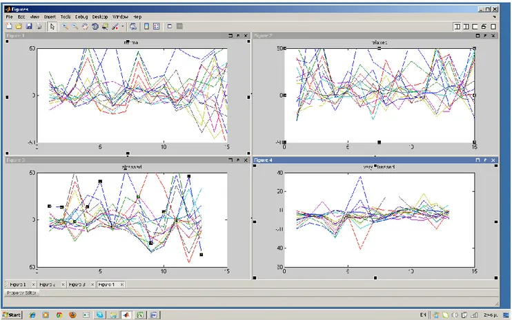
At the figure follows are the FT 15 samples (slopes) from 63 subjects (humans) in time base. The 15 features represent the angle of change for a 15 min measurement of all the measurement stages i.e. “baseline, deep breath, relax, non verbal stress, relax, math stress, relax” of each subject. This technique is used in [3] and it is a standardized method. The four graphs in “Figure 3.4” are the subjects’ signals grouped as normal, very relaxed, relaxed, stressed and very stressed, as characterized by the clinician expert.
By visual inspection of the graphs one can see that the expert’s classification into “normal, very relaxed, relaxed, stressed and very stressed” does not show any similarity among each subject. i.e. looks difficult for a pattern to exist that categorize a person’s stress state. In the remaining of this chapter the results of the NN techniques show, unexpectedly, promising results.
Figure 3.4 Four different stress states as characterized by the clinician expert from 63 subjects
[16] FT slope features with Pattern recognition tool. Experiment 1
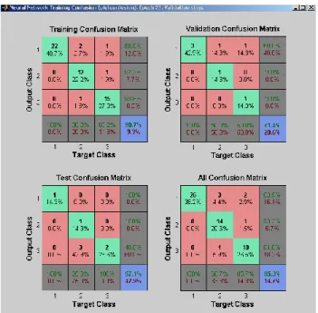
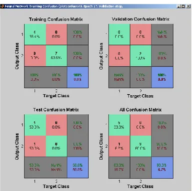
Figure 3.5 shows the pattern recognition algorithm output from Matlab. The output is a confusion matrix which is a specific table layout that allows visualization of the performance of the algorithm. In this network the 63 subjects where tried to be classified into 3 main categories “normal, stressed and relaxed”. The other 2 “very relaxed and very stressed” where embodied into the “relaxed and stressed” categories for simplicity. The output of 85% success was the best accomplished among different training methods. The method uses 25 neurons and Appendix C shows the Matlab code.
Figure 3.5 Confusion results of 3 classes
Experiment 2
The next experiment was an effort to classify the dataset not by the “expert classification” but by the step of the measurement. We choose 2 classes regarding the step of measurement. That is for the steps “deep breath - relax1 - relax2” we consider it relax and for “non verbal stress-math stress” we consider it as stress.The results are shown in figure 3.6. The Matlab code was the same as the previous experiment and we gain 93% success classification!
[17]
Figure 3.6 Confusion results of 2 classes Experiment 3
In this experiment the effort was to classify the data into 5 classes as normal for step “baseline”, very relaxed for “deep breath”, relax for steps “relax1 - relax2”, stress for “non verbal stress” and very stressed for “math stress”. The results are shown to the following figure. The Matlab code was also the same as the previous experiments. The results weren’t as successful as before with only 20% success classification.
[18]
The results from the experiments above shown that the angle of change features can classify the subject using both the expert’s classification and the step of measurement. Nevertheless, in the sense of reality if someone is under stress conditions i.e. driving a truck in a mine or the time before a student present his thesis project, the good result relies on whether the subject can cope up well under these circumstances. Under this fact the expert’s classification is the only doubtless criterion.
Comparing the above experiments we realize that the extra classification of “normal” significantly reduces the output success rate. So we came to the result that for FT with features derived from the angle of change and by using pattern recognition NN we can use only two classes for stress detection. “Stressed and no-stressed”.
FT slope features using NN Fitting Tool
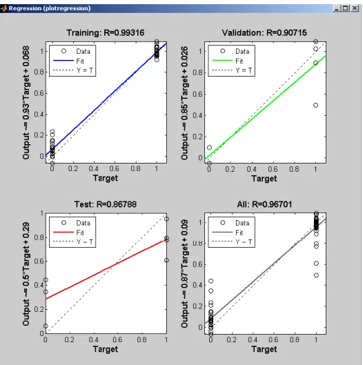
In this experiment the fitting tool of Matlab was used to fit the 63 FT samples as before into the two expert classes (stressed – not stressed). The regression output is a statistical measure that shows the strength of the relationship between input and output. The total regression of 0.967 is very promising. Appendix D shows the corresponding Matlab code.
[19]
4. Results
In section 3.1 “problem formulation and analysis” a summary of the practical works was described. In this chapter the results of the corresponding experiments will be shown with the use of tables. In summary, the three features will be compared against the expert classification and with the two different AI methods (NN and CBR).
The two CBR platforms used were Fuzzy CBR which is developed by MDH University and myCBR an open-source case-based reasoning tool developed at DFKI. In the current experiment myCBR were configured for Euclidean similarity function and same weights for each feature, while Fuzzy CBR configured with fuzzy similarity and also same weights. The use of two CBR platforms were used for verification and also because the myCBR gives you the freedom of arbitrary number of features which is the case in the SCR features.
The measurement data are from the 18 cases from Volvo. The SC slope and FT slope features are extracted from the Fuzzy CBR platform. The SCR are the features as calculated in the current thesis work. (Section 3.2)
4.1 The Features on CBR platforms against expert classification
In this section the results are shown from the output of the two CBR platforms and are compared to expert’s diagnosis. The comparison is limited to stressed and normal without the sub-categories very stressed and relaxed. Table 1.1 and 1.2 shows the comparison of SC and FT slope features on both CBR platforms while 1.3 shows SCR on MyCBR only because the Fuzzy CBR platform is dedicated to slope features. The result is a useful metric of the efficiency of the methods under test.
For each case a classification from the expert is shown (col 1) and is compared to the expert’s classification of the similar case (col 3, 5, 7, 9) that the CBR platform produces. “1” is inserted when the cases have similar expert classification and “0” when different. The Expert similarity row shows the percentage similarity of all the cases from the 1st and the 2nd similar case output of the CBR platforms. The Expert similarity total row is the total percentage with 0,6 weight for the 1st similar case and with 0,4 weight of the 2nd similar case. The 0,6 and 0,4 weights were arbitrary chosen for the creation of a single overall score.
What is shown is that the SC slope gives quite promising results with 83% similarity to the expert classification on both Fuzzy and MyCBR platforms. The FT slope also gives good results (83%) but only on the MyCBR platform and it’s a result that may need to be further researched (green boxes). Finally the SCR don’t give good results which mean that SCR feature extraction algorithm need re-examination with the interpolation and zero assignment techniques.
[20]
Feature SC slope
CBR platform fuzzy cbr mycbr
Expert classification Volvo caseNo 1st similar case ”1” correct, ”0” false classification 2nd similar case ”1” correct, ”0” false classification 1st similar case ”1” correct, ”0” false classification 2nd similar case ”1” correct, ”0” false classification Stressed 1 5 1 6 0 5 1 11 1 Normal 2 13 1 16 0 13 1 15 1 Stressed 3 5 1 10 1 18 1 10 1 Normal 4 13 1 3 0 18 0 13 1 Stressed 5 1 1 3 1 1 1 11 1 Normal 6 1 0 7 0 1 0 7 0 Stressed 7 11 1 1 1 11 1 1 1 Stressed 8 7 1 11 1 11 1 2 0 Normal 9 10 0 6 1 10 0 18 0 Stressed 10 3 1 9 0 12 1 3 1 Stressed 11 8 1 7 1 5 1 7 1 Stressed 12 10 1 4 0 10 1 18 1 Normal 13 7 1 15 1 15 1 4 1 Stressed 14 16 1 2 0 3 1 18 1 Normal 15 13 1 16 0 10 0 17 1 Stressed 16 7 1 11 1 5 1 1 1 Normal 17 16 0 11 0 16 0 13 1 Stressed 18 7 1 3 1 3 1 10 1 Expert similarity (%) 0,83 0,50 0,72 0,83
Expert similarity total
(%) 0,70 0,77
[21]
Feature FT slope
CBR platform fuzzy cbr Mycbr
Expert classification Volvo caseNo 1st similar case ”1” correct, ”0” false classification 2nd similar case ”1” correct, ”0” false Classification 1st similar case ”1” correct, ”0” false classification 2nd similar case ”1” correct, ”0” false classification Stressed 1 8 1 7 1 8 1 18 0 Normal 2 3 0 6 1 6 1 4 1 Stressed 3 2 0 6 0 15 0 14 1 Normal 4 2 1 3 0 15 1 10 0 Stressed 5 9 0 13 0 9 0 13 0 Normal 6 17 1 15 1 17 1 16 0 Stressed 7 3 1 2 0 15 0 4 0 Stressed 8 12 1 1 1 1 1 18 1 Normal 9 5 0 13 1 13 1 15 1 Stressed 10 18 1 14 1 18 1 15 0 Stressed 11 12 1 13 0 12 1 8 1 Stressed 12 13 0 11 1 11 1 18 1 Normal 13 12 0 9 1 9 1 12 0 Stressed 14 16 1 10 1 16 1 15 0 Normal 15 3 0 14 0 4 1 10 0 Stressed 16 14 1 17 0 14 1 15 0 Normal 17 6 1 1 0 6 1 16 0 Stressed 18 10 1 12 1 10 1 8 1 Expert similarity (%) 0,61 0,56 0,83 0,39
Expert similarity total
(%) 0,59 0,66
[22]
CBR platform Mycbr
Features SCR
Expert classification Volvo caseNo
1st similar case
”1” correct, ”0” false
classification 2nd similar case
”1” correct, ”0” false classification stressed 1 9 0 6 1 normal 2 15 0 13 0 stressed 3 4 0 6 0 normal 4 3 0 14 0 stressed 5 1 1 18 1 normal 6 3 0 1 0 stressed 7 16 1 1 1 stressed 8 11 1 1 1 normal 9 4 1 1 0 stressed 10 4 0 14 1 stressed 11 8 1 16 1 stressed 12 3 1 15 0 normal 13 15 1 2 1 stressed 14 4 0 3 1 normal 15 2 1 13 1 stressed 16 7 1 15 0 normal 17 16 0 13 1 stressed 18 5 1 1 1 Expert similarity (%) 0,56 0,61
Expert similarity total (%) 0,58
[23]
4.2 Neural Network Pattern Recognition and Features comparison
Here the pattern recognition tool of Matlab was used to classify the three different features for stress detection of the 18 Volvo cases. In pattern recognition a confusion function calculates the true/false results from comparing network output classification with target classes i.e. clinician expert.
The Matlab code and the network used are shown in Appendix E and the confusion results are in the following figures 4.1, 4.2 and 4.3. The results are as follows: FT slope 61.1%, SC slope 38.9% and SCR 38.9%.
The results are not so promising. In the experiment section both pattern recognition and fitting tool produce good results. The main reason is that only 18 cases were used whereas in the experiment part the cases were 63. Also, the NN acts as a black-box producing different result in each iteration. This doesn’t give any confidence to the engineer.
[24]
Figure 4.1sc_slope confusion
[25]
5. Conclusion – Future Work
Stress detection is an area where biomedical and engineer scientists experiment the last decades. Mälardalen University’s IDT Artificial Intelligence Research Group has done enormous work in that area and shown great results. The current thesis intention was to discover the area and to extract useful results for the current and the following researchers. It is proved that the SC slope features provide similar results to that of the FT slope, and the Fuzzy CBR platform were validated by the comparison to the ‘MyCBR’ one. Less successful was the SCR feature extraction, but the techniques used were effective especially until the point of detection of the No of startles, their amplitude and duration as the algorithm follows the approved method of the biologists. Finally, regarding the NN part it cannot be said that one can count on its reliability mostly because the only control was the visual inspection of the signals and in that aspect they weren’t promising much.
Acknowledgement
The positive part during my work was the guidance from the supervisors or else I could have easily been lost to the interspersed information. Finally I end up to useful results that could help the followers.
To wind up, I want to thank my supervisors for their help and the knowledge that I gain from them and to wish them good luck for that enormous project that they are engaged with.
Theodore Belogiannis,
[26]
Appendices
AppendixA
SCR feature extraction Matlab code
clc
clearall
closeall
openfileforimportintovariablecalledsignal
uiimport;
Fs=31; %sampling freq for the gigital filter
lgsr=length(signal); %length of the array
%the design-creation of an elliptic LPF filter @4Hz follows
%b-a coefficients, n= 4th order, Rp=0.1 dB of rpple in the passband %Rs=40 dB stopband down from the peak value,
%Wp normalized pass band edge frequency [b,a]=ellip(4,0.1,40,4*2/Fs);
%the frequency response of the digital filter (FFT) %H freq response vector, W angular response vector [H,W]=freqz(b,a,lgsr);
%the digital filter of signal with coefficients b and a signalfiltered=filter(b,a,signal);
%take the 1st difference of the signal
%add here the abs value may produce good results signalfiltereddiff=diff(signalfiltered);
%signalfiltereddiffabs=abs(signalfiltereddiff); %exclude the first 35~40 points because of ringing s=signalfiltereddiff(35:lgsr-1);
l=length(s);
noise_limit=0.0001; %some threshold to remove noise, experiment 0.0099
vector=s;
overthresh=find(vector>noise_limit); %is the signal timestamp of that
threshold
overthresh35=overthresh+35; %raise up timestamp by 35 as removed before for
ringing exclusion
startles=diff(overthresh); %show the startles
startles35=diff(overthresh35); %may not be neccessary
signif_startles=find(startles>10); %is the index of gaps bigger than this
value e.g 31 by experiment
start=[]; %is the s timestamp for the significant startles that exceed the
noise noise_limitold and the startle magnitude threshold
for i=1:length(signif_startles)%value of s at big_gap timestamp
start=[start overthresh35(signif_startles(i)+1)];
end;
finish = [];
for i=1:(length(start)-2)%-1 for apropriatecomparisor in the max function
later between the startles
startit=start(i); %one startle
endit=start(i+1);%next startle
[val, loc]=max(s(startit:endit)); %max returns the value and the
position of the maximum point found
finish(i)=startit+loc;%the end of the startle is at the start + the next
highest peak
end;
[27] time=[]; for i=1:length(finish) time(i)=finish(i)-start(i); amplitude(i)=s(finish(i))-s(start(i)); end; createfigures_3_auto(amplitude, s, time);
createfigures3auto(signal, signalfiltered, signalfiltereddiff, s, amplitude, time); outNo=i; outMeanAmplitude=mean(amplitude); outMeanTime=mean(time); outstdAmplitude=std(amplitude); outstdTime=std(time); outminamplitude=min(amplitude); outminTime=min(time); outmaxamplitude=max(amplitude); outmaxTime=max(time); outmedianamplitude=median(amplitude); outmedianTime=median(time); Features=[outNo,outMeanAmplitude,outMeanTime,outstdAmplitude,outstdTime,outm inamplitude,outminTime,outmaxamplitude,outmaxTime,outmedianamplitude,outmedi anTime];
[28]
Appendix B
SCR features results
Followed are graphs from SCR extraction as shown in Matlab. Each one represents a
person’s 6 steps measurements. The reason for this representation is for visual inspection of the output from different subjects (4 subjects graphs are shown). For that reason all plots have the same scale for better discrimination.
0 5 10 15 20 25 0 0.05 0.1 A m p lit u d e
Magnitude of significant startles
0 500 1000 1500 2000 2500 3000 3500 -0.2 0 0.2 A m p lit u d e
Original signal Filtered @4Hz, Differentiated and exclude the 40 start points
0 5 10 15 20 25 0 200 400 N o o f p o in ts Duration of Startles
[29] 0 5 10 15 20 25 0 0.05 0.1 A m p lit u d e
Magnitude of significant startles
0 500 1000 1500 2000 2500 3000 3500 -0.2 0 0.2 A m p lit u d e
Original signal Filtered @4Hz, Differentiated and exclude the 40 start points
0 5 10 15 20 25 0 200 400 N o o f p o in ts Duration of Startles 0 5 10 15 20 25 0 0.05 0.1 A m p lit u d e
Magnitude of significant startles
0 500 1000 1500 2000 2500 3000 3500 -0.2 0 0.2 A m p lit u d e
Original signal Filtered @4Hz, Differentiated and exclude the 40 start points
0 5 10 15 20 25 0 200 400 N o o f p o in ts Duration of Startles
[30] 0 5 10 15 20 25 0 0.05 0.1 A m p lit u d e
Magnitude of significant startles
0 500 1000 1500 2000 2500 3000 3500 -0.2 0 0.2 A m p lit u d e
Original signal Filtered @4Hz, Differentiated and exclude the 40 start points
0 5 10 15 20 25 0 200 400 N o o f p o in ts Duration of Startles
[31]
Appendix C
Pattern Recognition with FT feature Matlab code
inputs = ft_in; targets = ft_out;
% Create a Pattern Recognition Network hiddenLayerSize = 25;
net = patternnet(hiddenLayerSize);
% Choose Input and Output Pre/Post-Processing Functions
net.inputs{1}.processFcns = {'removeconstantrows','mapminmax'};
net.outputs{2}.processFcns = {'removeconstantrows','mapminmax'};
% Setup Division of Data for Training, Validation, Testing
net.divideFcn = 'dividerand'; % Divide data randomly
net.divideMode = 'sample'; % Divide up every sample
net.divideParam.trainRatio = 80/100; net.divideParam.valRatio = 10/100; net.divideParam.testRatio = 10/100;
net.trainFcn = 'trainbfg'; %Levenberg-Marquardt
% Choose a Performance Function
net.performFcn = 'msereg'; % Mean squared error
net.performParam.ratio = 0.5; net.trainParam.show = 5; net.trainParam.epochs = 50; net.trainParam.goal = 0; % Choose Plot Functions
net.plotFcns = {'plotperform','plottrainstate','ploterrhist', ...
'plotregression', 'plotconfusion', 'plotroc'}; % Train the Network
[net,tr] = train(net,inputs,targets); % Test the Network
outputs = net(inputs);
errors = gsubtract(targets,outputs); performance = perform(net,targets,outputs)
% Recalculate Training, Validation and Test Performance trainTargets = targets .* tr.trainMask{1};
valTargets = targets .* tr.valMask{1}; testTargets = targets .* tr.testMask{1};
trainPerformance = perform(net,trainTargets,outputs) valPerformance = perform(net,valTargets,outputs) testPerformance = perform(net,testTargets,outputs) figure, plotconfusion(targets,outputs)
[32]
Appendix D
Fitting tool with FT feature Matlab code
inputs = ft_in'; targets = ft_out';
% Create a Fitting Network hiddenLayerSize = 15;
net = cascadeforwardnet(hiddenLayerSize);
% Choose Input and Output Pre/Post-Processing Functions
net.inputs{1}.processFcns = {'removeconstantrows','mapminmax'};
net.outputs{2}.processFcns = {'removeconstantrows','mapminmax'};
% Setup Division of Data for Training, Validation, Testing
net.divideFcn = 'dividerand'; % Divide data randomly
net.divideMode = 'sample'; % Divide up every sample
net.divideParam.trainRatio = 80/100; net.divideParam.valRatio = 10/100; net.divideParam.testRatio = 10/100;
net.trainFcn = 'trainbfg'; %Levenberg-Marquardt
net.performFcn = 'msereg'; % Mean squared error
net.performParam.ratio = 0.5; net.trainParam.show = 5; net.trainParam.epochs = 50; net.trainParam.goal = 0;
net.plotFcns = {'plotperform','plottrainstate','ploterrhist', ...
'plotregression', 'plotconfusion', 'plotroc'}; % Train the Network
[net,tr] = train(net,inputs,targets); % Test the Network
outputs = net(inputs);
errors = gsubtract(targets,outputs); performance = perform(net,targets,outputs)
% Recalculate Training, Validation and Test Performance trainTargets = targets .* tr.trainMask{1};
valTargets = targets .* tr.valMask{1}; testTargets = targets .* tr.testMask{1};
trainPerformance = perform(net,trainTargets,outputs) valPerformance = perform(net,valTargets,outputs) testPerformance = perform(net,testTargets,outputs)
[33]
Appendix E
Pattern Recognition Matlab code
input = sc_features'; %# each column is an input vector
ouputActual = expert';
net = newpr(input, ouputActual, 2); %# 1 hidden layer with 2 neurons
net.divideFcn = ''; %# use the entire input for
training
net = init(net); %# initialize net
net = train(net, input, ouputActual); %# train
[34]
References
[1] Ahmed, M.U., Begum, S., Funk, P., Xiong, N., Schéele, B.V, (2011), A Multi-Module Case Based Biofeedback System for Stress Treatment, Artificial Intelligence in Medicine, 51(2), 107-115.
[2] Begum, S., Ahmed, M.U., Funk, P., Xiong, N., and Schéele, B.V, (2009), Case-Based Decision Support System for Individual Stress Diagnosis Using Fuzzy Similarity Matching, The Journal of Computational Intelligence (CI), vol 25, nr 3, p180-195(16),Blackwell Publishing. [3] Begum, S., Ahmed, M.U., Funk, P., Xiong, N., Folke, M, (2011), Case-Based Reasoning Systems in the Health Sciences: A Survey on Recent Trends and Developments, IEEE
Transactions on Systems, Man, and Cybernetics, Part C: Applications an Reviews, 41(4), 421-434.
[4] Bakker Jorn, Mykola Pechenizkiy, Natalia Sidorova,(2011), ICDM Workshop , What’s your current stress level? Detection of stress patterns from GSR sensor data.
[5] Cheng M.-Y, H.-C. Tsai, Y.-H. Chiu, Journal (2009), Fuzzy case-based reasoning for coping with construction disputes, Expert Systems with Applications.
[6] Farooq Azam, Journal (2000), Biologically Inspired Modular Neural Networks, Blacksburg Virginia.
[7] Haley A. Jennifer, Journal (2000), Wearable and Automotive Systems for Affect Recognition from Physiology.
[8] Rigas George, Yorgos Goletsis, and Dimitrios I. Fotiadis, Journal (2012), Real-Time Driver’s Stress Event Detection.
[9] Stefan Schmidt and Harald Walach, (2000), Electro Dermal Activity (EDA) Research – State of the art measurement and techniques for Parapsychological purposes.
[10] GmbH (DFKI), Deutsche Forschungszentrum für Künstliche Intelligenz, The German Research Center for Artificial Intelligence, url: http://www.dfki.de/web/competence/cccbr
[35]
Comments
The important part of comments was limited by the examiner as no opponents appeared! Nevertheless his opinion is of great importance as the subject of the thesis is his main area of study. Apart of the importance of references everything inside the report; he also mentioned the importance of the very detailed analysis of the results, even for the presentation, because in medical science the procedure of measurements and the simplifications must be clearly shown for further investigations.
![Figure 2.2 Palmar Electrode Sides[9]](https://thumb-eu.123doks.com/thumbv2/5dokorg/4554402.116089/8.892.273.623.542.876/figure-palmar-electrode-sides.webp)
