http://www.diva-portal.org
Postprint
This is the accepted version of a paper published in Scripta Materialia. This paper has been peer-reviewed but does not include the final publisher proof-corrections or journal pagination.
Citation for the original published paper (version of record):
Hernando, J C., Elfsberg, J., Ghassemali, E., Dahle, A., Diószegi, A. (2019) The effect of coarsening of primary austenite on the ultimate tensile strength of hypoeutectic compacted graphite Fe-C-Si alloys
Scripta Materialia, 168: 33-37
https://doi.org/10.1016/j.scriptamat.2019.04.010
Access to the published version may require subscription. N.B. When citing this work, cite the original published paper.
Permanent link to this version:
The effect of coarsening of primary austenite on the ultimate tensile
strength of hypoeutectic compacted graphite Fe-C-Si alloys
Juan Carlos Hernando
1,a,*, Jessica Elfsberg
2,b, Ehsan Ghassemali
1,c, Arne K.
Dahle
1,d, Attila Diószegi
1,e1Jönköping University, School of Engineering, Department of Materials and Manufacturing, P.O. Box
1026, SE-551 11, Jönköping, Sweden
2Scania CV AB, SE-151 87 Södertälje, Sweden
aJuan-Carlos.Hernando@ju.se, bJessica.Elfsberg@scania.com, cEhsan.Ghassemali@ju.se, dArne.Dahle@ju.se, eAttila.Dioszegi@ju.se,
*Corresponding author
Abstract
The effect of primary austenite morphology on the ultimate tensile strength (UTS) of hypoeutectic compacted graphite Fe-C-Si alloys (CGI) is studied by isothermal coarsening experiments. Secondary dendrite arm spacing (SDAS) and the morphological characteristics related to the surface area of primary austenite, Mγand DID
Hyd
, increase with the cube root of coarsening time. UTS decreases linearly with increasing coarseness of primary austenite. The eutectic and eutectoid microstructures are unaffected by the primary austenite morphology. These observations demonstrate the strong influence of primary austenite morphology on the mechanical properties of hypoeutectic CGI alloys.
Keywords: Coarsening, Dendrites, Mechanical Properties, UTS, Compacted Graphite Iron
Extensive research is being carried out worldwide to improve the properties of cast alloys by extending the understanding and prediction of solidification. Microstructure formation in hypoeutectic alloys starts with the nucleation and growth of dendritic microstructures during primary solidification and coarsening of the dendrites occurs throughout solidification. During coarsening, dendrites are subjected to diffusional mass transfer [1] controlled by the local interfacial curvature [2], where the solid-liquid system minimizes its free energy resulting in a reduction of the solid-liquid interfacial area over time [3]. This promotes significant morphological changes of the dendritic microstructure, including remelting of small branches [4, 5], multiplication [6] and coalescence [7, 8]. Coarsening is particularly important after dendrite coherency, when free growth stops and the feeding shifts from mass to interdendritic [9]. Subsequently, the eutectic reaction occurs in the interdendritic regions [10] and solidification is completed.
In hypoeutectic Fe-C-Si alloys, primary austenite nucleates and forms dendritic crystals which coarsen during solidification [11, 12]. During the eutectic reaction, graphite and eutectic austenite nucleate and grow in the interdendritic regions until the end of solidification [13]. In the cases of lamellar (LGI) and compacted graphite iron (CGI), these two phases grow cooperatively, while in spheroidal graphite iron (SGI) they grow as a divorced eutectic [13]. During a later eutectoid reaction, austenite transforms into pearlite, ferrite or a mixture of these phases [14].
Several models have been proposed for predicting the mechanical properties of LGI. Statistical models were initially developed based on regression analysis of microstructural features [15] or the composition of the alloy [16]. Later, physical models based on the Griffith fracture model for brittle materials [17] used the maximum length of graphite to predict the ultimate tensile strength (UTS) [16, 18]. This model was further modified considering the diameter of eutectic cells and the so-called “diameter of primary austenite” [19]. Despite the agreement on the detrimental effect of increasing graphite length on UTS, there are contradictory results regarding the influence of eutectic cell size. Several studies have shown that increasing eutectic cell size causes a decrease in UTS [20-22]. However, there have been observations of the opposite effect, where the smallest eutectic cell size yields the lowest UTS [10].
The pearlite lamellar spacing (PLS) was introduced in combination with the graphite length [23] to incorporate the effect of the eutectoid microstructure into the model. In the last decade, a new approach based on the Griffith model, predicts the UTS of pearlitic LGI based only on the morphology of primary austenite [24]. The model was developed based on results from experiments conducted with conditions yielding simultaneous variations in primary, eutectic and eutectoid microstructures. The UTS was modeled based on the size and morphology of the interdendritic regions assuming that they control the mechanical properties regardless of the size and distribution of the eutectic cells [24].
CGI has become a popular material due to its excellent combination of mechanical and thermal properties [25]. However, the limited understanding of the correlation between microstructure and the mechanical properties limits the optimization of CGI.
This study investigates the effect of primary austenite on the eutectic and eutectoid microstructure and UTS of CGI. The main aim of this work is to correlate microstructure and UTS for CGI and to investigate the validity of the model for UTS developed by Fourlakidis and Diószegi [24]. Experiments involving isothermal holding in the semi-solid state are used to promote the coarsening of the primary microstructure, leaving the cooling conditions during eutectic and eutectoid reactions unaffected. The alloy used in this work was a hypoeutectic Fe-C-Si alloy with the composition of 3.4%C, 2.5%Si, 0.03%P, 0.01%S, 0.063%Mg, 0.7% Mn, 0.9% Cu (wt.%) measured by optical emission spectrometry (OES) [26]. 50 mm diameter and 300 mm height rods were cast in sand molds and subsequently machined to a diameter of 38 mm and height of 42 mm. The rods were melted and held at 1450°C inside a 40 mm diameter alumina crucible under Ar atmosphere to reach a chemistry corresponding to CGI by partially reacting the Mg in the alloy [27]. The samples were cooled inside the furnace to 1163°C which is above the eutectic temperature for this alloy. Next, the samples were held isothermally for different times (0, 10, 30 and 60 min) to promote coarsening of the dendrites. The experiment is described in more detail elsewhere [27, 28]. Subsequently, the samples were cooled to room temperature inside the furnace, thus providing similar conditions for eutectic solidification and eutectoid transformation.
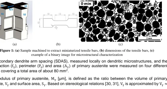
Miniaturized tensile bars were machined and polished from the samples at a half-radius distance from the center of the cylinder, as shown in Fig. 1(a). Dimensions of the tensile bars are shown in Fig. 1(b) and the thickness was 1.8±0.2 mm in order to contain several eutectic cells. Miniaturized tensile tests (MTT) were performed at room temperature in a loading stage with a crosshead displacement rate of 10 µm/s with 4 bars for each condition. After the MMT, the samples were etched in a picric-based solution to reveal the microstructure [29]. Microstructural analysis was performed by optical and scanning electron microscopy (SEM). Micrographs of the etched samples were transformed into binary images where primary austenite and eutectic cells were represented as entities in black, as shown in Fig 1(c). Image analysis was performed with Olympus Stream Motion Desktop 1.9.1 software.
(a) (b) (c)
Figure 1: (a) Sample machined to extract miniaturized tensile bars, (b) dimensions of the tensile bars, (c) example of a binary image for microstructural characterization
The secondary dendrite arm spacing (SDAS), measured locally on dendritic microstructures, and the area fraction (fγ), perimeter (Pγ) and area (Aγ) of primary austenite were measured on four different regions covering a total area of about 80 mm2.
The modulus of primary austenite, Mγ [μm], is defined as the ratio between the volume of primary austenite, Vγ and surface area, Sγ. Based on stereological relations [30, 31], Vγ is approximated by Vγ≈
Aγ and Sγ by Sγ≈ 4
πPγ. Thus, Mγ [μm] was calculated as Mγ≈ π 4
Aγ
Pγ. Similarly, the hydraulic diameter of the interdendritic region, DIDHyd [μm], was calculated as the ratio between the volume of the interdendritic region, VID, and the surface area, SID. Considering that SID≈ Sγ, the same stereological relations and the relationship between primary austenite area (Aγ) and the total area of the micrograph (AT), the area of the interdendritic region (AID) is calculated as AID≈ AT− Aγ and thus, DID
Hyd ≈π 4 AID PID ≈ π 4 (AT−Aγ) Pγ . The
shortest distance between the center of gravity of primary austenite crystals and their surrounding crystals, DγNN [μm], was measured on all the austenite crystals in the micrograph.
The eutectic microstructure was characterized by the area fraction (fEC), number (EC/mm2), size (DiamEC)
and spatial distribution (DECNN) of eutectic cells. Additionally, before the MTT, the nodularity, area fraction
and the mean and maximum length of graphite were determined according to ISO 16112:2006(E) [32] on multiple regions covering a total area of about 24 mm2. The maximum length of graphite was
calculated considering the largest 1% of the graphite particles.
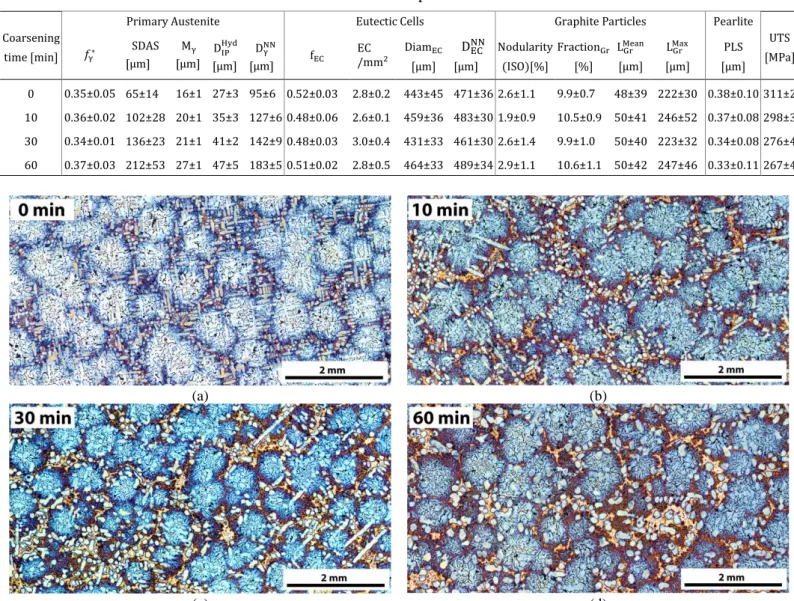
The pearlite lamellar spacing (PLS) was determined on SEM images. The SEM was operated at a constant magnification and an acceleration voltage of 15kV. Ten images were taken for each sample and the PLS was determined in the regions with the most refined pearlite containing at least 10 lamellae. The microstructures after isothermal coarsening experiments are shown in Fig. 2. Morphological changes occurring in the dendritic microstructure during coarsening are visible in the micrographs. The microstructure is initially very dendritic, highly branched and interconnected, with secondary arms visible, Fig. 2(a). As the coarsening time increases, the surface area of the dendrites is reduced, increasing the length scale and showing an overall more globular microstructure, Fig. 2(c-d).
The morphological characteristics of the primary austenite were determined from the micrographs shown in Fig. 2 and are presented in Table 1. The fraction of austenite, 𝑓γ∗ , was determined from fγ assuming a uniform distribution of primary austenite even in regions covered by eutectic cells.
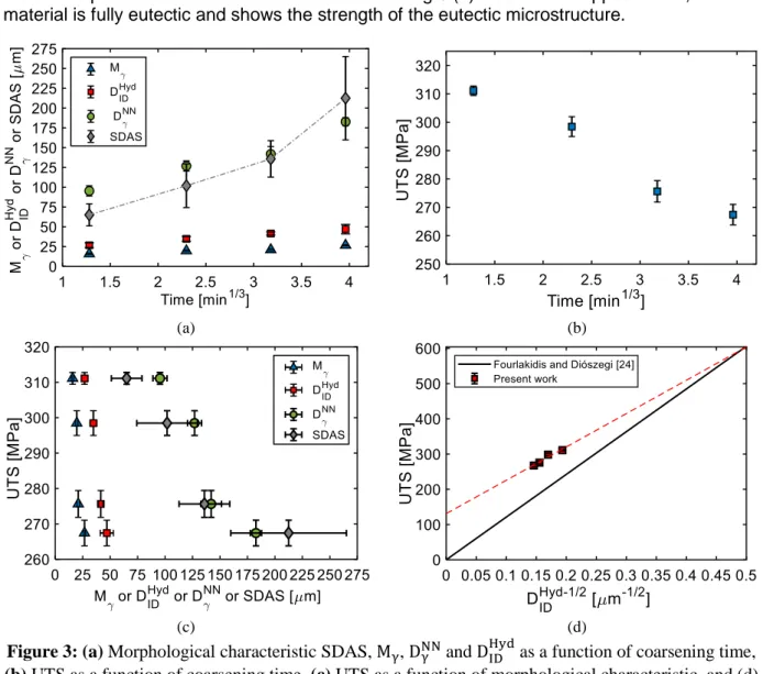
SDAS is shown as a function of the cube root of coarsening time, 𝑡1/3, in Fig. 3(a). SDAS shows a
perfectly linear relation with increasing coarsening time up to 30 min in good agreement with the literature [33, 34]. However, the result for the 60 min sample does not fit the relation and shows a large error. This could be because SDAS is measured on a random 2-D section of the microstructure and detached arms may move in the liquid.
The increase in modulus, Mγ, in Table 1 is a result of the reduction of surface area to volume of primary
austenite during coarsening. Mγis shown in Fig.3(a) as a function of the cube root of coarsening time,
𝑡1/3. There is a linear relationship in agreement with results from quenching experiments reported
previously [35] and observations for other alloys [2-4, 8].
Similarly, the hydraulic diameter of the interdendritic region, DIDHyd, increases with coarsening time, Table 1. This is a result of the reduction of the interdendritic surface area. DIDHyd also follows a linear relationship with the cube root of coarsening time, 𝑡1/3, as shown in Fig. 3 (a).
The distance between primary austenite crystals, DγNN, also increases with coarsening time as seen in
Table 1. DγNNis shown in Fig. 3(a) as a function of the cube root of coarsening time, 𝑡1/3; again, with a
linear relationship.
All parameters shown in Fig. 3(a) show a linear relationship with the cube root of coarsening time, 𝑡1/3,
except for SDAS for the longest coarsening time. This is the typical Ostwald ripening relation in agreement with previous studies [2, 5, 34, 36-38]. Therefore, shape-independent parameters describe more accurately the morphological characteristics of primary austenite during coarsening.
The micrographs in Fig. 2 show eutectic cells comprised of compacted graphite particles and eutectic austenite. Eutectic austenite is etched in darker blue compared to primary austenite due to different Si contents [29]. Eutectic cells appear quite spherical and it is difficult to distinguish any significant differences as a function of coarsening time. Table 1 shows that the fraction (fEC), number (EC/mm2), size
time. Similarly, the nodularity, fraction, and the mean and maximum length of graphite do not change considerably with coarsening time. Thus, the characteristics of the eutectic microstructure are not significantly affected by the morphology of primary austenite. These are significant findings as they show that the isothermal treatment, and thus the morphology of primary austenite, does not influence the nucleation frequency and growth of eutectic cells. Similar eutectic microstructures for all coarsening times can be attributed to the similar cooling conditions during the eutectic reaction and the constant alloy composition. Thus, the surface area of primary austenite and the size of the interdendritic channels do not influence the size and distribution of eutectic cells. The surface area of primary austenite could have been expected to influence the distribution of nucleant particles because of particle pushing and thereby influencing the eutectic microstructure.
Furthermore, it is worth noting that the maximum length of graphite is 44-50% of the mean eutectic cell diameter, while a previous study of LGI predicts the maximum graphite length to be approximately 95% of the mean eutectic cell diameter for a similar casting [18].
Table 1. Microstructural characteristics of the samples. The error shows the standard deviation.
Coarsening time [min]
Primary Austenite Eutectic Cells Graphite Particles Pearlite UTS [MPa] 𝑓γ∗ SDAS [µm] Mγ [µm] DIPHyd [µm] DγNN [µm] fEC EC /mm2 DiamEC [µm] DECNN [µm] Nodularity (ISO)[%] FractionGr [%] LMeanGr [µm] LMaxGr [µm] PLS [µm] 0 0.35±0.05 65±14 16±1 27±3 95±6 0.52±0.03 2.8±0.2 443±45 471±36 2.6±1.1 9.9±0.7 48±39 222±30 0.38±0.10 311±2 10 0.36±0.02 102±28 20±1 35±3 127±6 0.48±0.06 2.6±0.1 459±36 483±30 1.9±0.9 10.5±0.9 50±41 246±52 0.37±0.08 298±3 30 0.34±0.01 136±23 21±1 41±2 142±9 0.48±0.03 3.0±0.4 431±33 461±30 2.6±1.4 9.9±1.0 50±40 223±32 0.34±0.08 276±4 60 0.37±0.03 212±53 27±1 47±5 183±5 0.51±0.02 2.8±0.5 464±33 489±34 2.9±1.1 10.6±1.1 50±42 247±46 0.33±0.11 267±4 (a) (b) (c) (d)
Figure 2: Micrographs of etched samples after (a) 0, (b) 10, (c) 30, and (d) 60 min of isothermal coarsening.
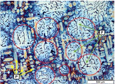
The pearlite lamellar spacing, PLS, reported in Table 1 is not significantly affected by coarsening time. Formation of ferrite in CGI is influenced by the morphology of compacted graphite, cooling conditions and chemical composition [25]. In this work, as shown in Fig. 4, it can be observed that ferrite is surrounding the compacted graphite particles, while the pearlite is observed in the interior of the coarsened primary austenite in the regions away from the graphite particles. As described earlier, the fraction of austenite and eutectic cells are not affected by coarsening time. Thus, we can expect a similar ratio of pearlite/ferrite in all micrographs. These results indicate that the eutectoid reaction is not influenced by the morphology of primary austenite.
Fig. 3 (b) shows UTS as a function of the cube root of coarsening time. A linear decrease in UTS with increasing coarsening time can be observed. Fig. 3(c) shows UTS as a function of the morphological characteristics of primary austenite (SDAS, Mγ, DID
Hyd
and
DγNN). Again, it can be observed that UTS
decreases. Given that SDAS is not an accurate characteristic of the primary austenite morphology for long coarsening times, as seen in Fig. 3(a), UTS does not correlate well, Fig. 3(c). This shows that Mγ and DIDHyd more accurately describe the effect of primary austenite on UTS.
These results demonstrate the critical role of primary austenite on the UTS of hypoeutectic Fe-C-Si alloys. For similar eutectic and eutectoid microstructures, primary austenite controls the mechanical properties regardless of graphite length, eutectic cell size and PLS thus contradicting previous models. These observations are in agreement with the model developed by Fourlakidis and Diószegi [24] for pearlitic LGI. Their model uses the hydraulic diameter of the interdendritic region, DIDHyd, in the Griffith fracture model, as it more accurately describes the length scale of the interdendritic region corresponding to the largest defect in the material. Fig. 3 (d) shows the model prediction of UTS as a function of DIDHyd.The model is based on experiments with simultaneous variations of the morphology of primary austenite, eutectic cell size, and PLS as a result of constant cooling conditions. However, in this study, the morphology of primary austenite has been varied independently of the eutectic and eutectoid microstructures. As can be observed in Fig.3 (d), the UTS is larger in the present work. This is expected because CGI is stronger than LGI due to the different graphite morphology. At DIDHyd= 0, the material is pure austenite and thus the two lines in Fig.3 (d) meet. At the opposite end, at the origo, the material is fully eutectic and shows the strength of the eutectic microstructure.
(a) (b)
(c) (d)
Figure 3: (a) Morphological characteristic SDAS, Mγ, DγNN and DID Hyd
as a function of coarsening time,
(b) UTS as a function of coarsening time, (c) UTS as a function of morphological characteristic, and (d)
UTS as a function of DIDHyd (−
1
Figure 4: Representative micrograph of the sample after 0 min of isothermal coarsening. The boundaries
of the fully observable eutectic cells are delimited. Examples of pearlite (P) and ferrite (F) regions are marked.
To summarize, the primary austenite in hypoeutectic compacted graphite Fe-C-Si alloy (CGI) has been coarsened isothermally for different times, while the cooling conditions for eutectic and eutectoid reactions have been kept constant. Primary austenite coarsens according to the Ostwald ripening model, while SDAS deviates for long coarsening times. The morphology of primary austenite during coarsening is more accurately described by the shape-independent parameters, Mγ, DID
Hyd
and DγNN. Primary austenite morphology does not significantly influence the eutectic and eutectoid microstructures, demonstrating that its surface area and the size of the interdendritic regions do not control the size and distribution of eutectic cells. The UTS decreases with increasing coarseness of primary austenite. This demonstrates the strong influence of primary austenite morphology on UTS of hypoeutectic CGI alloys when the eutectic and eutectoid microstructures are similar. These results are in good agreement with a recent model of the mechanical properties of LGI [24] where the hydraulic diameter of the interdendritic region, DIDHyd, is used in the Griffith fracture model. This work shows the isolated effect of primary austenite on UTS, emphasizing the importance of incorporating the morphology of the primary microstructure in the models. Future work should be directed towards understanding the contributions to strength from graphite morphology, eutectic cell size, pearlite/ferrite ratio and pearlite lamellar spacing. The validation of this model in SGI should also receive future efforts. Acknowledgments
This research was funded by VINNOVA, the Swedish Agency for Innovation, through the research projects CastDesign, grant number (2013-03303) and SPOFIC II, grant number (2013-04720), and by KK-stiftelsen through the research project LeanCast, grant number (2018-0033). The projects are a collaboration between Scania CV AB, Volvo Group Trucks Operation, SinterCast, Swerea SWECAST, and Jönköping University. All support and participating personnel from the above institutions are gratefully acknowledged by the authors.
References
[1] M.C. Flemings, Mat. Trans. 46(5) (2005) 895-900.
[2] Y. Sun, W.B. Andrews, K. Thornton, P.W. Voorhees, Sci. Rep. 8(1) (2018) 17940. [3] D. Kammer, P.W. Voorhees, Acta Mater. 54(6) (2006) 1549-1558.
[4] S.P. Marsh, M.E. Glicksman, Met. Mater. Trans. A 27(3) (1996) 557-567.
[5] H. Neumann-Heyme, N. Shevchenko, Z. Lei, K. Eckert, O. Keplinger, J. Grenzer, C. Beckermann, S. Eckert, Acta Mater. 146 (2018) 176-186.
[6] T. Cool, P.W. Voorhees, Acta Mater. 127 (2017) 359-367. [7] J.L. Fife, P.W. Voorhees, Acta Mater. 57(8) (2009) 2418-2428.
[8] S. Terzi, L. Salvo, M. Suery, A.K. Dahle, E. Boller, Acta Mater. 58(1) (2010) 20-30.
[9] N.L.M. Veldman, A.K. Dahle, D.H. Stjohn, L. Arnberg, Met. Mater. Trans. A 32(1) (2001) 147-155. [10] L. Collini, G. Nicoletto, R. Konečná, Mater. Sci. Eng., A 488(1) (2008) 529-539.
[11] R. Lora, A. Diószegi, Met. Mater. Trans. A 43(13) (2012) 5165-5172. [12] G.L. Rivera, R.E. Boeri, J.A. Sikora, Scripta Mater. 50(3) (2004) 331-335.
[13] D.M. Stefanescu, G. Alonso, P. Larrañaga, R. Suarez, Acta Mater. 103 (2016) 103-114. [14] W. Xu, M. Ferry, Y. Wang, Scripta Mater. 51(7) (2004) 705-709.
[15] G.F. Ruff, J.F. Wallace, Effect of solidification structures on the tensile properties of gray iron, AFS Transactions, 1977, pp. 179-202.
[16] C.E. Bates, AFS Transactions, 1986, pp. 889-912.
[17] A. Griffith Alan, Philosophical Transactions of the Royal Society of London 221(582-593) (1921) 163-198.
[18] D.D. Goettsch, J.A. Dantzig, Met. Mater. Trans. A 25(5) (1994) 1063-1079.
[19] A. Diószegi, V. Fourlakidis, I.L. Svensson, Mater. Sci. Forum 649 (2010) 517-522.
[20] T.J. Baker, International Journal of Materials in Engineering Applications 1(1) (1978) 13-18. [21] T. Willidal, W. Bauer, P. Schumacher, Mater. Sci. Eng., A 413-414 (2005) 578-582.
[22] J. Hemanth, K.V.S. Rao, J. Mater. Eng. Perform. 8(4) (1999) 417-423.
[23] A. Catalina, X. Guo, D. Stefanescu, L. Chuzhoy, M. Pershing, AFS Transactions, 2000, pp. 247-257.
[24] V. Fourlakidis, A. Diószegi, Mater. Sci. Eng., A 618 (2014) 161-167. [25] M. König, Int. J. Cast Met. Res. 23(3) (2010) 185-192.
[26] ASTM, ASTM E1999-18: Standard Test Method for Analysis of Cast Iron by Spark Atomic Emission Spectrometry, 2018.
[27] J.C. Hernando, B. Domeij, D. González, J.M. Amieva, A. Diószegi, Met. Mater. Trans. A 48(11) (2017) 5432-5441.
[28] J.C. Hernando, E. Ghassemali, A. Diószegi, Mater. Charact. 131 (2017) 492-499. [29] J.M. Motz, Practical Metallography 25 (1988) 285–293.
[30] A. Diószegi, V. Fourlakidis, R. Lora, Int. J. Cast Met. Res. 28(5) (2015) 310-317. [31] E.E. Underwood, J. Histochem. Cytochem. 27(11) (1979) 1536-1537.
[32] ISO, ISO 16112: Compacted (vermicular) graphite cast irons — Classification, ISO, Switzerland, 2006.
[33] W. Kurz, D. Fisher, Trans Tech Publications, Switzerland (1989).
[34] M.C. Flemings, T.Z. Kattamis, B.P. Bardes, AFS Transactions, 1991, pp. 501-506. [35] J.C. Hernando, A. Diószegi, Mater. Sci. Forum 925 (2018) 90-97.
[36] C.Z. Wagner, Elektrochemistry 65 (1961) 581–591.
[37] I.M. Lifshitz, V.V. Slyozov, J. Phys. Chem. Solids 19(1) (1961) 35-50.