i
A concept study of a motorized hose
handler
En konceptstudie för en motoriserad slanghantering
Bachelor thesis 2018 July 05
Mikael Karlsson
mikael_karlsson16@hotmail.com
Robin Nedhagen
robin_ned@hotmail.se
Course:
Examensarbete i maskin- och materialteknik Examensarbete i produktutveckling & design
Supervisor: Håkan Wernersson Course coordinator: Ulf Hejman
MT138A MT144A
iii
Abstract
Dispensers have been used since early 20th century and the use increased rapidly through the years. The design and functions on the dispenser have constantly been renewed and optimized to make the refueling safer, faster and more comfortable. In this thesis a concept of a motorized hose handler is developed for the brand Waynes fueling system Sweden AB, which is a part of Dover fueling solutions family. In some countries such as India for instance it is common that the gasoline stations are crowded and the dispensers hose sometimes need to stretch out to its maximum length. The force required to pull the hose is 90 N which is too heavy for many individuals. The scope of this thesis is to make refueling easier and not based on the strength of a person. The goal is to develop a concept that eject the hose for the dispenser operator and remove or ease the pulling force from the hose. This must be done without changing the design of the dispenser and keep as many of the current parts as possible. Some of the methods that will be used are brainstorming, gallery method and Pughs scoring matrix. These methods are important for the thesis to develop a concept. The result is a concept where rollers are used for each hose and the rollers will connect with the hose when it is pulled. The rollers are mounted on a shaft which is driven by a servo controller. There is no connection between the hose and roller unless a hose is pulled and only that certain hose that is pulled when connected with the roller. The motor starts immediately when a pulling force is detected. However, this is a concept study and further work is necessary to make the concept into a real product.
iv
Sammanfattning
Bensinpumpar har använts sedan början av 1900-talet och användningen expanderade snabbt genom åren. Utformningen och funktionerna på bensinpumparna har ständigt förnyats och optimerats för att göra tankningsprocessen säkrare, snabbare och bekvämare. I detta examensarbete utvecklas ett koncept för en motoriserad slanghanterare för varumärket Waynes Fueling System Sweden AB, som ingår i Dover Fueling Solutions-familjen. I vissa länder som exempelvis Indien är det vanligt att bensinstationerna är trånga och pumpslangen behöver ibland sträckas ut till sin maximala längd. Kraften som krävs för att dra slangen är 90 N och det anses vara för tungt att behöva dra. I detta examensarbete är syftet att göra tankningsprocessen enklare och att det inte ska vara baserat på en persons styrka. Målet är att utveckla ett koncept som matar ut slangen till användaren. Detta ska göras utan att ändra grunddesignen av bensinpumpen och behålla så många av de aktuella delarna som möjligt. Några av de metoder som kommer att används är brainstorming, gallerimetoden och Pughs poängsättningsmatris. Resultatet är ett koncept där rullar används för att driva varje slang och som ansluter till slangen när den dras. Rullarna är monterade på en axel som drivs av en servostyrning. Det finns ingen koppling mellan slangen och rullen om inte en slang dras som då ansluts till rullen. Motorn startar omedelbart när en dragkraft upptäcks. Detta är dock en konceptstudie och ytterligare arbete måste göras för att konceptet ska bli till en produkt.
v
Preface
This study is a bachelor thesis at Malmö University. The authors and implementers of this study is Mikael Karlsson who studies Bachelor of Mechanical and Materials Engineering program and Robin Nedhagen Bachelor of Product Development and Design program.
We would like to thank Dover Fueling Solutions for all the support. We would especially like to thank Caroline Wingren and Hanna Helgesson for being our supervisors and supporting us with a lot of ideas that led us in the right direction.
We would also like to thank Malmö University for assigning Håkan Wernersson as supervisor for our thesis. The knowledge shared on our meetings have led to progress and improvements during the project.
vi
Table of content
1
Introduction ... 1
1.1
Background ... 1
1.2
Problem description ... 1
1.3
Goal and scope ... 2
1.4
Delimitations ... 2
1.5
About the company ... 2
1.6
About the brand ... 3
2
Theory ... 5
2.1
Current solution ... 5
2.2
Scientific journals ... 5
2.2.1
Motorized seat belt system ... 5
2.2.2
Argumentation and concept development: the role of imagination ... 5
2.3
Servo control ... 6
2.4
Shrink assembly ... 6
3
Technical problem solving ... 6
3.1
Concept developing ... 7
3.1.1
Problem description ... 8
3.1.2
Seek externally ... 8
3.1.3
Seek internally ... 8
3.1.4
Explore systematical ... 9
3.1.5
Reflection over stages ... 10
3.2
CAD ... 10
3.3
Finite element method ... 10
3.4
Static Calculation ... 10
3.4.1
Force ... 10
3.4.2
Motor toque ... 11
3.5
Components and material of choice ... 11
vii
4.1
Choice of concept ... 12
4.1.1
Problem description ... 12
4.1.2
Seek externally ... 13
4.1.3
Seek internally ... 15
4.1.4
Explore systematical ... 17
4.1.5
Presentation of the chosen concept ... 19
4.1.6
Further development of chosen concept ... 19
4.2
CAD ... 20
4.2.1
Shafts stand ... 20
4.2.2
Shaft ... 20
4.3
Finite element calculation ... 20
4.4
Static Calculation ... 22
4.4.1
Force ... 22
4.5
Material selection ... 23
4.6
Motor ... 25
4.7
Selection of servo controller ... 26
5
Result ... 27
6
Discussion ... 31
7
Conclusion ... 32
References ... 33
Appendix A, ATEX ... a
Appendix B, CAD modules and drawings ... c
Appendix C, Specification for servo motor ... h
1
1 I
NTRODUCTION
The first cars came to Sweden in the end of the 19th century and ran on steam, electricity or kerosene. When the gasoline reached the market it quickly became the most common choice of fuel. By that time gasoline were bought in jerry cans in pharmacies or in chemical stores. However, 1912 the first gas station came to Sweden and from 1920 to the end of 1960 the number of stations increased rapidly. Today there are around 2500 (2017) stations [1]. [2]
With the increased amount of gasoline stations the expectations of the design and quality also increases. The fuel dispensers need to be reliable, safe and easy to handle.
This bachelor thesis contains a concept study of a new facilitated hose handling for the 6000 model of the Wayne product line Helix .The Wayne brand is a part of Dover Fueling Solution family. The suggestion is a concept to facilitate the extraction of the fuel hoses in the pump model Helix 6000 HHR which is presented in figure 1. The present solution requires the user to use an excessive force to eject the hose further than its normal state.
1 Some delimitations were set up by Wayne:
The dispenser design will not be changed during this project and all new parts must fit and not disturb any present parts function.
The lifetime of the new parts must be the same as the other parts in the dispenser or longer. The concept shall be motorized and be able to pull up to five different hoses although not in the same time. There can be up to five hoses on each side on the dispenser however there will be only one motor for each side. Motors are expensive and takes a lot of space which are the reasons for only one motor for each side.
1.1 B
ACKGROUNDWhen refueling in Sweden cars are often parked next to the dispenser and the distance between the pump and fuel cap is often within a meter. However, in other countries such as India for instance, it is common that cars are parked a bit further away from the dispenser. In these situations the amount of force needed to pull out the hose is considered too large. The problem is also that the retraction force on the hose can cause accidents if the nozzle is dropped.
Fuel dispensers appears in an environment that is strictly regulated by standards set by authorities in different countries. Even though these regulations often are similar it is important to have approvals for all countries the product will be sold in. One of the regulations is considering the choice of material and has been taken under consideration throughout this thesis.
The dispensers design may not be changed during this project which means the space is limited. The lifetime of the new parts must be the same as the other parts in the pump or longer. The concept shall be motorized and be able to pull up to five different hoses although not at the same time.
1.2 P
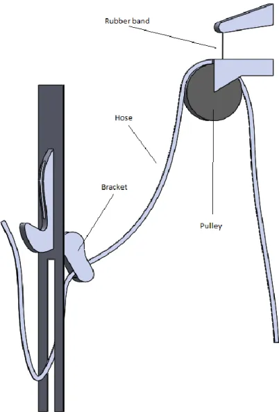
ROBLEM DESCRIPTIONHelix 6000 with a HHR hose retraction system is the fuel dispenser the concept will be implemented on. In the model the hose sits around a pulley, which in turn is attached to a rubber band as shown in figure 2. When the hose is being pulled the pulley goes down the rail it is attached to and the rubber band stretches. The further the hose is pulled out from its original state the more force is required to pull the hose. To ease the force required to pull the hose a new solution is desired.
2
Figure 2: This is an illustrating drawn model of the important parts of the current machine.
1.3 G
OAL AND SCOPEThe purpose of this thesis is to make the refueling process easier and prevent that refueling is not depending on strength. This means that a person in wheelchair may not have any kind of difficulty to refuel. The goal is to develop a product concept of a motorized hose handler which will reduce the amount of force required to pull the hose out. To reach the goal it is necessary to make a concept development and apply calculations and CAD on developed concept.
1.4 D
ELIMITATIONSThe study is demarcated to a concept study. There will be no reflections on the cost in terms of material choice or manufacturing. However, it will be considered in the initial concept choice stages to prevent major changes in the design. Any kind of climate effects will not be considered. The delimitation is to prevent the concept developing from being limited and to explore a wider space of concepts.
1.5 A
BOUT THE COMPANYWayneis a brand which is a part of Dover Fueling Solution (DFS). DFS provides their customers with end to end solutions with advanced fuel dispensing equipment. Wayne is one of two fuel dispenser
3
brands in the DFS-family. The Malmö plant has department both for design and production of dispensers. The company started 1891 in the US under the name Wayne Oil Tank Company. Their purpose were to build stable and reliable constructions for refueling. The first dispenser was developed in 1907 and since then the company has grown rapidly. The first office outside of the US was in Canada in 1919 and since then the company has expanded to England, Brazil, Australia, South Africa, Germany, Italy, Sweden and China. [4]
1.6 A
BOUT THE BRANDA man named Jakob Karl Ljungman, born in 1880 in Malmö, was the founder of J C Ljungmans plåt- och järnindustri that later became Waynes Fueling System Sweden. The former smith didn´t hesitate when the oil company Texacos boss asked to help out with a device that could distribute gasoline and started up the new company immediately. [5]
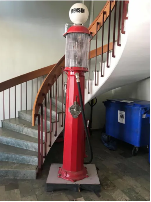
The first dispenser that released was named Fatos in 1924 and in that year one SEK gave five liters gasoline. The second one was named Tor and it could connect the tank below the surface. However, the first “real” dispenser came in 1927 and was named Vici, see figure 3. It had fixed outlet pipes for 5, 10, 15 and 20 liters, all this for the customers desire. It became a big seller all across the world and already after a year the factory had to expand to another location in Vellinge. In 1938, Jakob retired and died 1946. Erik Eklund took over as CEO in 1938. [5]
4
Figure 3: Vici fuel dispenser. Photo: Mikael Karlsson.
Erik Eklund took Ljungmans to a new era by moving the factory back to Malmö in Limhamn were a factory complex was built with modern facilities with office, workshops, molding and painting. The facility continued to grow and another facility was also build to support the production. In 1970, Eklund sold the company to Wayne which join the Dresser concern the same year. [5]
5
2 T
HEORY
In this chapter the theory used in this thesis is described. The theory is an important part to collect the knowledge around specific parts and guidelines to follow.
2.1 C
URRENT SOLUTIONThe current constructions regarding the hose handling consists of a rubber band connected to a pulley as shown in figure 2. The hose is hanging around the pulley so when the hose is pulled the pulley moves downwards and the rubber band is stretching. The rubber band will pull back the hose when there is no or too low force pulling the hose in the other direction. The rubber band makes the pulley move up to its original position. The pulley is attached to a rail which keep it steady when it moves up- or downwards. The bracket is spring loaded and assist the hose to maintain its position. Once the hose is pulled the bracket moves forward until it reached the wall of the dispenser. When the pulling force is released the bracket return to its original state.
2.2 S
CIENTIFIC ARTICLESStudying similar solutions to this project is important for inspiration. Scientific journals are valuable because it contains reliable content. Most of the solution made these days are inspired from something and studying scientific articles and similar papers can save a lot of time and prevent from “reinvent the wheel”.
2.2.1 Motorized seat belt system
The motorized seat belt (MSB) system is a safety system that protects passengers in car accidents. The system also checks the driving conditions before it decides a certain operation. For instance the belt tensions will act differently depending on which speed the vehicle is going. Furthermore, the system warns passengers if a dangerous situation occurs. The system is using sensors that initiate different operations. The system is driven with a DC motor which is analyzed with the MSB body on friction. There are some other parameters as well but the main focus is the friction’s impact. The friction determine how powerful the motor needs to be. [6]
This article is valuable for the project because of how the system controls the seat belt. When a person is refueling it is important that the motorized hose can handle both to be pulled out, and when the refueling is complete, also return to its original state. Measuring friction is also something that needs to be done in this thesis.
2.2.2 Argumentation and concept development: the role of imagination
This scientific journal dispute different concept development methods and highlights the importance of imagination. Following same methods that have been used for decades does not benefit the imagination. The article advocate instead of letting everyone speak free and not delimitate. The conclusion of the article is that as long the imagination is used freely, it will provide with the best development [7].
This journal is useful because the concept development is a big part of this thesis. Earlier courses have been strict with the methods which should be used. In this thesis however, some of the methods will be redesigned to benefit imagination.
6
2.3 ATEX
ATEX stands for explosive environment and is a classification on hazardous areas. In fuel dispenser, every single part must be ATEX-classified to be allowed sell the product. There are some different zones ranked in ATEX and three of them are important in this thesis. The zones are 0, 1 and 2. Zone 0 is the most explosive area and 2 the least. A typical area for zone 0 is inside the hose were it constantly or often contains fuel. On the dispenser, the hydraulic cabin is a zone 2 which means it is not expected or rarely any fuel. In the hydraulic cabin are all the electronic devices and motor would be suitable to be placed in there. For more information on ATEX, see Appendix A. [8]
2.4 S
ERVO CONTROLA servo control can be described as a function or a task. A power supply is connected to a programmable controller with low level power and a servo controller with high level power. A signal is issued from an interface panel to the positioning controller. It is a device which stores data with tasks and is programmed to activate motor, load or change speed. Then, the signal moves to the servo control. The low power signal increases and the power up to correct levels result in a movement in the motor. [8] [9]
The low power level signals needs to be amplified because higher voltage is necessary to rotate the servo motor when heavier loads are subjecting the motor. The controller gets feedback from the motor whether it needs more or less voltage. It is common that a load is driven around 900 rpm and the motor and controller support each other to maintain the speed. [8]
2.5 S
HRINK ASSEMBLYShrink assembly is a force conditioned action which is mainly a shaft and hub assembly. The assembly can be considered as permanent because it is near to impossible to disassemble. The main function is to transfer torque and axial force. The process is performed by using a shaft that is slightly bigger than the diameter of the hole of the hub. Then there are two alternatives to proceed. Either the hub is heated to expand the diameter of the hole, or the shaft is cooled which shrinks the shaft. When the heating or cooling process is done the assembly can be done, and furthermore, when the parts reach room temperature they become fixed and the assembly is completed.
3 T
ECHNICAL PROBLEM SOLVING
To develop a product there are several methods of doing this. In this thesis the Ulrich & Eppingers methodology is used [10]. Their methodology is a collection of different methods to develop a product in construction and design. This can be described by six phases as shown in figure 4: [11] [7]
Figure 4: Product developing phases. [9]
In the first phase, phase 0: Planning. A project description is made where goal, market, strategy and a time schedule is specified.
7
In phase 1: Concept development. Customers’ needs identifies, requirements specifies and concepts are developed and evaluated.
In phase 2: System level developing. Product architecture is being establishing.
In phase 3: Detail design. The geometry, material, tolerances and other details is specified. In phase 4: Testing and further developing. The concept is being tested with prototypes. In phase 5: Production. The product is produced in a small quantity at first to test the
production before it turns into producing greater quantities.
This thesis is about developing a concept and not a product and therefore not all steps in the methodology will be of use. In this study, the main focus is on phase 1, concept developing, which is a comprehensive phase and includes several steps. However, phase 0, 2 and phase 3 are also partly included. These methods are selected based on experience from other courses with product development as topic. For instance “Production Development Project” and “Applied design” [12] [13].
3.1 C
ONCEPT DEVELOPINGIn phase 1, the concept developing can be divided into five stages: problem description, seek externally, seek internally, explore systematically and reflection over stages, see figure 5. [10]
8
3.1.1 Problem description
The first stage is to clarify the problem in a detailed and defined way. Thereafter, the problem will be divided into sub problems and focus on the critical sub problems.
To create a better understanding of the problem it can be studied and analyzed and put in its relations to the development. To describe the problem a feature analyze can be used. The feature analyzes are a table consisting of the main, desired and necessary features of the concept. The features are described by a verb followed by a substantive, for instance “allow grip”.
Many problems are too complex to solve as one single problem and therefore it can be favorable to divide the problem into sub problems. The dividing process can be done repeatedly until every sub function is simple enough to work with.
3.1.2 Seek externally
The second stage is to seek externally and benchmark existing solutions and concepts that may be of interest for the study, which then can be used as inspirational sources to generate new concepts. This method is also for learning competitor solutions and find the advantage and disadvantage. [11]
3.1.3 Seek internally
The third stage is to seek internally which means the group submit what they already know. A common method for this is brainstorming which is one of many others. It is important to use several methods because the more methods that are used will increase the chance of finding the best concept.
Mind mapping is a method where keywords, ideas or phrases are used to generate words for solving the problem. The purpose is to generate as many words as possible and not to reflect or criticize any of the words. After all words are collected, the words are narrowed down to what is within the limit of possible. [14]
Brainstorming is a technique where the purpose is to reveal the creativity in a group. During the brainstorming it is important to not comment or judge any suggestions because it may disturb. As a topic for brainstorming it is usually a question of improving or what can be done.
There are some guidelines that can be followed for a successful brainstorming session [15]:
1. During the brainstorming the members of the group will state their ideas about the topic. Someone in the group writes keywords of all the ideas on paper so that everyone can see them. No name should be recorded on any of the ideas and no type of critic is allowed. It is encouraged to relate and extend other participants so that as many ideas as possible is collected. The session should not be longer than 30 minutes to maintain focus.
2. To make the ideal preparation the participants should be informed a week earlier about the topic and participants who never participated in a session before should receive an introduction. 3. The general rules say that the number of participant should not be more than twelve, be on the same hierarchical level, and include people who do not know anything about the problem area. The amount of time spent may be decided before the session begins, and it is important that conference room is a comfortable place to be in.
9
4. After brainstorming the follow-ups with judgment is not a part of brainstorming and other methods are used with experts in the field. Experts doesn’t necessarily need to be a part of the brainstorming.
A brainstorming can be done in several different ways. In this thesis the method is selected based on experience from previous courses at Malmö University [12] [13]. In this thesis, the brainstorming process will differ from the rules mentioned above in the way that critic will be allowed. This because the discussion from criticism is considered to provide different perspectives and may generate in new solutions.
Another method to seek internally is by using the gallery method. When using this method, the developing team shows different concepts at the same time and discuss them. Drawings of each concept is shown and explained, and the team can generate improvement or related concepts from it. This method is a good way to combine individual work and teamwork. [16]
3.1.4 Explore systematical
The fourth stage is to explore systematically. In this stage all sub problem concepts are tested with each other to find out what fits and what does not. For instance, if there are three sub problems and three great concepts for each problem but when the three concepts are combined together they do not work at all, and this is why this stage is important. [11]
Order policies is a method were the best concept is initiative selected for each sub problem. Verification is also done so that all sub concepts fit with one and another. A block diagram is recommended to do to illustrate how the sub concepts fits together and in which order they are. [10] Movement and provocation are used on the concept that the team intuitive selects as the best concept that have been presented from the order policies. The purpose with this is to stretch the limits and if it is successful it will generate new ideas that can contribute to the concept. Provocation can be performed in several different ways. These are the following ones that will be used for this project. [15]
Negation: In this provocation it is tested to remove an element from the product. For instance, it could be by removing a car seat and see if the car manage without it.
Inversion: Invert a situation from its normal situation. For example, a vacuum cleaner which is blowing instead of sucking.
Extreme cases: Normal values from different dimension are changed to extremely low or high. Distortion: This provocation is to change a normal order between different parts. For example,
by switching the place with a brick and a nut.
Wishful thinking: All about fantasizing of impossible things happen like having a wish or a vision.
10
Pugh’s scoring matrix is a method to decide which concept is best suited to solve a problem. Desired criteria for the concepts are determined within the group. The value of each criteria is determined depending on how important they are. The value of the criteria added together will be equivalent to one. All the concepts receive a grade depending on how well they fulfill the criteria. The grade will be multiplied with the value of the criteria and summed for all the concepts. The concept with the highest sum wins. [10]
A sensitivity analysis is a method to verify the stability of the concept. By changing the values on the different criteria in the scoring matrix and verify if the same concept is still the winner. Sometimes a more stable concept is better than a winner in a few cases. [17]
3.1.5 Reflection over stages
The fifth and last stages is reflection over the other stages. It is important to go through all the stages again to see if something is missing or wrong. Leaving too many problems behind will harm the results and a lot of work further on will probably be in vain. [11]
3.2 CAD
CAD, Computer-aided design, refers to the use of computers to create and analyze models of products. Solid work is an example of a CAD-program. In the software program, a 3D-model of a product can be sketched with exact measures and be used for illustrating the graphics of the product [18]. Blueprints can also be made in the program.
3.3 F
INITE ELEMENT METHODPhysical problems which are time- and space- dependent are often expressed in partial differential equations. In many cases with different geometries it is barely possible or would take many days, months or even years to solve with an analytical method. Instead, approximation of different equations can be done based on discretization. These methods will approximate the differential equations with numerical model equation which furthermore can be solved using numerical methods. The finite element method is used to solve these kinds of approximations. [19]
3.4 S
TATICC
ALCULATIONIn this chapter the calculations regarding the force on the bracket and the motor torque is calculated. The chapter also presents which type of equations are used.
3.4.1 Force
To determine an unknown force in a system an equation system can be set up where all vertical forces are putt in one equation and all horizontal forces on a second equation. The torque is putt in a third equation. With all three equation, up to three unknown forces can be determined with this method. [20]
11
3.4.2 Motor toque
A motor that can provide enough torque is required to pull the hose. The torque M is calculated as shown in equation 1 were the force needed to pull the hose is denoted with F and the length of the route from the center of the motor shaft to the rollers surface is denoted with L.
𝑀 = 𝐹 ∙ 𝐿 (1)
3.5 C
OMPONENTS AND MATERIAL OF CHOICECES EduPack is a software for gathering material data [21]. CES EduPack is a set with material data supported of scientific research. The software contains a lot of materials and alloys which can be put in different charts were many different topic can be used. For instance the Young´s modulus versus density. Furthermore, it is possible to apply limits which removes undesired materials, for instance a limit can be applied that remove all flammable materials.
12
4 P
ERFORMANCE
The performance chapter describes how all the methods are used and applied on the concept study. This is the buildup that will lay the ground for the result.
4.1 C
HOICE OF CONCEPTTo develop the concept that is best suited to solve the problem, there are some different methods that are used as described in section 3. In this chapter it is explained how the methods are used.
4.1.1 Problem description
A feature analyze is made to get an understanding of the problem, see table 1. The features are described by a verb followed by a substantive and classified as main, necessary and desired features. The functions are classified as: main function (MF), desired function (DF) and necessary function (NF). The main function is to allow hose handling, this is the function that other function needs to adapt to and cannot be dismissed. To satisfy the customers the concept is desired to be user friendly. It is necessary that service can be done on the concept if there is something that needs to be corrected or repaired. The fuel dispenser has a limited amount of space and there might be other concepts later that needs to be implemented, therefore, the space of the concept is desired to be minimized. To prevent any kind of complication and reduce cost, the changes to the current construction is desired to be minimal. The fuel concept needs a lifetime of 10 years or more. Therefore the sustainability is necessary to be maximized and needs to withstand wear and tear. It is desired that the concept can be regulated if there is something that needs to be changed. Since the fuel dispenser operates in a hazardous environment the concept need to follow the ATEX certifications, see appendix A.
13
Table 1: The table present the different functions the concept should have and is classed as a main-, desired- or necessary function.
Function Class Remark
allow hose handling MF
maximize user-friendly DF
allow service ability NF
minimize space DF
minimize changes DF current construction
maximize sustainability NF
withstand wear and tear NF
offer regulation DF
own ATEX-certification N F
4.1.2 Seek externally
The following different concepts are studied and used as sources of inspiration.
To extinguish fire a water hose roller is used by firefighters. The hose roller can either be manual or motorized. The hose is reeled on a wheel and is unreeled when the wheel is spinning clockwise and reeled in when the wheel is spinning counterclockwise, see figure 6.
14
Another possible solution to control the different hoses is to use the same solution as in cars with the gearbox, see figure 7. The countershaft and main shaft connects with different gears depending on which gear in the gearbox is chosen. The gears function is to transmit power from one shaft to another. To apply this method to the hose handling one gear can be used for each hose, and when one of the hoses are pulled the gear connects with a main gear which is connected to the motor. [22]
Figure 7: The figure shows the gears in a motor [22].
The ski lift technique is a simple and an effective transportation. There are two big wheels at the beginning and the end of the lift, with engines that drives the cable, see figure 8. The chairlift has a fixed mechanic grip with a similar function as a vice when it connects with the cable. A mechanical grip applied to the hoses may not work, but by using sensors which initiate which one of the hoses that are used and then execute the grip is a possible solution for this concept. [23]
15
Figure 8: The red big wheel is connected with a motor that drives the cable [24].
4.1.3 Seek internally
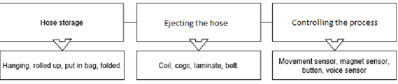
The main problem is managing the hose, which is divided into the sub problems: storing the hose, ejecting the hose and controlling the process. Mind mapping is performed with the input from the sub problem division as keywords. The mapping is narrowed down to four ideas to build a concept on, see figure 9.
Figure 9: Mind mapping.
The brainstorming session is performed based on the topics from the mind mapping session and the benchmarking research that were preformed earlier. The different words of use is hose storage, ejecting the hose, controlling the process and placement.
The first concept is similar to a cars gearbox. The idea is that all the hoses have their own cogwheel connected instead of the pulley. When one of the hoses is pulled, that particular hose cogwheel is pulled down to the motor, which connects with another cogwheel from the motor and then it runs as the hose is stretched. No solution to pull back the hose is discussed.
The second concept is a driving belt which works a bit like the first concept. When one hose is pulled it connects to the belt and the friction makes the hose advance forward. The friction can also be used to pull back the hose in the dispenser again but the better solution would be to keep using the rubber band that’s already in the dispenser.
16
The third concept is inspired from a fire extinguisher hose. If all the hoses are rolled up as figure 6 a motor could drive the wheels that the hoses are rolled up to. It is a simple concept and it is discussed about a sensor on the bracket were the nozzle is placed. The bracket tilts when the hose is pulled so a sensor there could be useful.
It is also discussed where the motor should be placed and it is decided that is should be in the hydraulic cabin that is placed next to the hose cabin were the other electronic parts is stored. In the hydraulic cabin the motor is protected from fuel and access to electricity. But further accurate placement is not decided and will not be during the thesis because it would take too much time from the main objective. After the brainstorming the gallery method is applied on the different concepts. Two engineers at Wayne´s joined the session to generate ideas. On the concept with cogs a suggestion is to use the cogs near the bracket instead of beneath the pulley.
On the fire extinguisher concept, the idea of using rotation springs to pull back the hose. It is also discussed how the system will know when it´s time for ejection or pulling back the hose. Sensors at the bracket when it tilts and when the nozzle is removed or laid back again in the nozzle boot, there are two options of placing a sensor that will initiate the process.
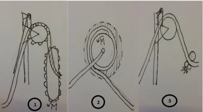
The tree different concept from the gallery method are illustrated in figure 10.
Concept 1: When the hose is being pulled the pulley connects to the motorized belt and the motor starts spinning the belt. As long as the hose is pulled the belt continues to spin until it’s in the maximal position. The motor then stops and waits until the user has refilled. When the refueling is completed the motor starts again and pulls the hose back to its original position. Concept 2: The concept is inspired by fire extinguisher hose. The idea is that instead of the
current construction with a pulley, the hose is instead wrapped around wheel. When the hose is being pulled the motor starts and roll out the hose. As long as the hose is pulled the motor rolls out the hose. When the user has refilled, the motor rolls in the hose.
Concept 3: The third concept is inspired of lamination and ski lifts. The idea is that the rollers are used to move the hose forward. When a particular hose is pulled it will connect with the roller and the motor starts. It will be one roller at each hose and because there needs to be just one motor, all the rollers will spin when one hose is pulled. The rollers will be put on the same shaft, but they will only connect with the hose if their particular hose is being pulled. When it is time to put back the nozzle the roller will release from the hose and the rubber band which is currently in the dispenser will bring back the hose in its original state.
17
Figure 10: The figure shows the tree different concepts from the mind mapping.
4.1.4 Explore systematical
The order policy method is used to determine a concept for each sub problem. To store the hose the concept which includes hanging is selected as the favorite concept. To eject the hose a driven belt will be used and movement sensors to initiate the processes. All the parts are dependent on each other working together. The movement sensor could possibly be replaced, however it would only make the process more complicated. For instance, if it was done with a timer it could do more harm than good for the user.
With the mind mapping and brainstorming as a starting point, movement and provocation is used to create more concepts. The first test is to change the belt to a wheel which is driven the same way as the belt. An extreme case would be to make the belt much smaller which would create a lot of more space in the pump. One other extreme case would be to put a lot of movement sensors in the pump. Too many would be unnecessary however a few extra could be helpful because of the many stages during the refueling process.
Two of the ideas came from the next stage of the concept selection. The first is the one to make the belt much smaller because the lack of space in the pump and the other is to use more movement sensors. There are still some gaps in the concept, for instance when the hose knows when it is time to pull back and with more movement sensors this could be solved.
A matrix is made to show how well the different concepts fulfills the criteria as shown in table 2. The criteria is decided based on experience and discussion with the engineers at Wayne´s. The criteria usability and price is valued highest. Usability is given a value of 0,4 and price a value of 0,3. Maintenance, space and adjustment is valued low and is given a value of 0,1. Each concept is graded from a scale to 1-5 depending on how well they fulfill the criteria. The grades is multiplied with the criteria value and summed. The winner is not the one selected in the order policy. These methods helped to pick the best concept because the lack of space was considered more during this method than movement and provocation method.
18
Table 2: Pughs scoring matrix. Criteria and value Concept 1 Concept 2 Concept 3
Usability (0.4) 3 4 4 Price (0.3) 2 4 5 Maintenance (0.1) 4 1 2 Space (0.1) 1 2 5 Adjustment (0.1) 3 3 3 Sum 2,6 3,4 4,1
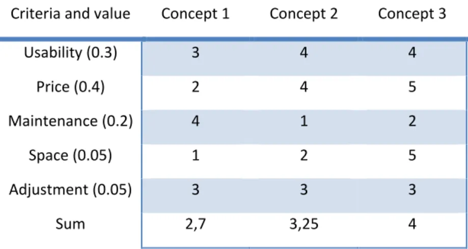
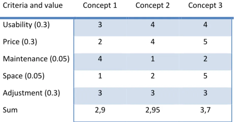
After re-adjusting some of the criteria with a sensitivity analysis the result became a little different although same place remains, see table 3 and 4. Two different set valuation is made to test the stability of the concepts. Concept 3 is without doubt the best fitted but concept 1 is most stable. If it had been closer in terms of scores it may have been the winner, but the winning concept is concept 3.
Table 3: Readjusted criteria matrix also known as sensitivity analysis. Criteria and value Concept 1 Concept 2 Concept 3
Usability (0.3) 3 4 4 Price (0.4) 2 4 5 Maintenance (0.2) 4 1 2 Space (0.05) 1 2 5 Adjustment (0.05) 3 3 3 Sum 2,7 3,25 4
19
Table 4: Another sensitivity analysis. Criteria and value Concept 1 Concept 2 Concept 3
Usability (0.3) 3 4 4 Price (0.3) 2 4 5 Maintenance (0.05) 4 1 2 Space (0.05) 1 2 5 Adjustment (0.3) 3 3 3 Sum 2,9 2,95 3,7
4.1.5 Presentation of the chosen concept
Concept 3 is the concept that is chosen. In concept 3, the motor starts when a hose is pulled and connects to a roll which is pressing on the hose and starts to rotate which makes hose advance forward. When the user is done refueling the rolls release its pressure and the rubber band pulls back the hose to its original state. The rollers use friction to bring the hose forward.
4.1.6 Further development of chosen concept
The concept choice is made but all details are not yet decided. Therefore, another gallery method is done on the concept to determine more in detail how it is going to work. Four engineers working at Wayne are invited to join the brainstorming. A small presentation is done to update the invited engineer’s about concept 3 in figure 11 and the topics that needs to be discussed in the gallery method. The gallery method in this session was divided in three parts.
The first part where to discuss about when the hose handler initiates the different actions. The problem for the hose handler is to know whether it is time to eject or pull back the hose. An idea came up were the ejection starts when the hose is pulled which is activated by a sensor. The motor stops when the user stops pulling the hose. The hose is being pulled back by the rubber band when the nozzle is returned to the nozzle boot.
The second topic is about the placement of the rollers. Because of the limited space one idea is to place the rollers under the nozzle boot.
The third topic is concerning the connection between the hose and the rollers. An idea is that when the hose is being pulled the bracket tilts and when it is tilted it will be locked to that state and the hose is being pressed to the rollers by the bracket. With this concept it will only be the hose that is pulled which connects with rollers. The different states are shown in figure 11.
20
Figure 11: The figure illustrates the two states, state one were the hose is at rest and state two were the hose is being pulled.
4.2 CAD
With the software Solid Works all the different objects are made in a 3D graphical view. Blueprints are also made for all objects. Measurements are made on the dispenser to make sure that all the parts would fit in and got the correct measures.
4.2.1 Shafts stand
The shafts stand is made for keeping the shaft steady and prevent vibrations. The shaft stand is modeled in 3D, see appendix B.
4.2.2 Shaft
The shaft will be in different lengths depending on how many hoses are connected to the particular dispenser. In this case it is made for a dispenser with three hoses on each side. No further details are made for the shaft because the assembling with the rollers will be made with shrink assembling. The stand is modeled in 3D, see appendix B.
4.3 F
INITE ELEMENT CALCULATIONCalculations are made in Solid works simulation tool. Each components, i.e. material, boundary condition and acting forces, specified.
21
The shaft with the rollers is specified as fix in the ends and the force acting on each roller is set to 5 N which is the force the bracket presses the hose against the rollers. The calculation is made to
determine if the effective tension in the shaft is higher than the yield strength of the component. The maximum effective tension is calculated to 7.182×10³ N/m2 and the yield strength is 6.204 ×10⁸ N/m2. The simulation is presented in figure 12.
Figure 12: FEM analyses on shaft with rollers.
The shaft stand is specified as fixed in the bottom of the stand and the force acting on the stand is the mass from the shaft. The acting force is set to 1 N. The calculation is done to determine if the effective tension in the stand is greater than the yield strength of the component. The maximum effective tension is calculated to 1.801×10³ N/m2 and the yield strength is 6.204 ×10⁸ N/m2. The simulation is presented in figure 13.
22
Figure 13: FEM analyses on shaft stand.
4.4 S
TATICC
ALCULATIONIn this chapter the calculations regarding the force on the bracket and the motor torque is calculated. The chapter also presents which type of equations is used.
4.4.1 Force
For the motor to be able to drive the hose forward the rollers needs to be pressed on the hose with a certain amount of force, or else the friction force acting between the hose and the roller will be too small and the hose will just slip. The rollers normal force acting on the hose is denoted with t, the
23
friction force between the rollers and the hose is denoted witch f and the force that is withdrawing the hose is denoted with S.
Figure 14: Model of hose with acting forces. .
An equilibrium is set up to determine the normal force t as shown in equation 2.
→: 𝑆 − 2𝑓 = 0 (2)
The friction force f is calculated as shown in equation 3 were the static friction coefficient is denoted by µs.
𝑓 = 𝑡 × µ𝑠 (3)
With the expression for the friction force and equation 2 the equation can be set up as in equation 4 to solve for the normal force t.
𝑡 = 𝑆
2µ (4)
4.5 M
ATERIAL SELECTIONTo select the best possible material for the rollers Edupack is used. The rollers need to transfer a force of friction on the hose, therefore a material type with a high friction coefficient against the rubber hose is selected. Elastomers and polymers is chosen because of its generally high friction which will prevent any slipping between the hose and rollers [24]. Since the material will be used in a fuel dispenser there are requirements which must be taken into account concerning the selection of materials, see appendix A about ATEX. Within EduPack a diagram is made with Young´s modulus versus density since the material needs to be stiff to drive the hose forward and light to not exert the axel with any unnecessary weight. A filter is used were minimal and maximum service temperature is set to -40⁰C versus +70⁰C and were the durability with fuel is set to accepted. The chart for the polymers is shown in figure 15 and a chart for the elastomers is shown in figure 16.
The material that were chosen is Polyurethane as the best possible material for the rollers is Polyurethane because of its high young’s module and low density.
24
Figure 15: Chart of polymers [21].
Figure 16: Chart of elastomers [21].
When selecting a material for the shaft and the stand the materials is plotted in a diagram with young’s modulus versus density, since the components needs a stiff and light character. The same criteria’s as for the rollers is applied regarding ATEX and temperature. The materials are presented in figure 17. The material that is selected from the material chart is stainless steel because it’s the material that accepted based on the criteria’s.
25
Figure 17: Chart of materials for shaft and stand [21].
4.6 M
OTORWhen selecting the motor a force gauge is used to measure force required to pull the hose, see figure 18. The force gauge presents that when the hose is pulled out to its limit, the force to maintain the nozzle is 90 N.
26
Figure 18: Measuring the force on the hose with a force gauge.
From the result the required torque is calculated. With the force 90 N and the length 0.035m inserted in equation 1 the required torque is 3.15 Nm.
4.7 S
ELECTION OF SERVO CONTROLLERDepending on the placement of the motor and in which ATEX zone (see Apendix A) it is placed in there are certain requirements regarding the servo controller. In the fuel dispenser all possible locations were the motor can be placed is in Zone 0, 1 and 2. Zone 0 is an area in which an explosive mixture of gas, steam or fog in air occurs constantly or prolonged and is the zone where there is the highest risk of explosion. Since the placement either is in Zone 0, 1 or 2 the motor have to be ATEX classified and function in an explosive environment.
The motor selected is an ATEX classified servo motor which is designed for use in explosive environment and is called Ex-series explosion proof (ATEX) brushless servo motors. Two different version are available and the difference are the US or European safety standards are required, see Appendix C. [25]
27
5 R
ESULT
The resulting concept is a shaft with rollers in front of each bracket. The rollers are made of Polyurethane and the shaft of stainless steel. When a hose is pulled the bracket will connect the hose with a roller and the shaft starts to rotate. Small bars have been applied under each hose to prevent the hoses from laying on the rollers. This is to prevent any sliding damage on rollers and hoses while they are not in use. The shaft will only rotate as long as the hose is being pulled. Once there is no pulling force the shaft stops to rotate and stands on a fix state which will prevent the force from the rubber band to bring back the hose. Further, when it is time to put back the nozzle, the bracket will release the hose from the rollers once the hose is no longer stretched out and the rubber band will assist the user to bring back the hose in its original position.
Figures 19 and 20 represent how the concept is adapted to the dispenser from different angles.
28
Figure 20: Hose ejection side view.
Figure 21 and figure 22 presents the concept when it is not integrated with the fuel dispenser. The model is only presented as an illustrating model of the concept and further testing would be required to determine its set up and placement. The motor drives the shaft that is held up by stands and bearings. On the shaft the rollers are mounted by shrink assembling.
29
30
31
6 D
ISCUSSION
The development of the hose handler concept resulted in rollers connected to a shaft that is driven with a servo motor. The shaft is held up with stands and all the parts have calculated basis to proceed with. The concept was developed with reliable product development sources. In reality it is possible that something will not work properly and further testing is necessary to approve or adjust the reliability of the concept.
The placement of the motor is one thing to study more closely for this concept in the future. The problem is to make it fit and still be powerful enough to spin the shaft.
It was decided early in this study that a servo control should be selected as a motor. No investigation of other alternatives were made because this was not the main objective. There are more possibilities with a servo control compared to a regular motor in terms of coding and steering with precision. However, this concept could have been cheaper if a concept with a regular motor were used instead. The technical problem solving is a time consuming process and important. This study has created a lot of ideas however it might not have been the best methods for this thesis. In previous courses when there is just a group of students creating a concept by themselves with no external help, it is recommended to use this method. However, in this study there is a lot of external help such as the staff at Wayne´s which have been helpful and valuable for this thesis. These methods have tied up the study a bit of instead go directly to the staff and ask for their opinion. Some of the ideas that were brought up and not good enough but still followed through the methods could have been removed earlier by an employee.
The desire from Wayne´s about just using one motor for five hoses made the process a lot more challenging. With one motor for each hose it would have been much easier to apply different concept. But what´s positive with this demand is more creativity has been developed and a lot of experience has been gained which it probably not been if more simple concept was done.
The resulting concept was obtained much because it was easier to apply than the other concept. This concept is depending on high friction and if it is not high enough then it will damage the hose and the rollers if it slides instead of rolling. The other concepts were less dependent on such matters however the costs would be greater than the winning concept.
The stands for the shaft could have been more optimized than they were. Finite element analyses was done to make compare the effective tension and the yield strength. The measurements were just made to fit with the shaft and also assured to fit in the small space. However, to spare material and weight, it could have been possible to make the stand less thick or make a framework construction.
The small bars which were mounted on the dispenser to prevent the hoses laying on the rollers can be a problem if the concept is tested. The hose may be too stiff were the nozzle is and can cause the nozzle to fall out of its position. This was detected too late in the project and this is the disadvantage when no physical parts are acquired. A solution for this could be to place the shaft further away from the nozzle.
One of the delimitations in the thesis is that there will be no reflections on the amount of cost in terms of material choice or manufacturing. This is something that will be of importance if Wayne choose to proceed with the concept.
32
7 C
ONCLUSION
In this project a concept of a motorized hose handler have been developed for the brand Wayne Fueling Solutions Sweden AB. The concept consist of rollers on a shaft driven by a servo controller. The shaft is sustained with stands between each hose. When one of the hoses is pulled the hose gets pressed against the rollers and the motor starts which makes the hose to eject. When the operator stops pulling the hose, the motor will maintain the hose in the same position. Further when the nozzle is brought back to the nozzle boot the hose releases from the roller and the hose is pulled back assisted by the rubber band which each hose is connected to inside the dispenser.
The conclusion is that it is fully possible to make a motorized hose handler to a dispenser with just one motor to each side. Materials that follows ATEX standards are selected and calculations insure that the constructions which are drawn withstands their purpose. The concept has been developed with reliable research which for instance is used in multiple courses in Malmö University. There is still more details in terms of motor placement and testing that is required before this concept can be made into a product. What the company does with this concept is yet for them to decide.
33
R
EFERENCES
[1] ”Svenska Peotroleum & Biodrivmedel Institutet,” [Online]. Available: http://spbi.se/statistik/forsaljningsstallen/. [Använd 22 03 2018]. [2] E. Blom, ”Handelns historia,” [Online]. Available:
http://www.handelnshistoria.se/historien/olika-sorters-handel/bensinhandel/. [Använd 22 03 2018].
[3] ”Wayne.,” 2018. [Online]. Available: https://wayne.com/en/products/. [Använd 05 07 2018]. [4] ”Our history,” 2017. [Online]. Available: https://www.wayne.com/en/about/.
[5] M. Andersson, ”Så blev Ljungmans bensinpumpar en storindustri i Malmö,” Sydsvenskan, 2017. [6] K. Lee och W. Lee, ”State estimation for motorized seat belt system using sliding-mode
observer,” International Journal of Automotive Technology , vol. 13, pp. 301-308, 2015. [7] A. Larraín, ”Argumentation and Concept Development: The Role of Imagination.,” European
Journal of Psychology of Education, vol. 32, nr 16, p. 16, 2017 .
[8] A. S. I. I. SIN, ”Sini,” 01 2012. [Online]. Available: http://www.sini.se/marknad/teknisk-info/153001.pdf. [Använd 05 07 2018].
[9] ”Servo control facts,” [Online]. Available: http://www.baldor.com/Shared/manuals/1205-394.pdf. [Använd 10 02 2018].
[10] S. Sugiyama, ”Multi-Stage PWM DC Servo Motor Control,” IFAC Proceedings Volumes, vol. 22, nr 18, pp. 341-345, 1989.
[11] K. T. Ulrich och S. D. Eppinger, ”Produktutveckling, konstruktion och design,” Studentlitteratur
AB, 2014.
[12] P. Gerhard, B. Wolfgang och J. a. G. Feldhusen, ”Engineering Design,” 2007.
[13] M. Fisk, ”Malmö universitet,” [Online]. Available: https://edu.mah.se/sv/Course/PD131A. [Använd 04 05 2018].
[14] M. Fisk, ”Malmö universitet,” [Online]. Available: https://edu.mah.se/sv/Course/MT119A. [Använd 04 05 2018].
[15] J. Michanek och A. Breiler, ”Idéagenten: En handbok i idea management,” BookHouse Editions, 2007.
[16] E. d. Bono, ”Verklig kreativitet-Använd lateralt tänkande för att skapa nya idéer,” Brain Books
34
[17] C. Terwiesch och K. T. Ulrich, ”Innovation Tournaments: Creating and selecting Exceptional Opportunities,” Harvard Business Press, 2009.
[18] ”Känslighetsanalys vid invensteringskalkylering,” Bokföringstips, 08 02 2010. [Online]. Available: http://www.bokforingstips.se/artikel/ekonomistyrning/kanslighetsanalys-investering.aspx. [Använd 22 02 2018].
[19] ”Solidworks,” Dassult Systèmes. [Online]. [Använd 26 01 2018].
[20] ”Comsol,” [Online]. Available: https://www.comsol.com/multiphysics/finite-element-method. [Använd 25 03 2018].
[21] O. Dahlbom och K.-G. Olsson, ”Strukturmekanik,” 2010. [22] G. Design, CES Edu-Pack, 2016.
[23] ”What is gear box? What are main components of gear box?,” Mech4study, 31 03 2014. [Online]. Available: http://www.mech4study.com/2014/03/what-is-gear-box-what-are-main-components-of-gear-box.html. [Använd 16 02 2018].
[24] A. J. DD Tomatos, ”How does a chairlift work?,” UnofficialNetworks, 23 11 2013. [Online]. Available: http://unofficialnetworks.com/2013/11/23/chairlift-work/. [Använd 16 02 2018]. [25] ”The engineering toolbox,” [Online]. Available:
https://www.engineeringtoolbox.com/friction-coefficients-d_778.html. [Använd 28 03 2018].
[26] ”EX-SERIES EXPLOSION PROOF (ATEX) BRUSHLESS SERVO MOTORS,” Parker, [Online]. Available: http://ph.parker.com/us/17607/en/ex-series-explosion-proof-atex-brushless-servo-motors. [Använd 08 05 2018].
[27] ”Räddningsverkets handbok om explosionsfarlig miljö vid hantering av brandfarliga gaser och vätskor,” Räddningsverket, 2004.
[28] ”Rubber chemical resistance chart,” Mykin inc., [Online]. Available: http://mykin.com/rubber-chemical-resistance-chart. [Använd 05 04 2018].
[29] Annca, Artist, Sky lift. [Art]. 2015.
[30] Anca-gear, ”pixabay.org,” [Online]. Available: https://pixabay.com/sv/motorfordon-%C3%B6verf%C3%B6ring-upp-1381995/. [Använd 18 04 2018].
[31] Anca-hose, ”pixabay.com,” [Online]. Available: https://pixabay.com/sv/brandk%C3%A5ren-brandslangar-tank-2736623/. [Använd 18 04 2018].
[32] A. lift, ”Sky,” Pixaby, [Online]. Available: https://pixabay.com/sv/skidlift-transport-skilift-wheel-2000597/. [Använd 18 04 2018].
a
A
PPENDIX
A,
ATEX
ATEX means atmosphere explosives and is about classification of hazardous areas.
An explosive atmosphere is a mixture under atmospheric consisting of air and burnable material in form of gas, steam, fog or burnable dust in which the ignition spreads to all of the unburned mixture. An explosive area is an area were a hazardous mixture consisting of gas, steam, fog or dust together with air consists. The hazardous areas are divided into different zones depending on frequency and duration of an explosive atmosphere. [8]
ZONE 0: An area in which an explosive mixture of gas, steam or fog in air occurs constantly or prolonged. Very high risk.
ZONE 1: An area in which an explosive mixture of gas, steam or fog in air is expected to occurs during handling. High risk.
ZONE 2: An area in which an explosive mixture of gas, steam or fog in air is not expected to occurs during normal handling, and if it does occur, if so, only rarely and shortly. Low risk.
ZONE 20: An area in which an explosive mixture of dust in air occurs constantly or prolonged. Very high risk.
ZONE 21: An area in which an explosive mixture of dust in air is expected to occur during handling. High risk.
ZONE 22: An area in which an explosive mixture of dust in air is not expected to occur during normal handling and if it does occur, if so, only rarely and shortly. Low risk.
Gas and dust is divided into different groups depending on the type of gas or dust. The categories define which zones the devices may be used in as shown in Table 6.
Table 5: Material groups with different explosive mixture that is divided into ZONE, group and category.
Material group Explosive mixture ZONE Group Category
Gas, steam, fog
Occurs constantly or prolonged ZONE 0 II 1G Expected to occur when handling ZONE 1 II 2G Not expected to occur, if so, only rarely
and shortly
ZONE 2 II 3G
Dust
Occurs constantly or prolonged ZONE 20 II 1D Expected to occur when handling ZONE 21 II 2D Not expected to occur, if so, only rarely
and shortly
ZONE 22 II 3D
b Methane(mining)
Potentially explosive area - - M2
Burnable gases are divided into risk groups as shown in Table 6. Group І refers only to methane-air mixture in mines. Group ІІ are divide into subgroups depending on gas mixture. Were IIA is the lowest risk group and IIC the highest.
Table 6: Burnable gases divided into riskgrups. Group ІІ (mines) І Gas Methane Group ІІ ІІA Gas Propane ІІB Ethylene ІІB + H2 Ethylene + hydrogen ІІC Acetylene + hydrogen
Burnable materials is divided into temperature classes as shown in Table 7. The class from T1-T6 depends on the materials ignition temperature. Thus the lowest temperature on the surface of an instrument at which the material self-ignite in contact with the surface. This refers only to gas atmosphere.
Table 7: Diffrent temperatured divided into classes.
Class T1 T2 T3 T4 T5 T6
c
A
PPENDIX
B,
CAD
MODULES AND DRAWINGS
d
e
f
g
h
![Figure 1: This is the Helix 6000, this is the dispenser the concept is applied on [3]](https://thumb-eu.123doks.com/thumbv2/5dokorg/4072082.84857/8.892.269.617.508.1059/figure-helix-dispenser-concept-applied.webp)
![Figure 5: Concept developing process. [9]](https://thumb-eu.123doks.com/thumbv2/5dokorg/4072082.84857/15.892.140.779.532.1086/figure-concept-developing-process.webp)

![Figure 7: The figure shows the gears in a motor [22].](https://thumb-eu.123doks.com/thumbv2/5dokorg/4072082.84857/22.892.106.797.235.660/figure-figure-shows-gears-motor.webp)