V¨
aster˚
as, Sweden
Thesis for the Degree of Bachelor of Science in Engineering
-Computer Network Engineering 15.0 hp
DESIGNING A LAB ASSIGNMENT
FOR STUDYING REAL-TIME
EMBEDDED SYSTEMS
Rasmus R¨
annar
rrr15002@student.mdh.se
Miika Mustaniemi
mmi15001@student.mdh.se
Examiner:
Elisabeth Uhlemann
M¨
alardalen University, V¨
aster˚
as, Sweden
Supervisor: Elena Lisova
M¨
alardalen University, V¨
aster˚
as, Sweden
Abstract
Embedded systems are all around us in the modern world and continue to evolve as time passes. Therefore, it is important to keep the knowledge in the field evolving, and education is a big part of it. This thesis focuses on how to design a lab assignment for a course about embedded systems with the stress on networking. Embedded systems have reliability and timeliness requirements, which will have to be accounted for when designing the network of the system. The work started with a literature study of communication protocols and how they support the requirements imposed by the embedded systems. Using this knowledge hardware was evaluated and chosen. With the lab assignment in mind, Arduino Zero was chosen as the platform as well as three network modules: Wi-Fi, Bluetooth and Zigbee. The hardware was used to implement a simple embedded system consisting of two nodes: a sensor node and a controller node. The sensor node sends the data to the controller which then acts upon the data. Three program were written, each with its own communication solution (time-triggered, event-triggered and a hybrid solution) and then tested in different environments. From the results of the tests, guidelines were formulated about how to design an assignment and what hardware to use. A general guideline was also created describing a lab assignment step by step. We recommended switching the platform from Arduino Zero to Arduino Uno to reduce the amount of workarounds needed to get the system running. Having more than one communication protocol also proved valuable since the students could show their knowledge by argumenting for their choice of protocol.
Table of Contents
1. Introduction 1
1.1 Problem formulation . . . 2
2. Real-time Communication 3 2.1 Real-time Embedded Systems . . . 3
2.2 Real-time Operating Systems . . . 4
2.3 Communication for Real-time Embedded Systems . . . 4
2.3.1 IEEE 802.11 . . . 5 2.3.2 Cellular communication . . . 6 2.3.3 IEEE 802.15.1 . . . 7 2.3.4 IEEE 802.15.4 . . . 9 3. Related Work 11 4. Method 12 5. Design and implementation of the lab assignment 13 5.1 Hardware . . . 13 5.1.1 Raspberry Pi . . . 13 5.1.2 Arduino . . . 13 5.1.3 Texas Instruments . . . 14 5.1.4 Selection of platform . . . 14 5.2 RTOS . . . 14 5.3 Testing setup . . . 15 5.3.1 Controller node . . . 15 5.3.2 Sensor node . . . 16 5.3.3 Communication setup . . . 17 5.3.4 Time synchronization . . . 17 5.3.5 Types of programs . . . 18
5.3.6 Test environment setup . . . 19
5.4 Testing procedure . . . 19
6. Results 21 6.1 Wi-Fi . . . 21
6.2 Bluetooth . . . 24
6.3 Zigbee . . . 27
7. Lab assignment guidelines 30 7.1 Hardware choices . . . 30
7.1.1 Limitations of the network modules . . . 30
7.2 Communication protocol proposition . . . 31
7.3 Possible pitfalls . . . 31
7.3.1 Problems reading serial data . . . 31
7.3.2 RTOS priorites and serial communication . . . 31
7.3.3 The micros function . . . 31
8. Discussion 32
List of Figures
1 Spectrum of real-time systems . . . 3
2 Simplified view of the communication cycle for PCF. Each contention free period is started with a beacon message (B) and ends with a CF-END message. . . 6
3 Bluetooth topology. . . 8
4 Basic Bluetooth communication. . . 8
5 802.15.4 Communication cycle on a beacon enabled network. . . 9
6 Visualization of the research process. . . 12
7 Fully assembled controller node. . . 16
8 Fully assembled sensor node. . . 16
9 Time stamps of the offset calculation. . . 18
10 Model of how the delay was measured. . . 20
11 Results for the time-triggered Wi-Fi solution. . . 21
12 Results for the event-triggered Wi-Fi based solution. . . 22
13 Results for the hybrid Wi-Fi based solution. . . 23
14 Results for the time-triggered Bluetooth based solution. . . 24
15 Results for the event-triggered Bluetooth based solution. . . 25
16 Results for the hybrid Bluetooth based solution. . . 26
17 Results for the time-triggered ZigBee based solution. . . 27
18 Results for the event-triggered ZigBee based solution. . . 28
19 Results for the hybrid ZigBee based solution. . . 29
List of Tables
1 Criteria for protocol properties evaluation. . . 52 Comparison of platforms. . . 14
3 Packet delays in ms for time-triggered Wi-Fi. . . 21
4 Time synchronization offsets during time-triggered Wi-Fi testing in ms. . . 22
5 Packet delays in ms for event-triggered Wi-Fi. . . 22
6 Time synchronization offsets during event-triggered Wi-Fi testing in ms. . . 23
7 Packet delays in ms for hybrid Wi-Fi. . . 23
8 Time synchronization offsets during hybrid Wi-Fi testing in ms. . . 23
9 Packet delays in ms for time-triggered Bluetooth. . . 24
10 Time synchronization offsets during time-triggered Bluetooth testing in ms. . . 25
11 Packet delays in ms for event-triggered Bluetooth. . . 25
12 Time synchronization offsets during event-triggered Bluetooth testing in ms. . . 25
13 Packet delays in ms for hybrid Bluetooth. . . 26
14 Time synchronization offsets during hybrid Bluetooth testing in ms. . . 26
15 Packet delays in ms for time-triggered ZigBee. . . 27
16 Time synchronization offsets during time-triggered Zigbee testing in ms. . . 27
17 Packet delays in ms for event-triggered ZigBee. . . 28
18 Time synchronization offsets during event-triggered Zigbee testing. . . 28
19 Packet delays in ms for hybrid ZigBee. . . 29
1.
Introduction
Embedded systems refer to a system designed to do one specific task and which is often part of a larger system [1]. These systems are all around us in the modern world e.g., in the cars we drive or in the smartphones we carry in our pockets. With the recent introduction of Internet of Things, the market for embedded systems is expected to increase, though the rate of growth and market size is disputed1,2. Without embedded systems devices like smart fridges or smart dishwashers would not function. Many embedded systems are also real-time systems. They not only have to perform a task they are designed to do, they also have to do it within a specified time range [2]. Some embedded systems do not operate in isolation and have to communicate with other embedded systems. Together these connected systems form a distributed embedded system. Therefore, communication is an important part of a distributed embedded system. For example, a temperature sensor needs to report its temperature for computation, as without being communicated, e.g., to a control unit that responds correspondingly to different temperatures, the sensor data is useless. Connecting embedded systems to each other can be done via either a wired or wireless solution. Both types of solutions have their own strengths and weaknesses. A wireless approach removes the need for wires supporting the system with an easy setup for a system end user. For example, stations can easily be added or moved without having to worry about cabling existing at the location. Since no cables are required for wireless solutions, the cost for deployment also can be decreased. The drawback is the wireless medium itself, with its half-duplex nature the stations cannot receive and transmit at the same time. Moreover, it is prone to interference and sometimes can behave in an unpredictable way [3]. Support of real-time properties for embedded systems, puts requirements on a communication solution which should be able to deliver mes-sages in a timely manner. Communication can be realized via an event-triggered or time-triggered approach meaning data is sent as an event has occurred, or with a set interval. Different communi-cation protocols have different properties which gives them benefits and drawbacks depending on a particular implementation. Some implementations support time-triggered communication better than event-triggered and others the other way around. Therefore, selection of a communication protocol is intertwined with the software design of communication.
With the market for embedded systems increasing as more and more devices gets embedded sys-tems, it is important to keep a high level of competence regarding embedded systems. Since many of these devices also need to be connected to each other to fulfill its functionality, networking becomes an important part of this field of study. Specific application requirements put on the communication, present unique challenges when designing a communication solution for a specific application.
The goal of this thesis is to provide recommendations for designing a lab assignment for the course on communications for embedded systems that gives students a better understanding of the com-munication design for embedded systems. The current lab assignments based on an earlier work done by Sj¨ostr¨om and Andersson [4], does not use protocols and hardware designed for real-time systems. These limitations make it hard to evaluate properly such important communication characteristics as an accurate packet delay, and does not accurately emulate the communication protocol selection process when designing an application. This thesis focuses on investigating suit-able wireless solutions for embedded systems given restrictions imposed by the labs environment and the course goals, and consequently on designing a lab assignment for hardware supporting real-time operating systems and real-time communication protocols. From the initial literature study different communication protocols are chosen. These protocols are the basis for the hard-ware selection and design of the lab assignment.
1 https://www.forbes.com/sites/louiscolumbus/2018/08/16/iot-market-predicted-to-double-by-2021-reaching-520b/
2 https://www.marketwatch.com/press-release/internet-of-things-iot-market-worth-usd-2488-billion-by-2022-at-1975-cagr-iot-industry-forecast-by-software-hardware-services-organization-type-2018-08-22
1.1
Problem formulation
For a wireless embedded system to work properly and perform its task, it is important to have suitable hardware and use wireless communication protocols that can handle all application re-quirements. Each wireless communication protocol comes with different strengths and weaknesses e.g., some have a longer range of communication while others have lower power consumption. Hardware also comes with different specifications and it is required that hardware supports the chosen wireless technology as well as other specifications, such as a real-time clock for accurate time measurements or support of a real-time operating system. Given these requirements, this thesis work focuses on answering the following research questions:
• Which wireless communication protocol(s) are suitable to use in a real-time embedded sys-tems labs while giving students freedom to choose one and motivate their choice?
• Which hardware is suitable to use in a real-time embedded systems lab assignment, taking into consideration the budget, while at the same time being modular in order to give students the freedom to make their own projects?
• How should a lab assignment be designed to give the students a better understanding of wireless real-time communication?
Given the research questions some limitations have to be placed. The chosen hardware platform cannot be too costly and must adhere within what is reasonable for a course of 20-40 students. The thesis focuses on wireless solutions, specifically Wi-Fi, Bluetooth and Zigbee. These protocols have been chosen due to their availability in the market, and as they represents three different main protocols: 802.11, 802.15.1 and 802.15.4. Other 802.15.4 based protocols such as WirelessHART and ISA100.11a, are both modified from the primary protocol and probably better suited for real-time communication, but the availability of radios supporting the protocols is lacking. Cellular communication would work for the assignment but since the network is out of the students hands it defeats the purpose of the exercise. 802.11 can also act as a great comparison since the current lab assignment is based on it.
2.
Real-time Communication
Embedded systems are everywhere in the modern digital world [1]. Tv remotes, dishwashers and even parts of CPU in one’s computer are all examples of devices with embedded systems. The term itself refers to a system designed to do one function while being a part of a larger system. Unlike a computer or smart phone that has been designed to be able to run a variety of software applications, an embedded system is purposefully designed together with the software it is supposed to run. Since the software and hardware are designed together the footprint of these devices are often small consisting of a microprocessor, nonvolatile memory and random-access memory.
2.1
Real-time Embedded Systems
Real-time embedded systems are embedded systems that not only have to focus on doing one task, but also have a requirement on the task being done within a specific time [2]. These systems react to a changing environment, such as temperature in a room or movement in an area. When a system is predefined to react to a certain temperature, it is important that the reaction to temperature reaching a threshold happens within a set time, called a deadline. Deadlines can be soft or hard depending on what would happen if the deadline is missed. Given soft deadlines, the data still has some value even after the deadline has passed, the value will however often decrease the longer it takes until it ultimately becomes useless. In systems with hard deadlines the data is useless right after the deadline has passed. Most real-time systems have several different deadlines and if a system can cause injuries or death when the system fails, the system is classified as a hard real-time system. Otherwise the real-time system is a soft real-time system. Figure 1 demonstrates on a spectrum the different classification of real-time systems.
Non real-time system Soft real-time system Hard real-time system Internet browsing Telecommunication Flight control
Figure 1: Spectrum of real-time systems.
There are three different ways the communication between systems can work: event-triggered, time-triggered and a hybrid between the other two [2]. Event-triggered systems react to an event happening, such as a temperature reaching a threshold, while time-triggered systems periodically react to time passing. A hybrid system uses both of these. For example, a system sending regular keep-alive messages to keep track of the functionality of the other systems in the network, and then sends data to be processed once an event has occurred.
Many requirements are put on real-time systems, and most can be categorized into functional, tem-poral and dependability requirements [2]. Functional requirements of an application are functions that cannot be measured numerically. These requirements are either met or not and represents a function that the system needs to deliver. An example of such a requirement is the car key, when the unlock doors button is pressed the doors will unlock. Time is not a factor for func-tional requirements, the focus is on whether a desired state is reached. Temporal requirements on the other hand are requirements put on the systems that can be measured numerically. These requirements include a maximum reaction time of the system, acceptable error rates etc. Some of the most important dependability requirements for a real-time system are timeliness, reliability and availability. These requirements impose a challenge when designing an embedded system and need to be well balanced. Timeliness means that the communication and messages sent between nodes need to arrive in time compiling with deadlines, which is crucial for a real-time system to
work properly. Reliability and availability of a system are required to make sure the system works correctly when needed. For example, if the system needs to report dangerous temperatures but it’s currently not available, it would fail to do its task.
2.2
Real-time Operating Systems
For a real-time system to be able to guarantee that a task is executed within the deadline a Real-Time Operating System (RTOS) is needed. RTOS:s are specifically designed to be predictable, efficient and able to support the strict timing constraints of a real-time system [5]. A kernel can be purposely built without inclusion of all the unnecessary parts in this way optimizing the kernel for better performance and smaller size, suitable for real-time embedded systems. A smaller deterministic kernel is usually easier to predict giving its good support for a hard real-time system since all inputs/outputs are known. For soft real-time systems larger probabilistic kernels are used. Instead of all variables being known the kernel employs a priority system for scheduling. This approach gives guarantees in a form of probabilities instead of hard guarantees. The real-time extensions of commercial operating systems like RT-Linux mostly fits this category. The modified operating systems are generally slower and less predictable than their purposely built counterpart.
2.3
Communication for Real-time Embedded Systems
To facilitate communication, a distributed embedded system needs to use a communication pro-tocol. Real-time requirements in conjunction with the inherent properties of the wireless medium make the selection of a suitable communication protocol difficult. The most important requirements put on a communication solution for a distributed real-time system is timeliness, dependability and flexibility.
For timeliness a protocol needs to support short messages since the communication will most likely consist of readings from a sensor or commands sent between stations [2]. Short messages also re-duce the dead time in the control loops waiting for messages, which gives the system faster reaction times. Low jitter is also a part of timeliness. Jitter is the difference in time between the best and worst case for the latency. With a high jitter a reaction time of the system becomes uncertain and can also impacts clock synchronization between the systems giving them a time discrepancy. A communication solution also needs to be reliable [2]. A sent packet should be received with-out irrecoverable errors. This can be achieved with error correction codes or by sending multiple replicated packets either at different times or over different frequencies or communication links. Another way to increase reliability is with the use of spread spectrum [6]. The idea behind the technology is to spread the signal over a larger bandwidth thus reducing the impact of interference. In non-real-time systems reliability is often achieved through re-transmission if a packet is lost or damaged. This procedure takes time and increases the jitter significantly which is not desirable in a real-time system. Re-transmissions can be added on top of the existing reliability enhancing solution in a real-time system to further increase reliability if an increase in jitter is deemed to be worth it. Note, most of the methods used to increase reliability has some form of cost either in time (re-transmission/error correction) or added equipment cost (extra antennas).
Networks change over time, stations connect and disconnect as a required configuration changes [2]. The network solution need to be able to adapt with requirements without requiring the software to be modified to accommodate the extra stations. A flexible real-time protocols provide the ability to add and remove stations dynamically as dictated by the current requirement of the network. Given the differences for event- and time-triggered communication requirements put on Medium Access Control (MAC) differ [2]. Since event-triggered communication is sporadic, MAC needs to give stations access to the medium as soon as possible to leverage the increased response time over a time-triggered approach. Having instant access to the medium for all of the stations becomes a problem when some of them are looking to transmit at the same time. If the stations instead are given different priorities the most important traffic is sent first. The problem with this is that it
introduces starvation of low priority messages during times of heavy load. Therefore, no guarantees can be given for the upper-bound of the medium access time.
For time-triggered communication MAC instead needs to provide medium access to the station at set intervals [2]. This can be done by setting up a schedule ahead of time with sending times. The problems that comes with event-triggered communication are not present in time-triggered communication since the communication cycle is programmed in advance priority conflicts cannot occur. The problem with a predetermined communication cycle is that adding new station or mod-ifying the existing communication in the worst case can require the whole schedule to be changed. The protocol will have to be designed in a way to allow for new stations to easily be added. The bandwidth requirement of the time-triggered approach is also higher than for event-triggered com-munication, but the deterministic nature of the time-triggered communication makes it easier to evaluate and choose the required bandwidth for the distributed system.
Over the years many different wireless solutions have emerged all with different properties and based on different MAC. The following sub-chapters will describe common wireless protocols and their operation. Their properties for real-time communication are then be evaluated and presented. This is done by means of the criteria presented in Table 1, which are based on the basic needs for real-time traffic described earlier.
Table 1: Criteria for protocol properties evaluation.
MAC: Which medium access control scheme is used?
Predictable max access time: Is the max time to access the medium predictable? Frequency: What frequencies can the protocol support? Flexibility: Can stations be added and removed easily?
Bandwidth: What is the bandwidth of the communication solution? Support for TT: Does the protocol support time-triggered traffic? Support for ET: Does the protocol support event-triggered traffic? Reliability enhancing: Is there built-in mechanisms for added reliability?
2.3.1 IEEE 802.11
Wi-Fi [7] is the basis for the current lab assignment and one of the commonly used protocols for wireless solutions. Based on MAC Collision Sensing Multiple Access with Collision Avoidance (CSMA/CA), the protocol controls both how to physically send data and how devices access the medium. The protocol is most commonly used in the unlicensed 2,4GHz and 5Ghz band but is not exclusively tied to these open frequency bands. The current 802.11ac version allows a theoretical output of over 1 Gbps in transfer-rate with the use of the 5GHz band in conjunction with a new modulation scheme [8]. The network can operate in both an ad-hoc manner or with a centralized Access Point (AP) [7]. Basic medium access is controlled by the Distributed Control Function (DCF), which in addition to the normal CSMA/CA operation also requires the receiving station to send an acknowledgement after accepting a packet. If the sender does not receive an acknowl-edgement, the transaction is scheduled to be sent again.
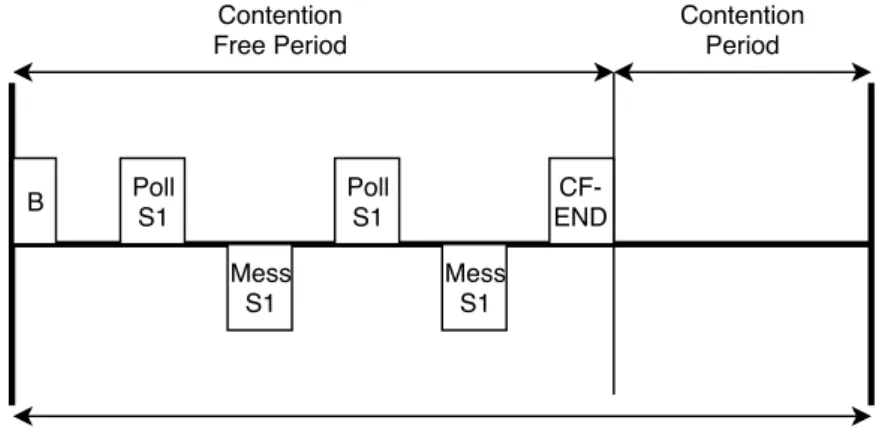
The IEEE 802.11 standard also includes Point Coordination Function (PCF) and Hybrid Coor-dination Function (HCF) [7]. PCF is considered obsolete in the current version of 802.11 and HCF is intended to be the replacement for PCF. Both of these methods can provide selection of stations with exclusive access to the medium at set intervals which can enhance performance for applications demanding data at set intervals. The coordination is done with a centralized AP sending poll requests to selected stations within a set contention free period. After the period has ended the stations are free to operate using the regular DCF until a beacon is sent out from the AP signaling the start of the next contention free period. In HCF the ability for the AP to poll stations outside of the CFP is added. When a polling frame is detected control over the medium is given to the AP until its released and normal communication can continue. Figure 2 shows how
the communication cycle for PCF works. HCF works similarly but with the added ability to poll during the contention period.
Poll S1 Mess S1 Poll S1 Mess S1 Contention Free Period Contention Period B CF- END Communication Cycle
Figure 2: Simplified view of the communication cycle for PCF. Each contention free period is started with a beacon message (B) and ends with a CF-END message.
Below is an evaluation of the real-time properties of the 802.11 protocol. The protocol can be used for both time-triggered and event-triggered traffic with the use of a centralized AP running in HCF or PCF configuration. This has the drawback of when the AP goes down the whole system stops functioning which decreases reliability of the solution. The protocol doesn’t define any interference resistance mechanism, instead the CSMA/CA mechanism for medium sensing and re-transmission is used to ensure that the packet reaches its destination.
• MAC: CSMA, Polling.
• Max access: Yes, if PCF or HCF is used. • Frequency: Commonly 2.4GHz or 5GHz.
• Flexibility: Good, new stations can be added easily outside of CFP. • Bandwidth: Depends on the version. Up to 1Gbps.
• Time-triggered support: Yes, with PCF and DCF. • Event-triggered support: Yes.
• Reliability enhancing: No, relies on Re-transmission. 2.3.2 Cellular communication
With the development of data communications and telecommunications the cellular network was born [6, p. 429-451]. The technology is the basis for the current 3G and 4G networks and all of its predecessors. An area selected for coverage is divided into smaller areas called cells, each with its own set frequency band. Connected devices can seamlessly drift between cells as the device is moving out of range of a cellular transmitter and into the range of another through a process called handoff. To connect a device to the network a Subscriber Identity Module is needed, also known as a SIM-card. The card holds information specific to a carrier such as encryption keys, which networks the card is allowed to access and a unique identification number. With cellular communication the user have no control over the network, everything is controlled by the carrier whom owns the network.
The 3rd generation of cellular communication was introduced to support higher data rates capable of video streaming [6, p. 457-465]. Two technologies were developed, Universal Mobile Telecom-munications system (UMTS) as the European standard and CDMA200 as its American equivalent.
The main technology behind the third generation is the Code Division Multiple Access (CDMA) scheme which encodes each stations messages with a code to provide multiple station access to the medium. With CDMA it is possible to offer a graceful degradation of the network as the number of stations increases with network speeds between 384 kbps - 3 Mbps in the original standard depending on network load and signal intensity.
With the fourth generation the network is switched over to be fully IP-packet based [6, p. 470-507]. Long-Term Evolution(LTE) was the winning design to be implemented as the forth generation. With the solutions being designed to maximize bandwidth and a signals spectral efficiency, it is possible to get network speeds up to 100 Mbps for mobile-access. Different access schemes are employed for the up-link and down-link. Single-Carrier Orthogonal Frequency Division Multiple Access (SC-OFDMA) chosen for the up-link for its energy saving characteristics, and pure OFDM on the down-link for increased bandwidth. LTE supports the use of Quality of Service (QoS) to provide different priorities to different packets. With QoS it is possible to decrease the packet delay and the packet error loss rate.
At the time of writing the fifth generation of cellular networks are in the final stages of design [9]. With an increase in speed up to 1 Gbps and latency reduced from 20ms round trip to 1ms, a 5G network is looking to incorporate a range of network solutions with seamless connectivity between the networks. With the explosion of connected devices, 5G is looking to become a viable communication solution for embedded systems.
• MAC: CDMA(3G), SC-OFDMA/OFDMA(4G). • Max access: Yes.
• Frequency: Depends on the carrier.
• Flexibility: Good, just add a SIM-card to the new device. • Bandwidth: Up to 3 Mbps(3G), 100 Mbps(4G).
• Time-triggered support: Yes. • Event-triggered support: Yes.
• Reliability enhancing: Included in CDMA and OFDMA. 2.3.3 IEEE 802.15.1
IEEE 802.15.1 also known as Bluetooth, is a short range wireless solution developed by Ericsson in 1994 [6]. The goal of Bluetooth was to make communication between devices easier by replacing the cables that connect them. It is a low power and low cost solution on a microchip and is now used in a wide variety of electronic equipment, such as handsfree headsets, computers, medical equipment and many more. Using the 2.4 GHz unlicensed band makes it easy to use anywhere in the world without worrying about using frequencies that are illegal.
There are different version of Bluetooth such as Basic Rate (BR), Low Energy (LE) and high speed Enhanced Data Rate (EDR) [6]. These versions differ in power usage, range and data rates. While the range for the basic rate is only around 10 meters, the low energy version can achieve up to 150 meters as long as the devices are in line of sight. Meanwhile the data rates go from around 1 up to 24 Mbps depending on which version is being used. Communication is controlled by a master node to which up to 7 slaves can be connected over the same physical channel, and together they form a piconet. A node in a piconet can serve both as a master in one network and slave in another creating a larger scatternet. However a master/slave station that is the link between piconets in a scatternet is not always able to route between the piconets [10]. This is due to the core specification of Bluetooth is lacking routing capabilities which have to be added by a higher level protocol. Figure 3 shows a basic Bluetooth scatternet topology. Unlike BR and EDR operation the nodes in the LE variant do not share the same physical channel. The master node
has instead a separate physical channel to each of its slaves. Scatternet M S S S/M S S Piconet A Piconet B
Figure 3: Bluetooth topology.
For communication the physical channel is divided into 79 channels of 1 MHz each [10]. An adaptive frequency hopping (FHSS) scheme is employed for interference resistance based on the master nodes clock and a network address. This gives the protocol better usability in presence of other non-hopping networks in the unlicensed 2.4 GHz band. Access to the medium is given in time slots (Time Division Duplex) during which a transaction of a packet can occur either broadcasted or unicasted. A packet in not constrained to a single time slot and can take three or five if large enough. After each transaction the frequency hop occurs before the next packet can be sent and received. Time slots can also be reserved for synchronous data transfers like voice data. Figure 4 shows basic Bluetooth operation in piconet with 2 slaves.
TX Master Slave 1 Slave 2 Slot n TX
Slot n+1 Slot n+2 Slot n+3
TX
Slot n+4
Figure 4: Basic Bluetooth communication.
Bluetooth supports both event-triggered and time-triggered types of communication with the two modes of packet transfer. It is resistant to interference by other networks on the same frequency spectrum due to the implementation of FHSS.
• MAC: TDD-TDMA.
• Max access: Yes, in synchronous mode. • Frequency: 2.4GHz.
• Flexibility: Up to 8 devices per piconet. Piconets can be connected to form a scatternet. • Bandwidth: Up to 24Mbps.
• Time-triggered support: Yes, in synchronous mode. • Event-triggered support: Yes, in asynchronous mode. • Reliability enhancing: FHSS.
2.3.4 IEEE 802.15.4
IEEE 802.15.4 [11] details a standard for low-rate, low-power, wireless network communication. The protocol can support either a star topology with central coordinator dictation communication or a peer-to-peer mode were every device can talk to each other as long as they are in the range. The standard includes both physical aspects of how the data is sent, as well as how control of the medium is given. The rest of the implementation is up to a user. Medium access control can be done by superframes which are sent from the coordinator as beacons messages, or without beacon messages relying fully on CSMA/CA instead. In a beacon enabled network each superframe is divided into an active and a inactive periods with the inactive part being optional. During the active part communication can occur, and during the inactive part the coordinator is able to enter a low-power mode saving power. Each active period is divided into a Contention Access Period (CAP) and a Contention Free Period (CFP). During the CAP access is granted in slotted ALOHA or CSMA/CA with a station competing for access. This period is also used for new devices wishing to join the network. In the CFP guaranteed access can be given to nodes removing the need for ALOHA and CSMA/CA. Each CFP is divided into seven slots, where a transaction is allowed to take up to several slots. A sending device must complete the transaction before the end of the CFP. Figure 5 shows the communication cycle for 802.15.4 on a beacon enabled network. Since the protocol only encapsulates the physical and part of the data-link layer many different imple-mentation standards based on IEEE 802.15.4 have emerged.
Communication cycle
Beacon Beacon
CAP CFP Inactive
Figure 5: 802.15.4 Communication cycle on a beacon enabled network. A. ZigBee
ZigBee3 was released in 2003 by the ZigBee Alliance and is based on the IEEE 802.15.4 protocol. ZigBee is meant to be a low-cost and low-power consumption wireless solution. The frequencies used for ZigBee are unlicensed bands: 868 MHz for Europe, 915 MHz for USA and Australia and 2.4 GHz worldwide [6]. The data rate that can be achieved depends on which frequency is being used. The 868 MHz band has a data rate of around 20 kbps, while 2.4 GHz band has data rates up to 250 kbps.
There are three different ZigBee devices that has their own role in a ZigBee network: ZigBee coor-dinator, ZigBee router and ZigBee end-device [6]. The role of a ZigBee coordinator is to maintain
the network and supply other devices with keys to keep the network secure. ZigBee routers are used in networks that use tree or mesh topologies and their role is to forward traffic to other devices. ZigBee end-devices communicates with either a ZigBee coordinator or a ZigBee router, and they are not able to forward traffic to other devices. To keep power consumption low, ZigBee can take advantage of beacon-based networks. This means that beacons will be periodically sent out to the devices to wake them up to send data and then go back to sleep. This solution makes it possible for the devices to sleep most of the time which in the end keeps power consumption low. B. ISA100.11a
Designed and developed by the International Society of Automation (ISA), ISA100.11a is intended to be used in process automation together with other protocols under ISA100 [12]. Based on IEEE 802.15.4 with IPv6 and UDP on top the protocol, it provides a flexible platform for applications. The unique data-link layer implements time slotting and frequency hopping adding resistance to-wards interference and allows multiple devices access to the medium. Mesh, Star and a mix of the two are the supported network topologies with a limit to how many hops are supported. Security is also a part of the protocol allowing encryption and integrity check of the data to make sure no tampering has been done in transit. The ISM 2.4 Ghz band is used for this protocol together with Direct Sequence Spread Spectrum (DSSS) making the protocol usable even if other networks are present in the same frequency band.
C. WirelessHART
Based on IEEE 802.15.4 just like the ISA100.11a protocol these two have much in common [12]. Developed from the HART communication protocol for wired communication and designed as a communication solution between sensor/actuator nodes and control equipment. Unlike ISA100.11a the MAC from IEEE 802.15.4 remains unmodified and retains the standard data-link layer. Time slotted communication with frequency hopping is also used in this protocol to provide multiple stations access to the medium as well as interference resistance. Star and mesh topologies are supported with no restrictions on amount of hops. Using the 2,4 Ghz ISM frequency band with DSSS the protocol is usable worldwide.
D. WIA-PA
Developed by the Chinese Industrial Wireless Alliance for process automation based on the IEEE 802.15.4 standard the protocol was accepted as a standard in 2008 [13]. Supporting a star-mesh network topology where the field devices, such as sensors or actuators act as star spokes. The center of the star contains the mesh-network which handles the routing. Both the 868/915Mhz and 2,4 GHz frequency bands are supported providing a user with choice of frequencies. Using the 802.15.4 superframe instead of the time slotted approach sets this protocol apart from its contem-poraries.
To summarize, most 802.15.4 implementation utilize CSMA/CA or TDMA for MAC. ALOHA is also an option if needed. The medium access time is predictable in most implementations. In the basic 802.15.4 superframe beacons needs to be enabled for scheduling to work. Most implementa-tion have some sort of interference resistance reducing the need for re-transmissions either DSSS or frequency hopping or both.
• MAC: CSMA/CA, TDMA, ALOHA.
• Max access: Yes, in a beacon enabled network. • Frequency: Depends on implementation.
• Flexibility: Good, new stations can join and leave easily. • Bandwidth: Up to 250kbps.
• Time-triggered support: Yes (In beacon-enabled networks). • Event-triggered support: Yes.
3.
Related Work
Many studies have been done that are comparing or improving different wireless solutions for real-time communication. In [14] comparisons have been made between 802.11b, Bluetooth and Zigbee from the technical specifications and features for industrial applications. The evaluation was done as a literateur study with the main comparison criteria being Power profile, Complexity, Latency, Range, Extendability and Data rate. After the main comparison a deeper comparison was done between Zigbee and Bluetooth with the conclusion being that Zigbee fits the requirements for industrial applications better. A more in-depth comparisons with real-time communication in mind have been made in [15],[16]. Both present an overview of most of the wireless protocols that exist, their strengths and weaknesses. Specifically in [15] the paper present a comprehensive study of the most commonly used wireless protocols. It is concluded that since many of the protocols operate in the 2.4 GHz ISM band, resistance against interference from other competing networks becomes valuable. In addition, most protocols implementing frequency hopping features can be-come unstable if not enough bandwidth is present in the frequency band. In [16] simulations have been made in addition to a literature study to test how human made traffic differs from machine made traffic and what impact the different types of traffic have in real-time systems by looking at sending probabilities. Several different MAC are tested with the conclusion that a version of CDMA might be a good fit for networks with mixed machine and human traffic.
Other works focus on single protocols, e.g., whether Bluetooth low-energy (BLE) radios can be exploited and have a custom protocol built on top of the existing radio solution [17]. Experiments with the custom protocol approach show how it’s possible to guarantee time-slots with devices connected through BLE, such as phones. The paper [18] provides a mathematical model for the performance of the IEEE 802.15.4 protocol in the beacon-enabled mode. The model can be used for evaluation of the 802.15.4 protocol in beacon-enabled networks, where it is used to derive the probability of successfully transmitted packets given different topologies and loads. The resulting model is validated through simulations. In [19] different the different MAC in the IEEE 802.11 protocol are compared. The results demonstrates the limitations of the different access mechanisms has while handling real-time traffic in environments where multiple stations operate in the same frequency channel.
This thesis similarly compares properties and functions of different wireless solutions as prepara-tory work and then builds upon it by implementing chosen protocols in a real lab environment. This is done to get numerical data to compare instead of just doing a theoretical comparison. Sim-ulations could have been run but since the goal is to produce a lab assignment on real hardware this approach is chosen instead of a simulation.
Sj¨ostr¨om and Andersson present in their work [4] three different design proposals for a lab as-signment in embedded systems. They proposed using a modified 802.11 either with software TDMA implemented on top of the 802.11 stack or modify the MAC layer of the 802.11 protocol. Another proposal was to get dedicated hardware for Bluetooth, 802.11 and Zigbee to test the different MAC-schemes presented by the protocols. In the end none of the above solutions were implemented either due to the technical knowledge needed or budget constraints. Instead event-triggered, time-triggered and a hybrid between the two communication solutions were implemented on unmodified 802.11 as the lab assignment.
Our work as well as the work of Sj¨ost¨orm and Anderssons, have the goal of designing a lab assignment for courses in communication for embedded systems. What differs between the works is that whilst theirs focuses on the software side of communication design ours focuses on the hardware and protocols. Both have conducted experiments to get numerical data for comparison between different software designs of communication. Ours included a comparison between protocols as well as the different software designs.
4.
Method
To answer the research questions the methods used in this thesis include literature studies and testing on a lab platform with numeric evaluation. The work started with literature studies to find out more about embedded systems and different wireless communications solutions and which one(s) would be suitable to use in a lab assignment for embedded systems. Further research in-vestigated different types of hardware that can support the selected protocols. At the same time the research questions were clarified based on the literature study. The next task was to figure out how the lab assignment can be designed and what requirements it may have. With the require-ments in place, wireless protocols and the hardware for the alignment of implementation chosen it was implemented on the hardware. With the implementation done it was tested and assessed. If the results proved inconclusive the process could be rolled back to an earlier stage for refinement. Figure 6 shows the steps of the research process.
Literature study Research and choose hardware Clarification of research questions Design lab assignment Set requirements
Implement the design
Evaluate the design
Draw conclusions based on the result
5.
Design and implementation of the lab assignment
This chapter goes through the different hardware choices that are available when it comes to designing the lab assignment. Further down it is explained which choices were made and why they were considered the most appropriate to use for the lab assignment. Finally the setup and implementation are described.
5.1
Hardware
There are a lot of different hardware platforms designed for rapid prototyping and development, all with different strengths and weaknesses that could be used to emulate an embedded system. To help with narrowing down the choices a list was compiled with the features listed in order of importance:
1. Support for RF-modules for Zigbee, Wi-Fi and Bluetooth. 2. Support for a real-time clock.
3. Support for a RTOS.
4. Having good documentation.
Using this list in conjunction with budget constraints the amount of choices was lowered down to three different platforms manufacturers: Raspberry Pi (RPi), Arduino and Texas instruments (TI). From this point on we looked at which manufacturers platforms have better real-time prop-erties, such as a real-time clock (RTC) and RTOS as well as what wireless solutions they have available and how these are implemented. Another important part is to have a platform that is well documented so that help about problems that might appear can be found when needed. To compare documentation we looked at both the official documentation and searches about the hardware outside of the official website. Having information from multiple sources can make it easier to handle a problem in case it occurs. From each manufacturer we chose one platform which best fits our criteria.
5.1.1 Raspberry Pi
From RPi we chose the Raspberry Pi 3 Model B+4. It supports both Bluetooth and Wi-Fi from out of the box only a Zigbee module would be required to fully support all of the chosen protocols. However, the real-time properties of the system are lacking. It is missing a real-time clock which would have to be added as an external module and using Rasbian5 as the main operating system [20]. Rasbian, based on the Debian distribution of Linux is missing most of the features defining a RTOS and comes with a lot of overhead. The RPi 3 Model B+ allows for a custom operating system to be put in place of the original and using a RTOS instead solves the issue of the kernel not supporting real-time. The problem with switching operating system is that drivers support of the already built-in network interfaces is not guaranteed and in the worst case will not function at all. This could be solved with replacing the non-functioning interfaces with modules after initial testing but this adds cost and increases uncertainty. Documentation for the RPi is very good, both the official documentation and the hundreds of projects all using the RPi as the main platform. 5.1.2 Arduino
Arduino has many different platforms to chose from, most of which are missing built-in RF-modules. The Genuino Zero 6 was chosen to represent Arduino due to the built in RTC and increased processing power and memory over the baseline Uno 7. Networking will have to be added as modules and for easy swap-ability of modules a wireless shield8 can be slotted into the
4https://www.raspberrypi.org/products/raspberry-pi-3-model-b-plus/ 5https://www.raspbian.org/
6https://store.arduino.cc/genuino-zero 7https://store.arduino.cc/arduino-uno-rev3
Zero. The Arduino is shipped without an operation system. The user instead writes the code directly to the firmware of the device. For RT-capability either custom code can be written to allow for most of the features of a RTOS or one of many existing RTOS:es ported to the device can be used. Documentation for the base platform is plentiful, if a RTOS is used the documentation depends on the availability of documentation for the operating system.
5.1.3 Texas Instruments
Representing TI will be the dev-kit SimpleLink CC2652R9. The dev-kit have a built-in RTC and support for both Zigbee and Bluetooth out of the box, Wi-Fi would have to be added as a module. The platform comes with the TI-RTOS10containing a protocol stack and drivers and support for RT. Official documentation is easy to find and plentiful but documentation outside of the Texas Instrument website is non existing.
5.1.4 Selection of platform
Below in Table 2 the properties of the platforms discussed in the previous sub-chapters are sum-marized for readability.
Table 2: Comparison of platforms.
RPi 3 Model B+ Arduino Zero TI CC2652R
RTC Yes (module) Yes (built-in) Yes (built-in)
RTOS No (Can be added) No (Can be added) Yes
WiFi Yes (built-in) Yes (module) Yes (module)
Bluetooth Yes (built-in) Yes (module) Yes (built-in)
ZigBee Yes (module) Yes (module) Yes (built-in)
Documentation Good Good Poorer
The platform we chose to base this assignment on is the Arduino Zero, the reasoning for this is simply that Arduino has everything that we need to work with. It also has a big user base which makes it easy to find documentation and help if something goes wrong. Having all of the networking done by modules makes it easy to swap communication solution. One program can be written and it will work with all of the modules without modification. Writing code directly to the firmware is also a bonus. For a simple program that only needs to do one task a RTOS might not be necessary since there are no tasks competing for proccessing time. While the RPi 3 Model B+ could work well, it is closer to a computer system rather than an embedded system. The lack of Zigbee and a RTC also adds complexity since now the function of the modules needs to be taken in consideration. The TI CC2652R on the other hand is close to Arduino Zero but the lack of documentation from outside sources could make it hard to work with. Having one of the selected protocols missing adds the same shortcoming as RPi.
5.2
RTOS
Since the Arduino Zero is shipped without any operating system, multitasking and preemption for high priority tasks is not possible. To add support for the features, a RTOS is needed. The OS will have to be light-weight due to the low amount of memory available on Arduino Zero. It also needs to be easy to use and support common programming languages. In our search we found several candidates as the RTOS of choice for this work.
RIOT OS
RIOT OS11is an open source operating system built on Linux for Internet of Things devices. The OS is light weight with real-time capabilities and multi-threading support. Arduino Zero is sup-ported out of the box and the RTOS also supports most of the common programming languages.
9http://www.ti.com/tool/launchxl-cc26x2r1 10http://processors.wiki.ti.com/index.php/TI-RTOS 11https://riot-os.org/
To flash the OS and sketches at Arduino, a Linux machine with a cross compiler is needed, which adds unnecessary steps.
FreeRTOS
FreeRTOS 12 just like RIOT OS, is an open source light-weight OS with real-time and multi-tasking. The RTOS is ported to Arduino Zero and integrates into the Arduino IDE as an addon library. No special requirements are needed like the cross-compiler for RIOT OS.
Since one of our requirements for the RTOS was to be easy to use, we decided to go with FreeRTOS as the RTOS of choice. It enabled us to use the existing Arduino IDE without needing a Linux VM/computer for compiling purposes. When compiling the library files we encountered a compiling error for SysTickHandler. To solve this we modified the port.c file13 to instead use the existing systickhandler of Arduino Zero.
5.3
Testing setup
To test the hardware a simple distributed temperature sensor design was implemented. Two nodes were used with one acting as a sensor node and the other as the controller. The temperature sensor is connected to the sensor node which will have the task of reading the temperature and sending the data to the controller which will then act upon the information by controlling LED:s. Below is a list of the components that were used to set up both of the nodes.
• 2x Arduino Zero • 2x Breadboard
• 2x Arduino Wireless shields • 2x USB to Micro-USB Cables • 2x Digi Xbee S6B
• 2x Digi Xbee S2C
• 2x Seeed Studio BLE(dual mode)Bee • Jumper wires
• DS1820+ Digital thermometer • Led Lights
5.3.1 Controller node
Since the controller node will be acting on the data sent by the sensor node, this node will have the LED:s connected to it. The positive sides of the three LED:s were connected to the Digital PWM pins 8, 12 and 13 while the negative side were pooled together and connected to a ground pin. Between the positive connections of the LED and the Arduino a 330 ohm resistor is placed. Figure 7 shows the fully assembled controller node. The three LED:s serve as indicators for different states of the system. The green LED is on when the communication is up and working and no packet loss or delayed packets are detected. If the connection is down or packet loss is detected the LED turns off indicating a connection problem. The yellow LED turns on when the temperature is above a set threshold and if the temperature stays above the threshold for 4 seconds the red LED will turn on as well. Both LED:s are reset back to the off-state when the temperature is below the threshold.
12https://www.freertos.org/
Figure 7: Fully assembled controller node.
5.3.2 Sensor node
The sensor node handles the retrieving of data from the sensor and sends either a control signal or the raw data itself to the controller node. To attach the temperature sensor to Arduino the power pin is connected to the 3.3v output pin, the data pin is connected to the Digital PWM pin 2 and the ground pin to ground. A 4.7k ohm resistor is placed in between the data and power pins to reduce the chance of reading errors. DS1820+ is run at the default settings giving a 12-bit resolution and 750ms polling time. Figure 8 shows the fully assembled sensor node. To read the data from the sensor the one-wire-bus and Dallas temperature libraries are downloaded from the built-in library manager. The one-wire-bus provides the means to communicate with the sensor and Dallas temperature adds an abstraction layer on top providing easy communication with the sensor through function calls.
5.3.3 Communication setup
For the testing three different communication configurations were needed to be setup. Since all of the modules communicat with Arduino over a serial connection only minor changes need to be done to the code itself. For switching between modules the serial speed needed to be changed to match that of the module itself. For setting up the Digi based modules the software XCTU14 was used to access and modify the settings. There is a switch on the wireless shield which redirects the serial connection from the computer to the module instead of the Arduino board but this does not work on Arduino Zero due to its serial setup. For the software to find and recognize the modules a pass-through sketch had to be written to Arduino Zero forwarding all data from serial to serial connection in software. This allows the software to send the required packets to set the module to configuration mode, after which the settings can be changed and saved.
Wi-Fi
To setup the Wi-Fi module the XCTU software was used. The module on the sensor node was configured as a soft-ap meaning the module would operate as an access-point allowing the other module to connect. Setting up the modules in ad-hoc mode was tested but proved hard to get working correctly, therefore the soft-ap mode was used for the testing. After setting the module to serve as an AP the SSID and authentication needs to be configured for the node to start advertising itself. Static IP-addresses were then configured and the destination field was set to the address of the corresponding node.
Zigbee
Just like the Wi-Fi module XCTU was used to setup the module. For the communication to work one of the modules is configured as a coordinator. The PAN IDs of the modules are then set to the same value and both the low and high destination address is set to the corresponding node. Bluetooth
Since the Bluetooth module is not produced by Digi the XCTU software would not work for con-figuration. Instead commands had to be sent over the serial connection to the module to configure it. An Arduino sketch was put together sending the appropriate commands to the module. To get the modules to connect to each the sensor nodes module was set to master. For the programs to be able to send data to the Bluetooth module the speed of the serial connect had to be modified to a baud rate of 115200 instead of the original 9600 as was used with the other modules.
5.3.4 Time synchronization
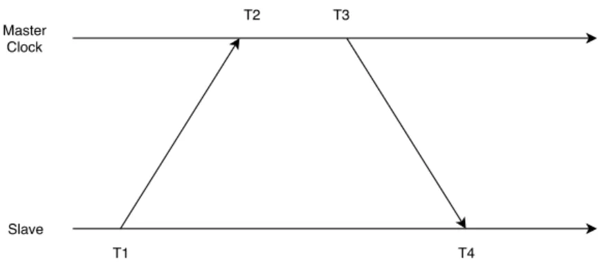
For evaluation purposes both of the nodes need to be within the same time domain. Since none of the devices is connected to an external time server, synchronization needs to be established between the two devices where one serves as the master clock and the other synchronizes to the master clock. To achieve synchronization the offset calculation described in [21] was implemented. Figure 9 shows where the time stamps are taken in relation to time, and Equation 1 describes the algorithm used to calculate the offset.
The original plan was to use the real time clock of Arduino Zero as a hardware time source for time stamping. This plan was quickly discarded when it was discovered that it could be only possible to receive the time in whole seconds. To get time stamps in the micro or milliseconds the time stamps would have to be generated by software which will decrease the accuracy of time synchronization. With this constraint in mind, to get the best possible accuracy the amount of micro seconds passed since the start of the program was used as the basis for the time stamps. In addition the synchronizing node will discard any calculated offset that deviates from the previous with +/- 5 milliseconds. This ensures the offset will not change drastically during testing. This choice however can lead to more inaccuracy if the first calculated offset is really inaccurate since the next more accurate offset will be discarded. Therefore it is imperative to keep logging the
offset during testing for later analysis. T1 T3 T2 T4 Master Clock Slave
Figure 9: Time stamps of the offset calculation.
O = (t2 − t1) − (t3 − t4)
2 (1)
5.3.5 Types of programs
Three different programs are tested: time-triggered, event-triggered and hybrid program. These programs are different in the way the communication is handled and show if there is a specific wireless protocol that is better suitable for a certain type of communication. The time-triggered solutions sends data at set intervals while the event-triggered solution sends when a threshold is reached. The hybrid solution is a mix of the time-triggered and event-triggered approaches sending keep-alive messages at set intervals and event based packets when the threshold is reached. Time-triggered program
This program’s communication is triggered by passing of time. The sensor node reads the data from the sensor and sends it to the controller, which then uses the data to make a decision. After reading and sending the data, the reading thread of the sensor node sleeps for one second. This makes the system to send an updated packet about every 1.5 second. Each packet contains a sequence number for packet loss tracking and the data itself. When the packet is received by the controller node, the data is checked against a threshold and if it exceeds the value the yellow LED turns on. At this time a time stamp is taken and compared against to start the countdown to turn the red LED on if 4 seconds passed without receiving a packet with a temperature value below the threshold. If the controller were to not receive a packet for 5 seconds the green LED turns off indicating a problem with the network.
Event-triggered program
Instead of being based on time, this program’s communication is triggered by an event. The sensor node collects its data from the sensor the same way as in the time-triggered program, and makes a decision to send a control signal to the controller or not. This decision is based on what the temperature reading is and what the last sent packet was. If the last sent packet was the control signal for being above the threshold and the new value is still above the threshold, no packet will be sent. If the new value instead is below the threshold and the previous packet was carrying information about this value being above, a new packet based on the last value is generated and sent. The controller node receives either a 1 for being above the threshold or 0 for being below, and acts accordingly. The LED:s work in the same way as in the time-triggered program with the exception of the network indicator LED. Since packets are sent sporadically the node have no way of knowing if the other node is alive or dead. The only way to see network issues is by looking at the sequence number. Therefore the network indicator LED is not used in the event-triggered program.
Hybrid program
The hybrid program mixes the sporadic control signals of the event-triggered program and sends keep-alive messages at regular intervals to give the controller node an updated state of the sensor node. The keep-alive messages are sent out every 5 second to indicate that the sensor is alive. Here the network indicator is used again and if no packet is received within 12 seconds the controller node turns the green LED off. The control signals works the same as in the event-triggered program were packets are only generated when something new happens, e.g., the temperature reading is below the threshold when it previously was above.
5.3.6 Test environment setup
The testing is done in three different environments to see how well the system works in certain en-vironments. First is the baseline test which is done to get baseline results for comparison purposes. The second test is the interference test, and the last test is the range test. These different tests are needed to evaluate how the system works in different environments. Let’s take the temperature warning system as an example and consider a situation when more sensors were to be added to it. In this case some of them might be placed in different rooms which means the communication range requirement increases and the signals now need to penetrate a wall as well. Another room might be an office with a lot of wireless traffic that could interfere with the system. This makes it important to evaluate how the system works under these conditions. If it doesn’t work, then changes can be made to the application to account for these conditions.
Baseline test
The baseline test setup has both nodes in close proximity to each other and in the direct line of sight. This is to make sure that the signal strength is as good as possible while keeping interference to a minimum. The result of this test will be used to know how much the different protocols suffers from interference and range by comparing it to the other tests.
Range test
The range test is done by having the nodes approximately 15 meters apart and separated by two walls that are made of drywall. This test is meant to represent an office environment where nodes could be separated by several rooms. Light interference is also present in this environment due to the presence of Wi-Fi access-points and people moving around blocking signals randomly.
Interference test
The interference setup is meant to represent a heavy industrial setting where the direct line of sight might be blocked with equipment made of metal and in presence of heavy interference. The nodes are placed in different rooms with a drywall in between. To further inhibit signals, both nodes are covered with a metal pot and a microwave is placed next to the receiver of the controller node. During testing the microwave is run at full power to interfere with the signals. This test checks how well the RF modules can cope in an environment with quite extreme interference and lack of the direct line of sight.
5.4
Testing procedure
The testing was done by first choosing the RF module to run the tests with. The RF modules were then configured and tested to make sure the connection between the modules was working. Once the RF modules were connected, the environment was set up as described in the environment setup, depending on which test was being done, baseline, range or interference. The sketches for the Arduinos were then uploaded through the Arduino IDE and when both nodes were ready they were restarted using the reset button on the Arduinos, making sure the controller was restarted just slightly before the sensor, so no packets would be missing.
The time stamps for delay measurements were taken right before the data is sent over the serial interface to the network module. Since the delay of the serial interface is included the calculated
delay will not represent the actual air time of the packet. With the relatively slow transfer rate of 9600-115200 bits/s depending on the module used the calculated delay will not be representative of the actual propagation time between the modules. Figure 10 shows an illustration of were the time stamps are taken in the communication process.
Arduino Arduino Modem Modem Serial-Link Serial-Link Timestamp Timestamp Mesured Delay
Figure 10: Model of how the delay was measured.
Each test was run until 100 packets had been sent after the first time synchronization. For testing the event-triggred program instead of sending readings from the sensor a random value was gen-erated between a value just above and below the threshold. This was done to reduce the stress of manually warming up the sensor and then cooling it down. The test results were saved using a terminal program such as PuTTy to monitor and log the output of the terminal to a text file for further parsing.
6.
Results
The results and an analysis of the setup are presented in this chapter. Each protocol is discussed in its own sub-chapter and for each type of communication the test results are consolidated into one graph that includes the baseline, range and interference results. Packet loss were tested for during all of the tests but since none were encountered, this data is omitted from the presentation. Due to the different natures of the tested communication schemes the duration of the tests varied from 3 minutes for the time-triggered test to 7-9 minutes for the event-triggered with the hybrid test being in-between. This impacts aspects such as e.g., offsets due to the clock drift over time.
6.1
Wi-Fi
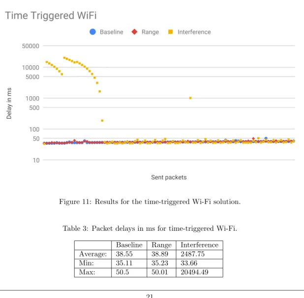
The results for the time-triggered Wi-Fi based solution in Figure 11 show that interference can cause major delays due to the operation of CSMA/CA. When a packet is being delayed due to interference, the buffer on the module will be stacked with packets that are waiting to be sent. This caused each packet after the one that was blocking the serial to have slightly less delay than the one before until the buffer was cleared. This behavior is not optimal, instead the packets should be dropped when the usefulness of the data has reached zero leaving room for a more up-to-date packet to be sent. The high average value in Table 3 for interference is due to these outlier values pushing the average value to 2 seconds. After these large spikes the performance is equal to the other tests. Meanwhile the baseline and range results were performing similar. The minimum, maximum and average values are almost identical. Table 4 show the offsets which stayed the same during the whole run for all of the tests meaning they didn’t influence the large jumps observed for the interference test.
Sent packets Delay in ms 10 50 100 500 1000 5000 10000 50000
Baseline Range Interference
Time Triggered WiFi
Figure 11: Results for the time-triggered Wi-Fi solution.
Table 3: Packet delays in ms for time-triggered Wi-Fi. Baseline Range Interference Average: 38.55 38.89 2487.75
Min: 35.11 35.23 33.66
Table 4: Time synchronization offsets during time-triggered Wi-Fi testing in ms. Baseline Range Interference
Offsets: 1143 5217 19158
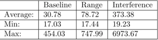
The event-triggered Wi-Fi based solution results again shows how interference affects the CS-MA/CA operation. In Figure 12, both the range and interference tests show huge spikes in delay but unlike the time-triggered results the buffer did not get flooded by new data to send due to the irregular nature of event-triggered communication. Unlike the range test for the time-triggered solution this test show spikes in delay. Since the test environment includes some light and random interference it is likely the spikes are caused by it. Table 5 show an increase in max and average delay for the baseline test over the time-triggered ones. This is most likely due to some background interference caused by other networks in the 2.4GHz spectrum. The large maximum values skews the average for all of the tests but the minimum values looks to be very similar over all of the tests. The minimum values are lower for the event-triggered communication than for the time-triggered communication. This is due to the shorter packet lengths since it does not send the raw data and just a simple control signal reducing the impact of the slow serial connection on the delay results. The offset during the interference test did change unlike the other tests but looking at the result the change in offset did not interfere with it (Table 6). However, the rising values over time can be explained by the inaccuracy of the time synchronization. Over this time the offset should have corrected to the drift but did not. Most likely due to the calculated offsets being outside of the +/- 5ms interval set to throw out unlikely offsets.
Sent packets Delay in ms 10 50 100 500 1000 5000 10000
Baseline Range Interference
Event Triggered WiFi
Figure 12: Results for the event-triggered Wi-Fi based solution.
Table 5: Packet delays in ms for event-triggered Wi-Fi. Baseline Range Interference Average: 30.78 78.72 373.38
Min: 17.03 17.44 19.23
Table 6: Time synchronization offsets during event-triggered Wi-Fi testing in ms. Baseline Range Interference
Average: 1054 4460 14524
Min: - - 14522
Max: - - 14526
The hybrid Wi-Fi results (Figure 13) show increased delays with both interference and range. Compared to both the time-triggered and event-triggered the amount of spikes is significantly lower which might be due to luck of not hitting any interference at the time of sending. Table 7 show that range and interference has similar delays in all of the categories while the average and maximum are higher than for the baseline. Meanwhile the baseline test showed stable delays throughout the test. Just like with the event-triggered results the minimum for all of the tests are lower than for the time-triggered test due to all communication being in control signals. Table 8 shows small changes in the offsets for each test which can be seen by the small jumps of the lines in Figure 13. Sent packets Delay in ms 10 50 100 500 1000
Baseline Range Interference
Hybrid WiFi
Figure 13: Results for the hybrid Wi-Fi based solution.
Table 7: Packet delays in ms for hybrid Wi-Fi. Baseline Range Interference Average: 23.32 41.73 49.84
Min: 18.73 18.06 15.73
Max: 29.12 984.76 949.51
Table 8: Time synchronization offsets during hybrid Wi-Fi testing in ms. Baseline Range Interference
Average: 1381 2208 19223
Min: 1379 2206 19221
6.2
Bluetooth
The time-triggered Bluetooth results shown in Figure 14 demonstrates that interference is the major cause of high delays even for Bluetooth which has enchantments to reduce the impact of interference. The range results show somewhat stable values of delay with some small spikes while the baseline looks fairly even. All of the tests produce a pattern to the delay of the communication, this might be due to the operation of communication for Bluetooth. The master schedules time slots, and since the packets are fairly large as raw data is sent, several time slots are needed maybe even more than what can be scheduled at once. This might be why we see this pattern forming since Arduino also sends the raw data at set intervals to the module. Table 9 shows a small increase in the max delay for the range over the baseline test. The interference test had more and higher spikes than the range test reaching a maximum delay of about 1,1 seconds. This affects the average delay, where the interference test has the highest average while the range test has only a slightly higher average than the baseline test. The minimums are lower for all of the test than for the equivalent Wi-Fi test, this is in part due to the serial communication to the module is running at a higher baud rate reducing the impact of the serial connection in the final calculated delay. Overall, the difference between the minimum and maximum for the baseline test is worse than for Wi-Fi meaning worse performance for time-triggered communication. Offsets in Table 10 remained the same throughout each test.
Sent packets Delay in ms 5 10 50 100 500 1000
Baseline Range Interference
Time Triggered Bluetooth
Figure 14: Results for the time-triggered Bluetooth based solution.
Table 9: Packet delays in ms for time-triggered Bluetooth. Baseline Range Interference Average: 33.32 37.21 71.26
Min: 12.6 9.45 17.42