School of Innovation, Design and Engineering
Master Thesis in Intelligent Embedded Systems
30 credits, Advanced level
Resource based analysis of
Ethernet communication between
software partitions
2
Abstract
Nowadays, Industrial Control Systems (ICSs) are becoming larger and implement more complex functions. Therefore, technologies that are currently used to implement these functions, like hardware platforms and communication protocols might soon become unusable due to the lack of resources. The industry is trying to adopt new technologies that will allow these functionalities to be developed without an increase in the size of the equipment, or of the development costs. To enumerate some of these technologies: virtualization, multi-core technologies are the ones that show the biggest potential. Because these technologies are not mature, research has to be done in order to fully maximize their potential. Another technology that is highly used by the industry is the Ethernet communication protocol. It presents some advantages, but due to the non-real-time nature of the applications that it was designed for, it has to be extended in order to be used in real-time applications. The objective of this thesis work is to model an Ethernet network comprised of software partitions so that it can provide timing guarantees for the traffic that traverses the network. A Response Time Analysis for real-time flows over such networks is proposed. The model and the RTA are evaluated by experiments.
Date: 13 June 2014
Company: ABB Corporate Research, Västerås
Advisor at ABB Corporate Research: Kristian Sandström
Advisor at Mälardalen University: Meng Liu
3
Preface
I would like to start by thanking to my company supervisor, Kristian Sandström for giving me the opportunity of working on this interesting thesis project. Also, I would like to thank him for his invaluable guidance that he offered me throughout the entire period of the project.
I would also like to thank to my examiner Moris Behnam and my supervisor Meng Liu, from the University for their great support and guidance that they have provided me during the development of the thesis project.
I am grateful to Aneta Vulgarakis from ABB Corporate Research for helping me with
invaluable advices in the development of the thesis report and for taking the time to read it and provide very useful feedback.
I am also extremely grateful to my colleagues, Aseem Rastogi and Rizwin Shooja for their help, that they provided me in technical matters.
Last but not least I would like to express my thankfulness to my parents, my brother and my friends for their moral support.
4
Nomenclature
Abbreviations
ICS
Industrial Control Systems
VMM
Virtual Machine Manager
CoTS
Commercial Off-The-Shelf
CBSE
Component Based Software Engineering
VM
Virtual Machine
VIF
Virtual interface (Virtual network interface)
QoS
Quality of Service
NIC
Network Interface Card
ABS
Anti-lock Braking System
RTA
Response Time Analysis
AFDX
Avionics Full-Duplex Switched Ethernet
RAM
Random Access Memory
VLAN
Virtual Local Area Network
HTB
Hierarchical Token Bucket
HFSC
Hierarchical Fair Service Curve
WCET
Worst Case Execution Time
WCRT
Worst Case Response Time
BCET
Best Case Execution Time
HVM
Hardware Virtualized Machine
PV
Paravirtualized
PV-HVM
Paravirtualized over HVM
API
Application Programming Interface
VCPU
Virtual Central Processing Unit
PCPU
Physical Central Processing Unit
OvS
OpenvSwitch
ToS
Type of Service
TBF
Token Bucket Filter
WRR
Weighted Round Robin
DRR
Deficit Round Robin
5
FIFO
First-In-First-Out
MAC
Media Access Control
UDP
User Datagram Protocol
DSCP
Differentiated Service Code Point
6
Contents
Chapter 1 ...8 1.1 Introduction ...8 1.2 Problem formulation ... 10 1.3 Related work ... 13 1.3.1. Virtualization ... 13 1.3.2 Multicore ... 13 1.3.3. Communication ... 14 1.4 Contributions ... 15 Chapter 2 ... 16 2.1 Theoretical background ... 16 2.1.1 Virtualization ... 16 2.1.2 Real-time systems... 172.1.3 Response time analysis ... 17
2.2 Technological background ... 18
2.2.1 Xen Hypervisor ... 18
2.2.2 Real-Time-Xen 2.0 ... 19
2.2.3 OpenvSwitch ... 21
Chapter 3 ... 23
3.1 Software switch configuration mechanisms ... 23
3.2 Configuration mechanisms of the hardware switch: ... 26
3.3 Model of the network... 27
3.4 Model of the software partitions ... 29
3.5 Model of the software switch ... 30
3.6 Model of the hardware switch ... 31
Chapter 4 ... 33
4.1 Analysis overview ... 33
4.2 Analysis method for real-time flows ... 35
4.3 Analysis method for non-real-time and untrusted type of flows ... 38
Chapter 5 ... 41
5.1 Evaluation of the RT-Xen ... 41
5.2.1 Evaluation of the model of the network ... 42
7
5.3 Evaluation of the Response Time Analysis ... 53
Chapter 6 ... 58
6.1 Results ... 58
6.2 Future work ... 59
Chapter 7 ... 60
8
Chapter 1
INTRODUCTION
1.1 Introduction
Industrial Control Systems (ICSs) are a type of control systems used in industrial production, supervisory, data acquisition systems, distributed control systems and other smaller control systems [1]. They are becoming bigger and bigger because of the new functions that they implement, functions that would normally require extra hardware to be added. This would result in increased size, increased number of wires and more expensive ICSs. To overcome these problems, the industry is adopting new technologies like multi-core technology, virtualization [2] technology and different communication protocols. Because of the increased number of functions that they implement, ICSs also need faster and more robust communication protocols to inter-connect all of its sub-systems. This can save companies money during development and also allows them to extend the functions of their systems, without needing to increase the size of the ICSs.
In computing domain, virtualization refers to the virtual version of something, like a virtual computer hardware platform, an operating system, storage devices or computer network resources [2]. One type of virtualization is the hardware virtualization or platform virtualization. It refers to creating a virtual computer also known as virtual machine or software partition, which has the same behavior as a physical computer. It runs an operating system and multiple user applications. An important aspect of virtualization is that, the software that is running in the virtual machine is not dependent of the hardware that the software partition is running on. This means that the software partition can run an operating system, different from the one running in the hardware platform that hosts the virtual machine. An example of such a virtualized system is depicted below, in Figure 1. It consists of a host machine, a Xen hypervisor [3] and multiple virtual machines. The host machine represents the hardware platform on which the virtual machines will run. The Xen hypervisor (Virtual Machine Manager) will manage all the virtualized domains. Domain-
0
represents the first domain that is started by the Xen hypervisor. It contains the host operating system, drivers for the hardware and the management tool stack for the hypervisor. Without Domain-0
, the Xen hypervisor is unusable. Domain-Us represent the guest domains in the system, which are unprivileged domains that have no default access to the hardware resources. Each of Domain-Us contains drivers for hardware access, also named frontend drivers to pair up with the backend drivers, which reside in Domain-0
.9 The multi-core technology refers to the multi-core processors, which incorporate in one silicon chip multiple cores that are able to run different applications in parallel at the same time. One of the multi-core processors advantages is the size of the silicon chip, which in some cases can be the same as of a single core processor. Another advantage of this technology is the physical proximity of the cores to their cache memories. This can lead to faster synchronization times between the cache memories, which share the same system bus, than if the cores were situated in different silicon chips.
Although the concepts of virtualization and multi-core show many advantages from which the industrial environment might benefit, they also come with an increased number of challenges. These challenges are because of the real-time applications used in ICS. These applications are time constrained and have to respond before their assigned deadline. The problem with the multi-core technology is that all of the cores share the same main memory and the same system bus. Therefore, only one core can access the main memory or the I/O peripherals at a time. This can be a source of delay if two or more applications, running in separate cores, want to access at the same time the main memory or the peripherals devices. Only one application is allowed to access the main memory or the peripheral devices at a time. All the others are delayed until each of them will be granted access. The challenges that the virtualization technology raises are similar, and they occur due to the sharing of the resources like physical cores and I/O devices.
Another issue of ICSs is that the industrial environment, where they are deployed, is a harsh environment for electric and electronic systems. Sometimes, parts of the ICS are scattered throughout the plant at long distances from each other and need to exchange an amount of information that is constantly growing. Because of this, a necessity for a fast and robust communication to transfer data, which can withstand perturbations, arises. Since these systems are becoming more and more complex, the amount of data exchanged between sub-systems has also increased. Thereby, a communication protocol that can support high bandwidth transmission and be easily scaled in the future is required. A number of fieldbus protocols are used in industrial computer networks. Out of these we can enumerate RAPIEnet, Profibus, CAN and EtherCAT. RAPIEnet (Real-timeAutomation Protocols for Industrial Ethernet) is a fieldbus protocol, which uses Ethernet as the physical communication support. RAPIEnet uses a ring topology and every node need two Ethernet ports. It supports high speed transfer of data from 100 Mbps up to 1 Gbps. A disadvantage of using RAPIEnet is that due to its ring topology and in case of a hardware
Example of a host computer containing four software partitions
Hardware layer (PCPUs, Memory, I/Os, Network interfaces)
Xen Hypervisor (Virtual Machine Manger) Domain-0
Hypervisor management stack,
virtual disk drives for VMs, Hardware drivers, Network drivers, Virtual switch Domain-1 Windows partition Domain-2 Ubuntu partition Domain-3 Ubuntu partition Domain-4 Fedora partition
10 problem with two of the nodes, multiple nodes can fail to send or receive data. Profibus (Process field bus) is a communication protocol used in the industrial environment. The nodes in the Profibus network are connected through a bus type topology. Profibus has a maximum transfer rate of 12 Mbps in a half-duplex transfer mode. The half-duplex transfer mode means that only a single device can send data at a time. CAN (Controller Area Network) bus is a fieldbus used mostly in the automotive industry. Controller Area Network uses a bus topology with a half-duplex transfer mode, same as Profibus. It supports a transfer rate of 1 Mbps which is lower than the one of Profibus. Another fieldbus used in ICSs is EtherCAT (Ethernet for Control Automation Technology). EtherCAT supports multiple topologies like line, tree and star. It also supports high transfer rates. A big disadvantage is that it requires special hardware, as it doesn’t receives messages, but reads them as they pass through the node.
Ethernet communication is the preferred communication in industrial environments nowadays, because it is a robust and fast communication that can serve well the industrial applications. One of the advantages of the Ethernet communication is its high utilization in computer networks. Therefore the hardware is very cheap and highly available as CoTS. Ethernet can support multiple network topologies like: star, point-to-point and bus that gives it advantages over other types of communications that often can only support one. Ethernet can offer high maximum transfer rates, ranging from 3 Mbps to 100 Gbps, but the newer and faster versions of Ethernet are more expensive. Another advantage of Ethernet is that it was designed to be easily scalable. In this context of ICSs, which become bigger, more complex and implement new functionalities, Ethernet has an advantage over other types of communication. A lot of research is undergoing to develop the Ethernet communication in terms of improving transmission rates and finding new and better physical transmission layers. Today there are several industrial communication techniques based on the Ethernet protocol. This is because of the high bandwidth it supports and its capability to withstand the perturbations of the harsh industrial environments. The biggest drawback of the Ethernet is that it was not designed to be used in real-time applications. It requires special mechanisms or special hardware so that it can be used in such applications.
The thesis report is organized like this: Chapter 1 is the introduction, problem formulation and the contributions of the thesis work. Chapter 2 represents the background and will introduce the concepts used in the thesis scope. In Chapter 3 we will present the developed model of the network and in Chapter 4 we propose a Response Time Analysis method to be applied on the model described in the previous chapter. In Chapter 5 we describe the evaluation performed on the testing equipment and in Chapter 6 we present the conclusions and the future work that can be performed.
1.2 Problem formulation
Industrial Control Systems (ICSs) are becoming larger and larger nowadays because of the new functionalities that they implement. The new implemented functionalities result in an increase of software size. The response of the industry to this increase is an evolution towards Component Based Software Engineering (CBSE). In CBSE functionalities are grouped into components, based on relations between them. The idea of CBSE was to increase the reusability of the software which would ease the development, by reducing the time and the costs of the development. Some important work into this field has been done by Ivica and Larsson and presented in [4]. Usually, on such big systems as ICSs, different functionalities are implemented on different hardware platforms. Thereby, due to the new functionalities, additional hardware is required to deploy the software and that would result in extra costs and extra size of the systems.
11 The implementation of the new technologies like virtualization and multi-core platforms might be a solution to this problem, but the technologies are not yet mature and research has to be done in these fields.
The usage of virtualization and multi-core technologies allows implementation of more than a single functionality on a hardware platform. These functionalities can run spatially separated on the same hardware platform. Virtualization permits deployment of software partitions in any node in the system. These software partitions can be deployed on any hardware platform as long as the required resources of the components are provided. To be able to be deployed in a node, a component needs enough resources like: CPU time, memory and network bandwidth. These components will have to exchange data between them and this is why the nodes they are deployed on have to be interconnected.
A number of communication protocols that can be used in industrial environments are available. Switched Ethernet shows some advantages over other available industrial communication protocols. The advantages that Ethernet has over other protocols consist in the number of different topologies it can support. Different topologies allow easy scalability in the future of the systems that implement the protocol. Also, Ethernet allows high transfer rates and its hardware is highly available as CoTS (Commercial off The Shelf). What Ethernet lacks is that it cannot guarantee the integrity and timeliness of the data, which are critical constraints of real-time systems. Even though it was not designed to serve real-real-time applications, different mechanisms can be used to optimize the utilization of the network bandwidth. Using these mechanisms, a certain level of performance is guaranteed.
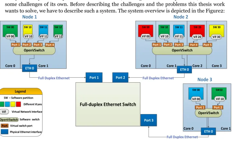
After we have described what are the problems arise in a virtualized environment, we present the system. A system composed of virtualized nodes, running on multi-core platforms, comes with some challenges of its own. Before describing the challenges and the problems this thesis work wants to solve, we have to describe such a system. The system overview is depicted in the Figure2:
Core 0 Core 1 Core 0 Core 1 Core 2 Core 3
Core 0 Core 1
SW 00 SW 10 SW 11 SW 12 SW 00 SW 10 SW 11 SW 20 SW 30
SW 00 SW10
Node 3
Node 1 Node 2
Full-duplex Ethernet Switch
Port 1 Port 2 Port 3 Legend SW – Software partition Different VLans OpenVSwitch
Vif 00 Vif 10 Vif 11 Vif 12 Vif 00 Vif 10 Vif 11 Vif 20 Vif 30
Vif Virtual Network Interface
OpenVSwitchSoftware switch
OpenVSwitch
Port 1 Port 2 Port 3 Port 4 Port 5 Port 1 Port 2 Port 3 Port 4
Port Virtual switch port
ETH 0
Physical Ethernet interface ETH 0
ETH 0 Full Duplex Ethernet
Full Duplex Ethernet Full Duplex Ethernet
OpenVSwitch
Port 1 Port 2
Vif 00 Vif 10
12 The system is composed of several multi-core physical nodes interconnected through a Full Duplex Ethernet communication. Each of the computer nodes runs multiple software partitions. Either several software partitions or just a single one execute on each of the platform cores. In order for all the Virtual Machines to share the physical network connection, the virtual machines are connected to a software switch that allows them to share the physical interface.
After the description of such a system we define the research goals of this thesis:
#Problem 1: Scheduling multiple virtual machines on one physical core of the multi-core
platform and still meet timing requirements of their transmitted frames.
Often, due to the complexity of these systems, multiple virtual machines have to share a single physical core. First of the challenges of these systems is to schedule multiple software partitions on a single core and respect the timing requirements of their transmitted frames. Scheduling multiple software partitions on one physical core means that only one software partition can execute in the core at a time, with the other waiting. The virtual machines execute for some time and then they allow another virtual machine to execute.
Depending on the number of virtual machines that execute in a physical core a significant delay can be introduced for example in the transmission of frames between different software partitions. For example a software partition starts to run an application which sends a frame to another virtual machine. Before it can send the frame on the network another virtual machines preempts the execution of the software partition and start executing in the physical core. By the time the VM has resumed execution and sent the frame, the timing requirement for the frame to reach at destination within a specific time might have been exceeded. We therefore can see a problem in the scheduling of multiple VMs in a physical core. We have to find a solution to be able to predict in which order and for how long does each virtual machine run in a core, to ensure that the data will be delivered before the deadline is exceeded.
#Problem 2: Investigate and use different available mechanisms to configure the software
and the physical switches to reach an acceptable level of QoS (Quality of Service). QoS represents the overall performance level of a network that is normally experienced by its users.
Most of the time the VMs (Virtual Machines) have to share a single NIC (Network Interface Card) in order to send data outside of the physical node. This is done by connecting all the VIF (Virtual Interfaces) of the VMs to a software switch together with the physical interface of the NIC. Therefore, a second challenge is to configure the software switch to reach a certain QoS (Quality of Service) level for the flows in the network. The physical switch, which interconnects all the physical nodes, also has to be configured to improve the network utilization in order to prevent congestion and loss of packets due to overflowed buffers. An investigation of the available mechanisms to configure both switches has to done. Using these mechanisms the network will be modeled to improve its utilization.
#Problem 3: Propose a RTA (Response Time Analysis) for the model of the system
presented in Figure 2, to verify if the real-time constraints of the network flows are met.
A model of the response time analysis for a simple network with one physical switch was developed during a previous thesis work [5]. This thesis work extends the model of the response time analysis for a network of software partitions and takes into consideration the configuration of both switches, hardware and software. For computer networks, different methods are available to upper bound the transmission delay for the flows. Thereby, an investigation on what is the best method for our case has to be conducted. We will apply the selected method to obtain theoretical
13 results for the upper-bounds. Then, we will compare them with the results obtained from the tests performed on the test platform. In all the test cases the theoretical results should be greater than the ones measured on the test platform.
1.3 Related work
1.3.1. Virtualization
Virtualization technology is not yet a mature technology. Thereby, it requires research to be conducted, in order to fully maximize its potential. When it comes to using virtualization technology in real-time applications a series of challenges occur, such as guaranteeing an end-to- end response time of the applications. The most important component of a virtualized environment is the hypervisor. This is the manager of all the guest domains in the system. A number of hypervisors are available, either as open source or as commercial products. Out of these we can mention Xen hypervisor [3], KVM [6] and VMware ESXI [6]. Xen’s main advantage over others hypervisors is that it can offer complete isolation of the execution of the guest domains from the management operating system, the management stack and device drivers. Xen allows scalability of the environment and does not require device drivers. An environment virtualized using VMware on the other hand requires drivers for its devices. KVM uses the Linux kernel as the hypervisor. Xen allows any operating system to be used for the management domain. Xen also allows multiple types of virtualization techniques. In [7] both Xen hypervisor and KVM hypervisor are evaluated. The results show that overall the Xen paravirtualized domain has the lowest RAM (Random Access Memory) memory utilization and lowest CPU utilization out of all guest domains. Xen’s features and performance led to high integration rate into the products by many companies like: Cisco, Citrix, Fujitsu, Lenovo, Samsung and many others [8].
Xen hypervisor was not designed to be used for real-time applications. Therefore, to make it suitable some extensions would need to be created. Work has been done in this field by Sisu et al, which present in [9] a hypervisor scheduling framework named Real-Time Xen. The real-time framework was intended to utilize real-time scheduling theory in cooperation with a highly used Virtual Machine Monitor, Xen. It was supposed to allow the real-time applications to run in virtualized environments. The framework presented in [9], implements different server algorithms and shows that the overhead incurred by complex algorithms is higher than the ones incurred by periodic servers. In this paper they also conclude that the deferrable servers perform well in terms of soft real-time performance. Other work in the field has been done in [10], by Nesredin Mahmud. The author evaluates a distributed multi-core platform by deploying different parts of an orchestra application in different, synchronized, virtual nodes. The author demonstrates that the software partitions are synchronized and that there is potential for deploying real-time applications in a virtualized environment.
1.3.2 Multicore
In the middle of 2000’s the expansion of the transistor technology trend was disrupted. The trend also known as Moore’s law refers to the fact that the number of transistors that can fit in a silicon chip doubles every two years. The trend was disrupted because the heat dissipation on the silicon chip was reached. The multiprocessing has been seen as the only solution to keep the trend of doubling the number of transistors on a chip every two years while still managing the power consumption [11]. The multiprocessing refers to implementing multiple single cores on a single silicon chip. In order to fully take advantage of this technology, as explained by Huard et al. in [11], optimization of writing software has to be done. Code has to be written in a concurrent and well balanced way so that it can be mapped efficiently to the cores of the multicore chip.
14 A number of scheduling algorithms were designed to be used in multicore platforms to improve the computation efficiency of the multicore processors. In [12] Liang-The Lee et al. presented a hybrid task scheduling algorithm for multicore processors in which they apply a two-level hierarchical scheduling to adjust real-time and non-real-time tasks. The results of the experiments show a higher efficiency if the proposed scheme is applied on multi-core architectures than if it wasn’t applied.
1.3.3. Communication
Faster and more robust communications protocols are required given the expansion of the ICSs. One of these protocols is Ethernet and the idea of using it in industrial environments has already been applied and several communication protocols based on the Ethernet communication have been developed. EtherCAT [13], RAPIEnet [14] and AFDX [15] are some examples of communication protocols used in industrial applications. All these protocols come with extensions for real-time systems, as Ethernet was not designed to be used in real-time applications. Thereby, it doesn't provide features like data integrity mechanisms or mechanisms to guarantee the timeliness of the data.
AFDX (Avionics Full Duplex Switched Ethernet) is the protocol that comes to replace older avionics communication protocols like ARINC 429 [16] and ARINC 629 [17]. As time passes by and the avionics systems become more complex, these protocols cannot handle the increasing amount of information flowing through the avionics networks. In airplanes, most of the electronic equipment have hard real-time constraints and this requires end-to end guarantees for the data flows that traverse the network. EtherCAT communication protocol is used for high performance applications, where there is a need for quick response time. Even though it can offer high performance, it requires special hardware, which can be very expensive. It cannot be used for all the components of an ICS, therefore another protocol is required. RAPIEnet is a real-time industrial protocol based on Ethernet. A drawback of this protocol is that it cannot be easy scaled due to its supported topologies. From the point of view of the fault tolerance this protocol can detect the error and recover from a single node failure. All these presented protocols, based on Ethernet, implement extension of the protocol require some sort of extension, most often the hardware support of the Ethernet protocol is modified. Out of all of these presented protocols, some concepts from the AFDX protocol can be used in our case.
To be able to implement any protocol in a system, a method to verify that the constraints for each of the network flows are met has to be used. There are many methods to check if the timing constraints of the network flows have been met. Fraboul et al. mentioned in [18] and [15] several methods which can be used to bound the end-to-end delays for the flows in an AFDX network. One method mentioned by Fraboul et al., is Network Calculus [19] and is used for bounding the end-to-end delays in computer networks, based on the min-plus algebra. The results presented by Fraboul demonstrate that the Switched Ethernet can provide real-time guarantees for its flows and can therefore be used in avionics applications. In [20] Zhen et al. mentioned multiple commercial software products, used for simulation of network communications, like Commet Predicator developed by the CACI company and OPNet developed by the MIL3 company. These tools are used to determine upper bounds for flows in networks. However the drawback of this approach is the limited number of network models provided by the companies that designed the software. The presented model considers two types of traffic, periodic and sporadic. It does not consider that the information that flows through the network has different priorities. The flows in the network should be granted a prioritization in the forwarding, so that the experienced latency is minim for the high priority traffic. Therefore this method cannot be applied to our case.
15 Another method is presented by Diemer et al. in [21], where timing upper bounds are provided per class and not per stream. They presented how a model of Ethernet AVB can be transformed into timing analysis models. They have also shown how the worst-case timing parameters can be computed from those models. However this model is not applicable in our case due to the different network components, such as Ethernet AVB specific switches which have traffic shapers at the egress ports for two of its queues.
Joseph and Pandya have described in [22] a method on how exact response times for tasks can be computed for a system. This method has been extended for many communication applications therefore it can be used in our case.
1.4 Contributions
The main objective of this thesis work is to model different components, based on different available configuration parameters, of a network comprised of software partitions. Based on the research problem defined in second part of chapter one, we identify the following contributions of this thesis work:
#Problem 1: Scheduling multiple virtual machines on one physical core of the multi-core
platform and still meet timing requirements of their transmitted frames.
Installing the RealTime-Xen 2.0 framework on the testing environment and testing different available schedulers, analyze their behaviors and choose the one that performs better in scheduling the VCPUs to be used in the network model. The real-time nature of the applications, deployed in each of the software partitions, requires a predictable behavior of the execution of the software partitions in each core. Sometimes, they share a single core, so the pattern of their execution has to be known.
#Problem 2: Investigate and use different available features to configure the software and
the physical switches to reach an acceptable level of QoS (Quality of Service). QoS represents the overall performance level of a network that can normally, be experienced by its users. Using these parameters, a model of the network will be developed.
The model of Ethernet network comprised of software partitions, through which the flows will be transmitted, has been defined. The network architecture definition was done. Also, the different types of flows that carry data of different priorities have been defined. Using the available QoS configuration parameters of the network components to model the network, flows are prioritized in the network. Some of these parameters include: different queueing disciplines and different priority levels for the traffic. This way the high priority traffic will experience the minimum latency from its source towards its destination.
#Problem 3: Propose a Response Time Analysis (RTA) for the model of the system
presented in Figure 2, to verify if the real-time constraints of the network flows are met.
A method was developed to verify if the assigned real-time constraints of the flows transmitted through the network can be met. The method consists in applying different formulas, based on the priority of the analyzed traffic. The real-time traffic flows have to meet certain temporal constraints. Thereby some of the formulas are applied to see if these constraints are met. Different formulas have been proposed to be applied in the case of the non-real-time traffic, which only have to reach a certain level of performance.
16
Chapter 2
Background
Before we can describe the problem and the work that has been done, we have to introduce some theoretical and practical notions to the readers. First, we will start by explaining theoretical background of the real-time systems and virtualization, Response Time Analysis and afterwards, we proceed by explaining technological background of Xen hypervisor, RT-Xen 2.0 framework and OpenvSwitch.
2.1 Theoretical background
2.1.1 Virtualization
Virtualization refers to the virtual version of something, like a virtual computer hardware platform, an operating system, storage devices or computer network resources. The concept of virtualization in computing dates back in 1960s when it was defined as a method to logically divide the resources of the mainframe computers for different applications. This term is associated nowadays with different computing technologies out of which we can enumerate: storage virtualization (multiple network storage devices which can be perceived as a single one), server virtualization (division of the resources of a physical server into several virtual ones) and network virtualization (sharing network resources by using just a single physical link).
Hardware virtualization is one of the most common types of virtualization and it refers to creating a virtual computer inside a physical computer. The virtual computer behaves similar to the physical one as it also runs an operating system. The virtual computer uses some of the resources of the physical computer, which is called host. The most important resources that are shared by the virtual machines are the CPU, I/O devices, the memory and the storage space. There are different types of hardware virtualization:
Full virtualization
Partial virtualization
Paravirtualization
Full virtualization refers to the simulation of almost all the hardware components of the guest VM in order to allow the specific software to run on it. Partial virtualization refers to simulation of partial of the guest VM environment which in some cases might require modification to the guest programs. Paravirtualization, as opposed to the full hardware and to the partial virtualization types, does not simulate the hardware. Instead, it runs the guest programs in isolated domains as if they were running on a separate system.
A virtualized system is composed of the following:
Hypervisor (Virtual Machine Manager- e.g.: Xen hypervisor)
17 A hypervisor (Virtual Machine Manager) represents a computer software, firmware or hardware, used in virtualized environments, that creates and manages the execution multiple virtual machines (software partitions). The hypervisor layer sits on top of the hardware layer, and is responsible for managing the available hardware resources and distributing them to the guest domains.
A guest domain is a software computer, running on a computer platform and which behaves as a physical computer. The guest domains can run independently, along with other guest domains on the same computer platform. These guest domains can each use a different operating system, without needing to consider the hardware components of the computer platform.
2.1.2 Real-time systems
Real-time computing is defined as the study of the hardware and software systems that are subject to temporal constraints and have to complete their tasks before their assigned deadlines [23]. Real-time systems are computer systems that react to external events, perform computing tasks based on those events and return a response within a period of time. The maximum period of time within which the system or one of its tasks has to return a response is called deadline. Function’s correctness in a real-time system doesn’t only depend on returning a correct response, but also returning it within its assigned deadline. Examples of real-time systems can be found everywhere around us nowadays and to enumerate just a few, Anti-lock Braking System (ABS) of modern cars, airbag deployment system, adaptive cruise control, industrial robots, most of the equipment found in airplanes and so on.
Real-time systems can be divided in two categories: soft real-time systems and hard real-time systems. Soft real-time systems are systems for which the miss of one of its assigned deadlines doesn’t mean the failure of the system although many of these misses can be. To enumerate some of the soft real-time systems: mobile phones, digital cameras, air-conditioning units, fridges. On the other hand, hard real-time systems are systems for which the miss of a single deadline causes the failure of the entire system. Such real-time systems are: airbag deployment units in cars, some airplane equipment, Anti-lock Braking System found in modern vehicles. Sometimes, the functionalities of real-time systems contains both types of deadlines, hard and soft.
Most often, the functions that the ICS (Industrial Control Systems) implement have temporal constrains so they are considered as real-time systems. ICSs contain both hard and soft deadlines for the tasks that they perform.
2.1.3 Response time analysis
To be able to say about a task or a set of tasks which are running in a real-time system that they will meet their assigned deadlines, we have to know what is the maximum time that it will take for the task to complete its job. This computed time, also being referred to WCRT (Worst-Case Response Time) will be the upper bound of our tasks. In the real testing of the system, the measured value should not be bigger than the WCRT. The worst-case response time that can occur for the execution of a task, does not only depend on the time to execute that task. It also depends on the other tasks that are running together with our tasks in the system and that can influence the execution time of our task. In order to upper bound this worst time we have to conduct a Response Time Analysis on our network system and compute the WCRT (Worst-Case Response Time) time for all the tasks that are running in the system.
The WCET of a task, running on a hardware platform represents the maximum amount of time that is required for the task to finish its job, on that specific hardware platform. This WCET
18 can be computed through different methods. These methods as described in [24] by R. Wilhelm et al. and they can be divided into two classes:
Static methods
Measurements-based methods
The static methods do not execute code on the real hardware platform or on a simulator in order to compute the WCET for a task or task set. These methods consist in combining different possible control flows through the task with the abstract model of the hardware platform to compute the WCET.
Measurement-based methods execute the task or the task set on the actual hardware platform or on a simulator, by giving some set of inputs. After the set of inputs is run, only then the WCET and BCET (Best-Case Execution Time) for the given set of inputs can be derived. These types of approximations are not always precise and might not always find all possible solutions and for some complex systems they cannot be applicable to upper bound the WCET.
The Worst-Case Response Time (WCRT) of a task represents the maximum of all the response times of the individual instances of that task. If this specific task instance will finish before its assigned deadline then this means that all the other task instances will also finish before the assigned deadline.
2.2 Technological background
2.2.1 Xen Hypervisor
Xen Hypervisor [3] is a type-1 hypervisor, also known as a “bare-metal” hypervisor, which means that it runs right on the top of the hardware platform. It is developed as an open-source project and it is currently used by Amazon in cloud computing, by Google, Yahoo and many other companies. The hypervisor runs a single host domain and multiple guest domains.
The host domain is known as “Domain-
0
” and guest domains are known as “Domain-Us”. Domain-0
contains the Virtual Machine Manager tool-stack that is used to configure the hypervisor. Also it contains drivers (backend drivers for the network or other, drivers for different I/O devices) and virtual storage disks for the Domain-Us. The Domain-0 is the first domain booted up by Xen. Without it the Xen hypervisor cannot be used. It runs the host operating system through which Xen hypervisor can be configured and has special privileges so that it can access the hardware directly.Guest domains (Domain-Us) are unprivileged domains that have no direct access to the hardware. Each of the guest domain can run a different operating system independent from the host operating system. The Domain-U also runs frontend drivers for different hardware devices it might use. The backend driver runs on the Domain-0 and it receives requests from each frontend driver that wants to access the hardware. It multiplexes the requests and forwards them to the hardware. To run a guest domain a virtual image disk and a network interface are required. The guest domains are configured through the network interface.
Xen hypervisor supports different types of virtualized guest domains:
HVM (Hardware Virtualized Machine) guests – guests for which almost the entire hardware is simulated, that means an entire operating system.
PV (Paravirtualized) guests – guest for which not necessarily all the hardware is simulated and which offer an API that has to be modified.
19
PV-HVM (Paravirtualized on HVM) guests – a mixture of hardware virtualized and paravirtualized guests that offer a better performance than fully virtualized guests through the help of special optimized paravirtualized drivers.
An example of the overview of a Xen virtualized environment is presented in Figure 3:
Figure 3 – Xen virtualized environment
2.2.2 Real-Time-Xen 2.0
RT-Xen represents an open-source virtualization platform designed to provide real-time
guarantees. To the best of our knowledge the RT-Xen is the only framework that comes to extend the Xen hypervisor, so that it can support virtual machines with real-time performance requirements. In RT-Xen 2.0 every domain’s Virtual Central Processing Unit (VCPU) is implemented as either a deferrable or periodic server. A deferrable server is a type of server that has a period p and a budget b. It is released every p time period and it can keep its budget intact, if not used until the end of the period. The periodic server is implemented also with a period and a budget but the main difference is that it cannot conserve its budget until the end of its period and it consumes it as the time passes by. Consider for example a server with a period of 4 ms and a budget of 3 ms like in Figure 4.
Figure 4 – Periodic and deferrable servers
Domain-0
Xen management toolstack
Virtual disk drives for DomUs
Backend drivers for various I/O devices (NIC driver etc.) HVM guest Frontend drivers PV guest Frontend drivers PV-HVM guest Frontend drivers
Xen hypervisor (Xen Virtual Machine Manager)
Hardware platform (contains: PCPUs, memory, I/O devices)
Virtual path D ir ect IO p at h 0 ms 4 ms 8 ms Time[ms] B u d ge t [ms ] Application with execution time of 2ms 0 ms 4 ms 8 ms Time[ms] B u d get [ ms ] Application with execution time of 2ms 2 ms
Periodic server with a period of 4 ms and a budget of 3 ms
5 ms
20 Every 4 ms the server will be replenished with 3 ms credits. If the server is periodic it will consume the budget of 3 ms in the first 3 ms after the budget was replenished. It doesn’t matter if a task is executing or not during the first 3 ms. Considering a task with an execution time of 3 ms arrives at time two after an instance of the server was initiated, then it can execute for 1 ms. Afterwards, it has to suspend its execution. But in the same situation if the server is deferrable, then the task can execute for 3ms because it conserves its budget for the entire period. A deferrable server can be considered as a better solution in some cases, where the budget of the server is smaller than its period.
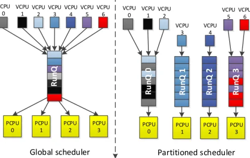
The RT-Xen 2.0 implements two types of scheduling schemes: rtpartition and rtglobal. The rtpartition scheduling scheme, creates a RunQueue for every PCPU (Physical PCPU) in the hardware platform for which it is deployed. For example, if the hardware platform contains four PCPUs, then there will be four RunQueues. Each of the RunQueues will only schedule the VCPUs pinned to its respective PCPU and no other. The rtglobal scheduling scheme consists of only one queue and schedules all the VPCUs of all the VMs on all PCPUs. Therefore, when assigning a new VCPU to be scheduled by the rtglobal, the current utilization of all the PCPUs is considered. Based on it, a PCPU on which the first VCPU in the RunQ will run is computed. We notice that for the rtpartition scheme, we know which other VCPUs are a source of interference for the VCPU under analysis. We know the source of interference because we know which other VCPUs are executed in the same core. For the rtglobal scheme we cannot know what other VCPUs will run in the same core as the VCPU under analysis, because the global scheduler will decide on which core to execute that VCPU.
Both of the scheduling schemes implement two scheduling algorithms to choose what VCPU to run next from the RunQueues: EDF (Earliest Deadline First) and RM (Rate-Monotonic). EDF is a dynamic priority scheduling algorithm that chooses to run next from the RunQueue, the VCPU with the shortest difference between its deadline and the current system time. Rate-Monotonic is a static-priority scheduling algorithm, in which the priorities of the VCPUs are known before start-up time. The VCPU with the shortest period will have a higher priority than a VCPU with a bigger period. Comparing the two scheduling schemes and stating the reasons above, we decided that rtpartion offers a better predictability and can be integrated easier in our analysis. An overview of the two scheduling schemes is presented in Figure 5.
PCPU 0 PCPU 1 PCPU 2 PCPU 3 Global scheduler VCPU 0 VCPU 1 VCPU 2 VCPU 3 VCPU 4 VCPU 5 VCPU 6
Ru
n
Q
PCPU 0 Partitioned scheduler VCPU 0 VCPU 1 VCPU 2 VCPU 3 VCPU 4 VCPU 5 VCPU 6Ru
nQ
0
PCPU 1Ru
n
Q
1
PCPU 2Ru
n
Q
2
PCPU 3Ru
n
Q
3
21
2.2.3 OpenvSwitch
The OpenvSwitch [25] is a virtual switch designed to be utilized in virtualized environments. A virtual switch can be used in virtual environments to connect multiple virtual machines together with the physical interface(s) of the host computer in which the virtual machines reside, in order to communicate with the external environment.
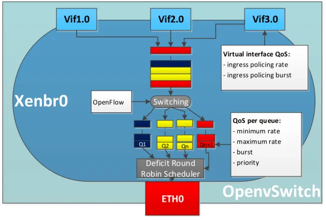
An overview of the internal diagram of a virtualized environment which contains an OpenvSwitch:
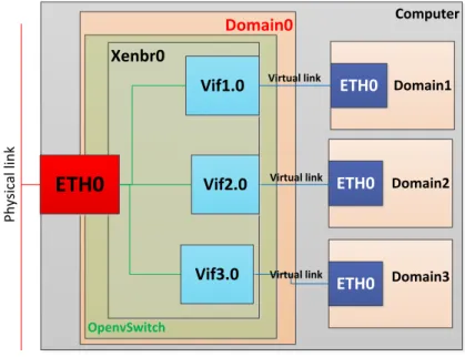
In Figure 6, the OpenvSwitch connects three guest domains with the exterior environment through the help of the “Xenbr
0
” bridge. The OpenvSwitch contains three virtual interfaces for the three guest domains (Vifx.y), where x is the id of the guest domain and y is the instance of the virtual interface on that domain. The interfaces are connected together with the physical Ethernet interface, in order for the domains to share the physical interface. At a moment in time only one virtual machine can send out or receive information on the interface. Since the messages that are sent on the interface are Ethernet frames, they cannot be preempted after their transmission has started. One guest domain can contain if needed more than one virtual interface.OpenvSwitch runs in the Domain-0 which also contains the network backend drivers of the virtual machines. OpenvSwitch is similar to a Linux bridge, but it was designed to be used in more complex scenarios. The OvS (OpenvSitch) has a fast path and a slow path through which frames can be forwarded. The first received frame from a source address towards a destination address has to go through the slow path. Once the first frame was forwarded, any subsequent frames sent on the same path, will take the fast path through the kernel. The kernel path is much faster than through the user space.
The OvS supports forwarding frames just like any other hardware switch and it also supports features like the ones found in advanced physical switches. These features can improve the utilization of the network. We now enumerate and describe some of these advanced functions that will be mentioned later on in the report:
802.1Q VLAN model with VLAN trunks and access ports Computer Domain0 Domain1 Domain2 Domain3 ETH0 ETH0 ETH0 P h ys ic al li n k OpenvSwitch Xenbr0 Vif3.0 Vif2.0 Vif1.0
ETH0
Virtual link Virtual link Virtual link22 It supports the division of network into multiple logical networks that cannot interfere with each other. The division is done by adding the 802.1q tag in the Ethernet frame.
QoS (Quality of service) [26] configuration and policing
The virtual switch allows the configuration of some parameters like: bandwidth of the egress traffic, bandwidth of the ingress traffic, different classes of traffic.
OpenFlow 1.0 plus some extensions
This feature allows users to access the forwarding plane of the virtual switch. The user can create its own forwarding rules that will be introduced in the switch. These rules can be prioritized based on their importance.
Per VM traffic policing
The amount of traffic coming from a virtual machine and going to it can be limited for a better control of the amount of traffic going in the network.
HTB (Hierarchical Token Bucket) and HFSC (Hierarchical Fair Service Curve) queuing disciplines
These queueing disciplines can be used to configure multiple classes of traffic in the network and service this classes with different parameters.
23
Chapter 3
Model of an Ethernet network of software partitions
Before we define the model of the network we have to investigate what were the available mechanisms to model the network, given that we know what hardware and software platforms are used in the network. The core components of the network are the software and hardware switches, as they are the ones that are responsible for carrying all the traffic from one node to another.
3.1 Software switch configuration mechanisms
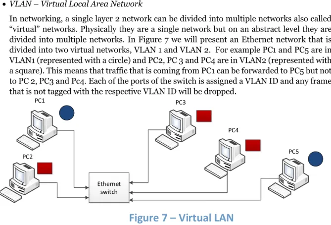
: VLAN – Virtual Local Area Network
In networking, a single layer 2 network can be divided into multiple networks also called “virtual” networks. Physically they are a single network but on an abstract level they are divided into multiple networks. In Figure 7 we will present an Ethernet network that is divided into two virtual networks, VLAN 1 and VLAN 2. For example PC1 and PC5 are in VLAN1 (represented with a circle) and PC2, PC 3 and PC4 are in VLAN2 (represented with a square). This means that traffic that is coming from PC1 can be forwarded to PC5 but not to PC 2, PC3 and Pc4. Each of the ports of the switch is assigned a VLAN ID and any frame that is not tagged with the respective VLAN ID will be dropped.
802.1Q VLAN model with VLAN trunks
The 802.1Q tag is an addition to the 802.3 Ethernet frame standard. It supports prioritizing the Ethernet frames into 8 levels of priorities (0-lowest … 7-highest). Having different types of priority levels in the network allows different types of information like video streaming or voice streaming to be serviced first. These types of traffic are much more important than the retrieval of the information to be displayed by a web page and should be allowed to be sent ahead in the network. Also the tag specifies that in case of congestion in the network, if the frame can be dropped or not. Therefore, unimportant data can be dropped first while important one can be kept. Another information that can be specified in the tag is the VLAN (Virtual Local Area Network) ID. The VLAN trunks allow multiple VLANs to flow through a single network port. Usually a port allows only
Ethernet switch PC1 PC2 PC3 PC4 PC5
24 frames with the VLAN ID that matches the port VLAN to pass through. Frames with different VLAN IDs than the one of the ports will be dropped.
QoS (Quality of service) configuration and policing
Policing refers to the monitoring of the traffic that flows through an interface (port of the switch for the example or a NIC interface), so that it is complying with the assigned rules of traffic. If the traffic is not complying with the rules, it is either modified so that it will comply or it is dropped. Quality of Service [26] refers to achieving a level of performance of the network communication and this level is normally experienced directly by the users. Parameters that have to be considered at the measurements of the quality of service are: bandwidth, throughput, transmission delay, jitter, etc.
OpenFlow 1.0 plus some extensions
OpenFlow [27] is a standard that allows researchers to deploy innovative communication protocols in production networks. It comes as a feature added to a regular CoTS (Commercial Off-The-Shelf) switch, routers and wireless access points. It provides access to the internal flow table that can contain different rules of different priorities based on which the traffic is forwarded. For example when a new packet is received by the OpenvSwitch, it tries to match the properties of the packets with the flows entries. It starts with the highest priority rule and moves down towards the end of the flow entries. If the frame matches with any of the flow entries, it will be processed and sent to the right output port, otherwise it will be dropped.
Queuing disciplines
A queuing discipline refers to a traffic scheduler that prioritizes the traffic to be sent based on its importance in the network, and is associated with the output port of the network interface. Queuing disciplines can be divided into two categories: classful queuing disciplines and classless queuing disciplines. The first refers to dividing the traffic into different categories and give each of the categories different treatment. The classless queuing disciplines do not offer different treatment for different types of traffic. Out of the classful disciplines, the ones that OpenvSwitch implements are: the Hierarchical Token Bucket (HTB) and the Hierarchical Fair-Service Curve (HFSC). From the classless queuing disciplines the one that the OpenvSwitch implements as default for each port attached to the bridge is named pfifo_fast.
We will now explain all the available queuing disciplines and we first start with the pfifo_fast classless discipline.
Pfifo_fast is a classless queuing discipline and it is assigned as the default one when a new interface is added to the OpenvSwitch network bridge. Pfifo_fast is comprised of three different FIFO (First-In-First-Out) queues (bands) numbered 0, 1 and 2 as depicted in Figure 8. Each queue has an assigned priority (0 - highest, 1 - medium, 2 - lowest) and packets are removed from band 0 until it becomes empty. Afterwards it dequeues packets from band 1 until it is empty and then dequeues band 2.
25 The packets are enqueued based on their ToS (Type of Service) field. ToS is a field specified in the IPv4 header. Based on this value the IP (Internet protocol) datagram can request a route either for low-delay, high throughput, high-reliable service etc. For example, in the presented example, if a packet datagram indicates a low-delay then, in this case, that packet is placed in the Band 0, because it is the first to be dequeued.
Hierarchical Token Bucket (HTB) [28] is based on the classless TBF (Token Bucket Filter) queuing discipline. In fact, it consists of several TBF and a DRR (Deficit Round Robin) scheduler to switch between the queues. Because the Ethernet protocol is a serial communication it can only dequeue a single packet at a time. An abstract overview of a TBF is presented in Figure 9:
The Token Bucket Filter consists of a bucket of size B bytes in which it accumulates tokens (bits to be transmitted) at a rate R. The bucket cannot hold more than a B number of tokens. If enough tokens (bits) are available for transmission of a frame of size P, then the packet is transmitted on the interface. Otherwise, the packet will wait in the queue until enough token will be gathered in the bucket. Only at that moment it will be ready to be dequeued. After the transmission of the frame, the P size in bits number of tokens are removed from the bucket.
Band 0
Band 1
Band 2
Dequeued
order
Scheduler
Figure 8 – Pfifo_fast queueing discipline
1000 bytes
1200 bytes
700 bytes
Queue
R
-rate
26 Because the communication is Ethernet, frames cannot be preempted. In Figure 10 we will present the HTB concept:
As shown in Figure 10, the HTB supports multiple TBF and schedules them using the Deficit Round Robin scheduler to service both of the queues. Each of the queues has the same length in which they can enqueue incoming packets. Each queue’s bucket size can be different and the tokens can arrive at different rates. By looking at the figure we can see that queue number two will accumulate tokens much faster (has a higher rate) and has a bigger bucket, therefore it will be allowed to dequeue a bigger amount of bytes at one time. This means that Queue 2 will be serviced more that Queue 1. By using this queuing discipline we can see that traffic can be prioritized and serviced based on its assigned parameters (B and R).
The Deficit Round Robin is a scheduler that is used as a network scheduler. It represents a modified version of the WRR (Weighted Round Robin) [29]. The improvement over the WRR is that it can handle packets of variable sizes and servicing the queues based on a deficit value. For each queue, based on the assigned bucket size and the rate a quantum value in bytes will be computed. Different queues can have different quantum values. At the starting point of the system the deficit of each of the queues is 0. Each time the scheduler visits a queue, it will add the respective quantum value and it will try to dequeue the deficit amount of bytes if enough tokens are available. If enough tokens are available to dequeue all deficit number of bytes, then it will dequeue them. Otherwise, if not enough are available, then it will dequeue only as many are in the bucket at the time of visit. After dequeuing X number of bytes, from the deficit value of the respective queue X number of bytes will be subtracted. By using this algorithm we can see that the queues are fair serviced according to their parameters, no matter the average size of the packets is.
3.2 Configuration mechanisms of the hardware switch:
Since industrial networks require high speed communication, for our set-up we have used a high-end CoTS switch, Cisco Catalyst 2960-S. We have investigated what configuration mechanism of the hardware switch we can use to model our network. We will now explain some of the available mechanisms available at the ingress port of the switch.
1000 bytes 1200 bytes 700 bytes
Queue 1
B
1
1200 bytes 1300 bytes 600 bytes
Queue 2
Deficit Round Robin scheduler
27
Input FIFO queue
The size of this queue is specified in number of packets this queue can hold. This size can be altered depending on the amount of traffic in the network so that no packets are lost.
Ingress policing
Using the policing mechanism we can limit the amount of bandwidth assigned to an interface. It is specified in amounts of kilobytes per second.
Egress port configuration mechanisms:
Egress policing
Only a specified amount of traffic can be sent out on an interface.
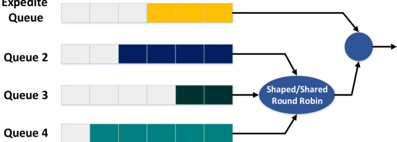
Four egress queues
Different queues can be used to classify and to service the traffic, based on each class specifications. Out of these queues, one can be set as the Expedite queue, a strict priority queue. This means that the Expedite queue will be serviced before any other queue, until the queue has been emptied. After the Expedite queue has been emptied, the other three queues will be dequeued in a Shaped Round Robin or in a Shared Round Robin manner. If shaped mode is selected, then for each of the three queues an amount of bandwidth is reserved. The packets from the three queues are dequeued according to the bandwidth reservation. No packets are sent if the bandwidth reservation has been exceeded. In the Shared Round Robin mode the three queues are also guaranteed a share of bandwidth. If a higher priority queue has some available bandwidth that it is not using and a lower priority queue requires more bandwidth than its reservation, then it can borrow that bandwidth from the queue with unused bandwidth.
Figure 11 – Egress port queueing mechanism of Cisco Catalyst 2960-S
3.3 Model of the network
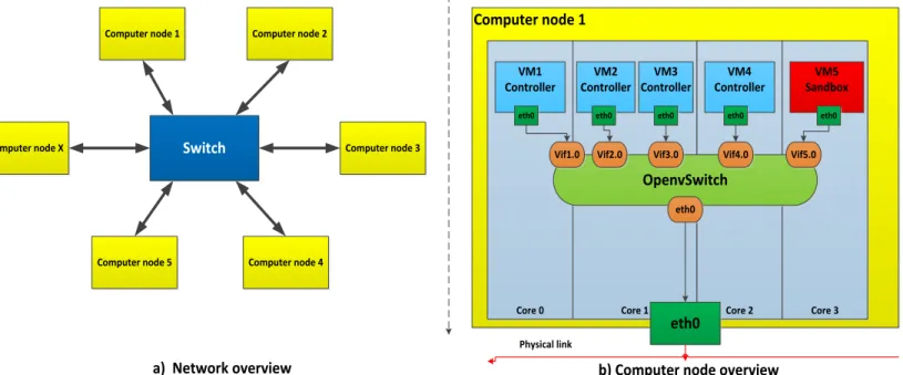
Such a network of software partitions is typical composed of several computer nodes. All the nodes are connected in a star topology using an Ethernet switch and full-duplex links. All the links are considered to be full-duplex, this meaning that an interface can send and receive data at the same time. This solves the collision problem, which is present in other types of links. Figure 12 a) depicts the network topology:
Each of the computer nodes contains:
Several software partitions
One software switch to inter-connect the partitions (OpenvSwitch) Shaped/Shared Round Robin
Expedite
Queue
Queue 2
Queue 3
Queue 4
28
At least one physical Ethernet interface
An internal overview of a typical computer node is shown in Figure 12 b):
Every software partition has one or multiple VCPUs. Inside of a computer node, each VCPUs are pinned to a PCPU (Physical Central Processing Unit). It can be pinned alone or together with other software partitions. On each PCPU, only the VCPUs of the software partitions pinned to that PCPU will be scheduled. The selected scheduling scheme for use as reasoned in section 2.2.2 is called rtpartition. This scheduling scheme implements each VCPU as a deferrable server with a period and a budget. We consider the use of the deferrable servers instead of periodic server because they provide a better utilization of the budget, by preserving the budget until the end of the period. This scheduling scheme also implements a separate RunQueue for each of the physical core on the platform. The other available scheduling scheme is called rtglobal and implements a single RunQueue for all the PCPUs in the systems. In comparison with the other rtglobal, the rtpartition scheme offers a better predictability on how the VCPUs are scheduled, because we know all the other VCPUs that will execute in that core. An overview of the scheduler is presented in Figure 13:
Switch
Computer node 1 Computer node 2
Computer node 3 Computer node 4 Computer node 5 Computer node X a) Network overview Computer node 1
Core 0 Core 1 Core 2 Core 3
VM1 Controller VM2 Controller VM3 Controller VM4 Controller VM5 Sandbox
eth0 eth0 eth0 eth0 eth0
OpenvSwitch
Vif1.0 Vif2.0 Vif3.0 Vif4.0 Vif5.0
eth0
eth0
b) Computer node overview
Physical link
Figure 12- Model overview
29
3.4 Model of the software partitions
The software partitions deployed on each computer node can be divided into two types, based on the type of traffic they transmit and receive:
Controller partition (software partitions with real-time traffic and/or non-real-time traffic of which we have knowledge of)
Sandbox partition (software partition with non-real-time traffic of which we have no knowledge about)
In order to keep the traffic of these two types of software partitions from interfering and to protect the Controller network traffic, the Controller software partitions will be placed in one VLAN (Virtual Local Area Network) network. The Sandbox software partitions will be placed in another VLAN network.
Each Controller software partition can send and receive traffic of the following types:
Controller real-time traffic (high priority traffic)
Controller non-real-time traffic (lower priority than the one of the real-time traffic) The priority of the traffic and the VLAN ID of which the software partition is part of, can both be specified by adding an 802.1q tag to each Ethernet frame transmitted by that software partition. Using this tag it is also possible to specify if the frame can be dropped in case of congestion in the switch. A comparison of a standard Ethernet frame and one which contains the 802.1q tag is depicted in Figure 14:
For each of the Controller software partition the QoS has to be specified based on the priority of the traffic. For the real-time traffic the QoS will be specified at a frame level with the following parameters:
priority of the frame
period of the frame
size of the frame
source MAC address
destination MAC address
For the non-real-time traffic the QoS will be specified at an interface level with the following parameters:
maximum rate (the maximum rate at which the interface can send data)
burst (the amount of data in bytes which the interface can send beyond the maximum rate)
source MAC address
destination MAC address
Preamble Destination
MAC
Source
MAC EtherType Payload CRC
Ethernet frame without 802.1q tag
Preamble Destination
MAC
Source
MAC EtherType Payload CRC
Ethernet frame with 802.1q tag
0x8100 Prio DI VLAN
ID
802.1q tag