Scientific Press International Limited
Dam Safety and Earthquakes
Nasrat Adamo1, Nadhir Al-Ansari2, Varoujan Sissakian3, Jan Laue4 and Sven Knutsson5
Abstract
Earthquakes may cause failure or profound damage for dams. Factors contributing to this are, magnitude on the Richter scale, peak horizontal and vertical accelerations, time duration, in addition to the epicentral distance, nature of foundation rock, criteria of the design, and finally, if appropriate type of dam and materials has been used. Extensive lists of dam failures and damaged once are presented with many case histories. Most failed dams were tailing dams or hydraulic fill dams or small earth fill dams, which reflect the weight of the design and construction factors. Embankment dams, normally, are less tolerant to ground shacking than concrete dams. While rockfill and RCC dams have shown good performance. The developments of design methods and criteria are traced here, from the early use of the pseudoptotic method to the more rational dynamic analysis, which is used nowadays making construction of very large safe dams in seismic regions possible. The method adopts peak ground accelerations from anticipated earthquakes as inputs to the analysis which produce a full spectrum of the factor of safety during any considered event. This has led to increased use of seismic instrumentation to produce seismographs of actual events in the free field, and on dams hit by earthquakes for comparison with outputs of this analysis and for future use for similar dams in similar circumstances, and to decide on rehabilitation measures. The safety levels to which any dam is to be designed are defined in terms of the Maximum Credible Earthquake, Safety Evaluation Earthquake, Maximum Design Earthquake and other similar terms. Dam repairs after sustaining earthquake damages are described in real cases and upgrading of older dams to withstand higher expected seismic events are also treated here and supported by case histories.
1 Consultant Dam Engineer, Sweden.
2 Lulea University of Technology, Lulea, Sweden.
3 Lecturer, University of Kurdistan Hewler, and Private Consultant Geologist, Erbil. 4 Lulea University of Technology, Lulea, Sweden.
5 Lulea University of Technology, Lulea, Sweden.
Article Info: Received: June 9, 2020. Revised: June 18, 2020. Published online: July 10, 2020.
Keywords: Earthquakes, Seismicity, Epicentral Distance, Focal Distance, Peak Horizontal Acceleration, Pseudo-static Analysis, Dynamic Analysis, Maximum Credible Earthquake, Safety Evaluation Earthquake, Maximum Design Earthquake.
1. Earthquakes in General
An earthquake is the shaking of the Earth surface resulting from a sudden release of energy in its crust and its uppermost mantle, which constitute its hard and rigid outer layer, and, therefore, creating elastic waves known as seismic waves. Earthquakes can range in size from those that are so weak that they cannot be felt to that violent enough to toss people around and destroy whole cities. The seismicity, or seismic activity, of an area are the frequency, type, and size of earthquakes experienced over a period of time. Earthquakes and the release of its energy are caused mostly by rupture of geological faults but also by other events such as volcanic activity; landslides, mine blast, and nuclear tests. An earthquake's point of initial rupture deep, down is called its focus or hypocenter, and the epicenter is the point at the ground level directly above the hypocenter. The mechanism of this rupture is attributed to the fact that the upper mantle of the Earth consist of seven or eight major tectonic plates, (depending on how they are defined), and many minor plates, which are in constant motion Figure 1 [1]. Where the plates meet, their relative motion determines the type of boundary: convergent, divergent and transform. Earthquakes, volcanic activity, mountain-building, and oceanic trench formation occur along these plate boundaries (or faults) which form the seismic belts of Earth. The two major seismic belts are the Circum-Pacific Belt, which surrounds the Pacific Ocean, and the Alpine Belt, which stretches from the Azores through the Mediterranean and Middle East to the Himalayas and Indonesia, where it joins the Circum- Pacific Belt. A purely oceanic seismic belt lies along the mid-Atlantic ridge, [2]. Along these belts the majority of earthquakes epicenters cluster, refer Figure 2 [3].
Figure 2: Distribution of Major Earthquakes in the World [3]. The location of any point on the earth surface close to any of these belts indicates high probability of earthquakes occurrence at that point. It is the magnitude of any earthquake, which represents the governing factor for the extent of damage that can happen to structures, whether being dams, buildings, bridges or any other infrastructure or lifeline. Local faults, even not related to these major seismic belts,
can also give rise to earthquake and result in such damages and even loss of life. The obvious conclusion that may be drawn is that, it is the duty of the designing
engineer to ensure the safety of these structures against the impacts of earthquakes by using building codes. In major structures such as dams, Atomic Energy Power Stations and the like, a complete Seismic Study is not only justified but strongly recommended
.
2. History of Dams Failures and Incidents due to Earthquakes
During late history, not many dams have collapsed or very badly damaged worldwide by earthquakes. Most failed dams were tailing dams or hydraulic fill dams or small earth fill dams. Few embankments or concrete gravity dams of significant size have been severely damaged. This good record may be largely due to the fact that few dams have been shaken by earthquakes of duration and intensity sufficient to jeopardize their structural integrity. It is well understood also that the failed dams, especially tailing dams or the small earth dams were not designed or constructed to meet rigid criteria for safety under earthquake loading.In Table 1 a list is given of collapsed dams that have experienced significant earthquake shaking from 1886 to 2000. It includes, where available, principal
earthquake parameters, dimensions and types of dam, epicentral distances. Table 2 lists also dams which were severely damaged (but did not fail) during the same period [4]. Examining these two tables indicates that most of the failed or the seriously damaged dams were tailing dams and/or fill dams of generally low heights and very few large concrete and earth fill dams. The explanation to this is already given.
Apart from the mentioned dams (Tables 3 and 4), there were hundreds of other dams, which had sustained minor damages or not damaged at all which may be referred to in reference [4].
Referring back to these two tables it may be concluded that they infer the fact that dams behave differently in response to earthquake events depending on the strength of the earthquake on the Richter Scale (M), type of the dam and its location relative to the epicenter of the earthquake. Moreover, Table 2 does not give full description of damage and characteristics of the site and more details of the dams themselves. To explain these points some important earthquakes are given hereunder with their impacts on dams within their area of influence for clarification.
3. Important Earthquakes and their Observed Damages on
Earth fill Dams
3.1 General
Studying previous major earthquakes and the damage they left on dams serve to illustrate the possible performance of similar dams in similar future seismic events. The lessons learned from such case histories help designers in selecting the type of dam best suited to the site under consideration, materials for construction and the seismic criteria to be followed in addition to other design details.
Table 1: List of reported dams which failed as a result of earthquake (1896- 2000)[4].
Dam Name Country Type Height [ft] Earthquake name Earthquake Date Magnitude Distance [km]
Augusta USA E - Charleston 13 Aug 1886 7.0 180,0
Vulcano Lake Mexico E 12 Imperial Valley
22 June 1915 5.3 0.0
Fairmont USA E - Imperial
Valley
22 October 1916
5.0 22.0 Sheffield- 2 USA E 25 Santa Barbra 29 June 1925 6.3 11.2
Barahona Chile T 200 Talca 01 October 1928
8.4 160,0 Vulcano Lake Mexico E 12 El Centro 18 May 1940 7.1 0.0
Hosorogi Japan E 28 Fukui 28 January 1948 7.3 4.8
Coleman USA Comp - Fallon 23 August 1954 6.7 24.0
Saguspe USA E - Fallon 23 August 1954 6.7 24.0
Rogers USA M - Fallon 23 August 1954 6.7 80.0
El Soldado Chile T - Chile 28 March 1965 7.1 -
El Cobre Chile T - Chile 28 March 1965 7.1 35.0
Hayagakenuma Japan E 40 Tokachi- Oki 16 May1968 - -
Ichrigoya Japan E 26 Tokachi- Oki 16 May 1968 - -
Gamanosawa Japan E 34 Tokachi- Oki 16 May 1968 - -
Shorey Peru T - Peru 1969 - -
Huachopolca Peru T - Peru 1970 - -
Salamanca Chile T Chile 08 July 1971 7.5 110,0
Illapel Chile T 26 Chile 08 July 1971 7.5 100,0
Cerro Negro Chile T - Chile 08 July 1971 7.5 -
Mochinkoshi 1 Japan T 98 NrIzu- Oshima
14 January 1978 7.0 35
Cerro Negro-2 Chile T 105 Chile 03 March 1985 7.7 -
Veta De Aqua Chile T - Chile 03 March 1985 7.7 -
Upper Koyoen Japan E 30 Kobe 17 January 1995 6.9 -
Central Koyoen Japan E 30 Kobe 17 January 1995 6.9 -
Niteko Japan E - Kobe 17 January 1995 6.9 <10
Shih- Kang Taiwan CG 82 Chi- Chi 17 September 1999
7.6 0.0
Table 2: List of reported dams which were severely damaged (but did not fail) as a result of earthquakes [4].
Major earthquakes, as natural phenomena, have in most cases left behind destruction and life losses, which have led to a considerable number of studies and detailed documentations. One of the important aspects so covered in these documentations is the damages earthquakes have left on dams that were located in their area of influence. It is of interest to note that ICOLD has devoted many of its publications to highlight seismic action on dams together with other national committees on large dams and government agencies.
From following case histories of dams damaged by earthquakes, but did not fail, many serious conclusions can be derived. To follow these case histories in more
details one may refer to references [5] and [6], given in the list of references. In the following some of the important factors contributing to damage suffered by
dams as a consequence of earthquakes, are outlined:
1. The magnitude of damage on dams is generally commensurate with the magnitude of the earthquake. As one example; the 1923 Kanto, Japan`s earthquake (M= 8.2) damaging the 122 feet high Ono earthfill dam. The dam Dam Name Country Type Height
[ft.]
Earthquake
name Earthquake Date M
Distance [km]
Ono Japan E 161 Kanto 01 September 1923 8.2 51.0
Misc. Embankments
Japan E 50/8 Ojka 1939 6.6 -
Hebgen [1] USA E 90 Hebgen Lake 17 August 1959 7.1 16.0 Hsinfengkiang Chile CGB 344 Hsinfengkiang 19 March 1962 6.1 1.1
Bella vista Chile T - Chile 28 March 1965 7.1 55.0
Koyna [1] India CG 338 Koyna 11 December 1967 6.5 3.0
Yeyuan China E 82 Bohai Gulf 18 July 1968 7.2 ?
U. Van Norman
U SA HF 80 San Fernando 09 February 1971 6.5 11.2
El Cobri Chile T - Chile 08 July 1971 7.5 80.0
Lliu Chile T - Chile 08 July 1971 7.5 -
Shimen Ling China E 147 Haicheng 04 February 1975 7.3 33.0 Touho
(Douhe)
China E 72 Tangshan 28 July 1976 7.8 -
Mochinkoshi No2 [2]
Japan T 98 Nr i- O Atssshk 15 January 1978 5.8 -
La Palma Chile T 26 Chile 03 March 1985 7.7 -
Austrian [1] USA E 185 Loma Prieta 17 October 1989 7.1
Masy way [2] Luzon E 82 Philippines 16 July 1990 7.7 19.2 Niwajkumine Japan E ? Hokkaido Nans 12 July 1993 7.8 74
Lower San Fernando
USA HF 125 Northridge 17 January 1994 6.7 9.4 Lower
Koyoen
Japan E 30 Kobe 17 January 1995 6.9 -
Zhong Hai China CG 82 Lijang 03 February 7.0 4.0
was fractured in many places with one vertical fissure extending 70 feet along the puddle clay core and settlement of about one foot in addition to
longitudinal crack on the crest of ten inches width and length up to 200 feet. Similarly, the case of the 1985 Mexico earthquake (M=8.1) which damaged the 197 feet earth rockfill and central clay core La Villita dam, and the 485 feet high el Infiernillo rockfill and earth core dam. Both dams experienced considerable settlements and small permanent deformations. These damages were added to similar damages they both had received in the previous five events between 1975 to 1985, which had magnitudes exceeding 7.0, but without failing. This may be compared with the 1987 Whittier Narrows (M= 6.1) earthquake, which affected many embankment dams in greater Los Angeles area and showed no significant damages as indicated by the strong motion records obtained from this event.
2. The mode of ground shaking during the earthquake may contribute also to the damage produced on structures within the epicentral area, including dams. In the 17th of October 1989 Loma Prieta event, California, USA (M= 7.1), about dozen dams located within the epicentral area withstood the strong ground shaking. This was because the strong phase of shaking (acceleration > 0.05g) during the earthquake lasted less than eight seconds at rock and firm soil sites. 3. It was proved also from documenting various earthquakes that embankment
dams’ behavior during earthquakes in which sound seismic design criteria were used, was relatively better than other dams, as they sustained lesser damages. Good examples may be cited from the 17th September (M=7.4) Koçaeli earthquake in Turkey. This earthquake was caused by the rupture of the northernmost strand of the North Anatolia fault system, which produced seven earthquakes with magnitudes more than 7.0 since 1939. None of the 48 dams located within the area were affected. Two of the dams closest to the area where the recently completed, Yuvaçik Dam, which was about 7km of the earthquake’s epicenter, and the Gokçe Dam, located around 55km to the southwest close to the town Yalova.
Yuvaçik a Dam, a 108m high rock and gravel earth fill and clay core dam was first impounded in June 1998. Its live storage capacity is 55Mm3, and its full capacity is
66 Mm3. Sound seismic design criteria were used for its design by considering
horizontal peak ground acceleration of 0.15g for the dam, and with a lower acceleration used for design of the associated structures. The dam incurred very little damage as a result of this event. The fact that the reservoir was not full was fortunate as the freeboard allowed for wave action, and settlement was only 1.5m. Total settlement before the event measured only 25mm, and following the earthquake the maximum settlement was only 130mm, but it was reported, however, that the tidal wave induced during the event had a height of 2. m. The earthquake resulted in almost negligible horizontal movement of the dam of about 30mm, with the dam recovering to half of this value within weeks from the earthquake.
The Gokçe Dam is an embankment dam 50m high and similar to Yuvaçik Dam, its reservoir was only impounded to half of its full capacity of 25.5Mm3 at the time of
the earthquake and was designed according to the same seismic criteria also. This dam was found to have suffered no obvious damage during the event. The intake structure is similar to that on the larger Yuvaçik Dam, and, while it showed evidence of some cracking; it appeared generally to be very robust.
In another case, on January 7th, 1994 Northridge earthquake (M=6.7), California USA, the earthquake induced ground motions, which were quite severe at 105 dams located within 75km radius of its epicenter. These dams were mostly the same dams shaken in 1971 during San Fernando (M=6.6) earthquake. Eleven earth fill and rockfill dams experienced some cracking and slope movements as a result of the last earthquake, yet none of them presented an immediate threat to life and property. This satisfactory performance may be due to a large extent, from the fact that in California, most significant dams have been reevaluated for the Maximum Credible Earthquake (MCE), during investigations initiated after the San Fernando Earthquake in 1971. Questionable or unsafe embankments have been upgraded or decommissioned, or the owners have been asked to operate with partially full reservoirs with an increased freeboard. In this connection, one of the few embankment dams that suffered noticeable damage from the Northridge Earthquake was the 125-foot high Lower Van Norman Dam, a hydraulic fill dam. The dam had been abandoned as a water storage facility since 1971 San Fernando earthquake, but was still used with empty reservoir for flood control. It experienced two to three and a half inch-wide cracks of several hundred feet long. Some of these cracks were at least five feet deep. Sand boils and a sinkhole were also observed along the upstream face. Maximum crest settlement was eight inches, and maximum horizontal crest movement was about four inches toward upstream. The 82-foot-high Upper Van Norman Dam, which was also left with an empty reservoir since it was severely damaged in 1971 experienced transverse cracks near its right abutment, on the downstream slope, and near its left abutment, which were up to 60 feet long and two to three inches wide. Maximum non-recoverable crest displacements were about 2.4 feet of settlement and over six inches of horizontal upstream movement. It is worth mentioning that the seismicity of the area where the two reservoirs were located was studied by the US Geological Survey in 1974 following the San Fernando earthquake, and the expected earthquakes` motion parameters were obtained and included in a circular of this department [7]. In the same event the 130 foot-high Los Angeles Dam, which has replaced the two Van Norman dams, and located between these two floods controls dry embankments, experienced extensive, but not safety threatening cracking of its asphalt lining and settled 3.5 inches near its maximum section. Maximum horizontal crest movement was about 2.2 inches. Lastly, the Northridge Earthquake caused minor damage in the form of transverse cracks and settlement to Lower Franklin Dam (103 feet high), Santa Felicia Dam (213 feet high), Sycamore Canyon Dam (40 feet high), Schoolhouse Debris Basin Dam (38 feet high), Cogs well Dam (266 feet high), Porter Estate Dam (41 feet high), and Rubio Basin Dam (64 feet high). Adoption of sound and proper design seismic criteria had saved all these dams from failure.
4. Selection of materials of earthfill dams may also contribute greatly to their response to earthquakes. Many earthfill dams were affected by the February 1971 San Fernando earthquake (M= 6.6) which experienced (0.15g) or greater ground shaking. The Lower San Fernando dam, a 140 foot high hydraulic fill dam, performed poorly and was severally damaged. The upstream face and the crest slid into the reservoir leaving only 5 feet of freeboard against
overtopping. Lower Van Norman dam and the Upper Van Norman dam (mentioned also above in relation to 1994 Northridge event) were seriously damaged by this earthquake and were taken out of service as permanent storage dams but remained to serve for flood protection dams as already explained. The first is the hydraulic fill dam, so it experienced a widespread liquefaction and major slope failures. Overtopping did not occur only because the reservoir water level was relatively low when the earthquake struck. The Upper Van Norman dam was also severely damaged.
These cases brought to the attention of engineers the potential vulnerability of embankments constructed of poorly graded, badly compacted and saturated fine sands and silts, and led to significant advance in the numerical methods of dynamic analysis of dams. This also sheds light on the large number of tailing dams’ failures during earthquakes, which result as a consequence of the uniform graded silts or sand of which they are made of, in addition to the low degree of compaction and the high degree of saturation of these materials making them very susceptible to liquefaction.
In contrast to the above mentioned cases, the behavior of Kitamaya Dam in response to the January 17, 1995 Kobe, Japan (M=6.9) earthquake merits mentioning. This dam, an 80-foot high embankment dam was built of decomposed granite of varying gradations with a vertical chimney drain; it was about 31km away from the epicenter of this earthquake. At the time of the earthquake, the reservoir was at the maximum operational level. After the earthquake, reservoir drawdown revealed a 1.0 to 1.5m scarp and bulging at the toe, so test pits were excavated into the slope to determine the condition of the embankment at this location and to obtain samples for testing. Beneath the riprap and gravel bedding was a loose layer of rolled embankment, which was followed by an extremely loose layer that had contained the slide. Unaffected embankment was found below the sliding layer, and the sliding failure zone had a thickness of 1.5 to 2.0m. Undisturbed samples of the embankment above the sliding block were not particularly loose. The damages suffered by the dam were tolerable and repairable mainly because of good selection from the construction materials and degree of compaction. In the same event, no severe damages were observed in earth fill dams higher than 40 feet, which again was explained by the good selection of material and high degree of control during construction. Smaller embankment dams, however, suffered various forms of damages such as longitudinal cracking, transverse cracking, settlement, deformation of the dam body, and up to few complete failures; depending on their materials and construction practices exercised. In spite of the overall assessment of peak acceleration levels at these dams’ locations, which was estimated to be
approximately 0.22g, the limited damages in this event could be partially explained by the fact that they had good rock foundations and give support to what has been mentioned in (3) above, in addition to a good selection of construction material, and good control over construction.
5. In many instances chance has contributed to save many dams, or at least, has helped to reduce damage in many dams. In these cases, the reservoirs of many of these dams were either empty or partially full during the earthquakes, so they were not subjected to the full hydrodynamic forces of water assumed for the design of the dam and its ancillary works such as gates [8].
This matter, taken with the other discussed factors, helped in clarifying the mechanism of dams’ total or partial failures or even reducing the magnitude of the resulting damage. The example of Bhui (M=7.7), India, earthquake which struck
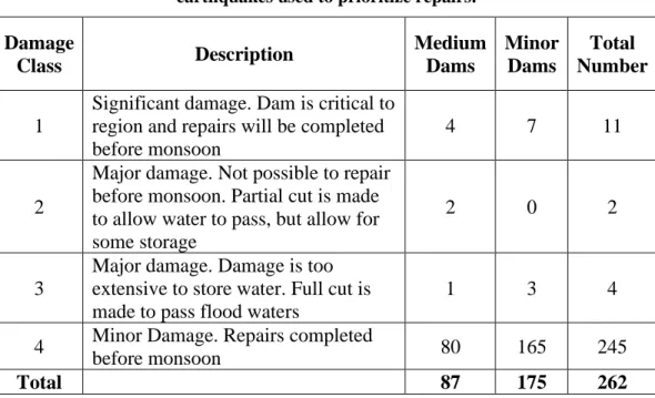
the Gujarat Province on January 26, 2001, can serve as a good example. An important aspect of the Bhuj earthquake was the performance of about 300 small
and moderate size embankment dams (according to ICOLD classification) that were constructed in this region in an effort to store water for irrigation and domestic water supply. All these dams were hit by a/m earthquake. Fortunately, at the time of the earthquake, being the end of the irrigation season, there was very little water in the reservoirs and most of the damage to embankments occurred in the valley section where the low pool kept the alluvium saturated. Following the event, the dams were categorized based on their observed damages, downstream consequences, and their importance to water supply. This classification was used to determine the appropriate course of action and prioritization for restoration. Damage classes and
the total number of dams in each class are summarized in Table 3. Multiple post-earthquake investigators noted liquefaction related damage to
embankments throughout the affected area, as evidenced by sand boils, ground cracking and lateral spreading. Many of these dams were constructed directly on loose alluvial deposits, and this was the reason behind the liquefaction of this material. But the fact that those dams were mostly empty contributed to the low hydrodynamic forces acting on them reducing damages [9].
The damages on these dams were of varying degrees of settlements, bulging of dam body, horizontal displacements, horizontal cracks at the top and upper zones of the dam of various depths and lengths, in addition to vertical cracks and slope slides, but no failures were reported.
Generally Speaking, very high dams, whether zoned earth fillor rockfill dams have responded fairly well during very strong earthquakes when they are designed according to sound seismic criteria using suitable zoned materials. Rockfill dams, or concrete faced rockfill dams, however, showed in many cases superior performances over embankment dams of the same heights under the same conditions. The following examples are of severe events and their impacts on large modern designed, Earth fill and Rockfill dams.
Table 3: Damage classifications of earthen dams resulting from Bhuj 2001 earthquakes used to prioritize repairs.
Total Number Minor Dams Medium Dams Description Damage Class 11 7 4 Significant damage. Dam is critical to region and repairs will be completed before monsoon
1
2 0
2 Major damage. Not possible to repair
before monsoon. Partial cut is made to allow water to pass, but allow for some storage
2
4 3
1 Major damage. Damage is too
extensive to store water. Full cut is made to pass flood waters
3
245 165
80 Minor Damage. Repairs completed
before monsoon 4 262 175 87 Total
The Wenchuan, China, May 12, 2008 (M=8) earthquake, which had struck the 512 foot high Zipingpu concrete faced rockfill dam. This Dam was 7km from the fault break, and it experienced an estimated peak ground acceleration of 0.5 to 0.6g. The crest settled 3 feet damaging small parts of the face slab. Maximum settlement was 760mm. The duration of strong ground motion was up to 120 seconds at sites underlain by deep alluvium.
In this earthquake, all the reservoirs in Sichuan and other seven nearby provinces were damaged. There were about 300 aftershocks some of which were over M=6. The number of earth fill dams which collapsed was 69 dam and there were 331 other highly dangerous situations. Well-built dams, especially rockfill dams, performed as designed[10], [11] and [12]. Nevertheless, the case of Bikou Dam, a 335 foot high earth fill dam with central core, has to be mentioned. It had experienced an
estimated peak ground acceleration of 0.5g in this event, but its crest settled 9 inches only as a result of shaking, which is classified as mild damage [10].
Another very severe earthquake, the Mulue, Chile, February 27, 2010 (M=8.8) had its repercussions on large dams without any of them failing. One Example is Convento Viejo, 105 feet high, embankment dam, which was not damaged even though it experienced a peak ground acceleration of 0.38g, which was higher than what was expected when the dam was designed. At least 16 dams were moderately to severely be shaken with no reported failures. Some non-threatening slope
In the same earthquake, the Coihueco dam a 31 meter zoned earth fill dam suffered non-threatening sloughs on its upstream face and crest cracking apparently without liquefaction occurring [13] and [14].
The Tohoku, Japan, March 11, 2011 earthquake (M=9.0), when more than 400 dams, which were inspected afterwards, generally performed well with minor
or moderate cracking occurring at embankment dams.
The Surikawa, a 172 foot high central core rockfill dam reacted well to this severe event. The dam settled a maximum of 7 inches; transverse cracking of the crest paving occurred near the abutments and the leakage temporarily increased from 18 to 25 gallons/minute. The measured peak horizontal accelerations were 0.11g at the foundation and 0.47g at the crest. The cracks were trenched and found to be only one foot deep.
The second high dam which was subjected to the same earthquake is the Kejauma, which is 79 feet high, central core rockfill dam. This dam experienced peak horizontal accelerations of 0.27 and 0.5g which was recorded at its foundation and crest, respectively. A maximum crest settlement of 6 inches occurred and leakage temporarily increased from 5 to 110 gallons/minute, and transverse cracking of the crest paving were up to one inch wide. A third dam, the Minamikawa Saddle Dam, a 64 foot high asphalt faced rockfill dam. The earthquake caused a temporary increase in leakage from 5 to 23 gallons/minute, a crack in the asphalt face, and a maximum crest settlement of 4 inches. A peak horizontal acceleration of 1.3g was measured at the crest. And, 0.27g was measured on the foundation of the main dam, 1km away. The analysis of accelerations, settlements and leakage increases measurements at these, and the other dams indicated the effects of the long duration of the Mw 9 earthquakes shaking.
An exceptional case, however, maybe that of the Fujinuma Ike dam, a 60 foot high, 436 feet long embankment where records show an inferior performance than the other dams. A preliminary report mentioned flaws in the embankment, such as thick lifts, so the dam may not have been constructed to modern standards. The report confirms the observation of long duration.
4. Important Earthquakes and their Observed Damages on
Concrete Dams
Case histories have shown that concrete dams suffered less damage from earthquakes than embankment dams; this may be due to the nature of these structures, the type of construction material, degree of control exercised during construction, and to the relatively stronger foundations on which concrete dams are normally constructed as compared to their equals of earthfill dams. Apart from Shih- Kang dam, which failed on the 21st of September 1999, Chi- Chi Earthquake (M=
7.6) in Taiwan, no more concrete dams have failed, and this was the first case in history so far [15], [16].
It can be said that the performance of all types of concrete dams has been satisfactory. The Shih-Kang gravity dam experience, however, confirmed that concrete dams are vulnerable to major fault rupture.
Concrete buttresses dams when subjected to severe shaking have developed horizontal cracks at the elevation high in dams where the downstream buttresses intersect the vertical “chimney” section. This is an area where the stiffness of the concrete structures significantly changes.
Major thin arch concrete dam, with a full reservoir, although have performed in a good way, their behavior under peak ground acceleration exceeding 0.5g has yet to be known.
Some other specific conclusions on concrete dams where damage has been identified to indicate; there has been cracking high in the dam and where additional features such as curbs, railings, gates, or guard and/ or control houses are located. Cracking in buttress dams appeared to be due to upstream to downstream motions and not cross-canyon motions. Very little in the way of increased leakage has occurred in concrete dams subjected to major earthquakes. This can be explained, in part, to the fact that any cracking caused by the earthquake has mainly been horizontal and located high in the dam while the reservoir not being full in many cases. Some rock foundations have experienced a temporary increase in seepage following an earthquake which decreased later on.
There may be number of reasons why concrete dams have performed well and invariably better than that predicted.
The main reasons being:
1. Concrete dams are redundant structures that provide considerable capacity to redistribute load once damage occurs in the structure. Being so massive, typically there is plenty of concrete volume around damaged areas of the dam to carry loads around the damaged sections of the dam.
2. The duration of strong shaking may be too short to cause failure. Normally, it takes considerable time at high levels of shaking to cause failure of a medium-thick arch dam compared to a thin arch dam.
3. The dynamic tensile strength of concrete is taken as 50 percent higher than the static tensile strength of concrete. This increase in strength makes dams stronger during seismic shaking and increases resiliency.
4. Damping mechanisms can increase in the dam during the earthquake and reduce the seismic impact on the body of the dam. Damping increases still as the concrete cracks and contraction joints open and close.
5. The seismic impact of earthquake on the dam may be reduced because the natural frequency of the dam may not match the postulated frequency content of the earthquake taken for the design. For example, a gravity dam with a natural frequency of 7 Hz would not align with a ground motion with a peak spectral acceleration at 3 Hz.
6. The three-dimensional effects of the dam help prevent failure. The curvature in plain view of the dam or the narrowness of the canyon greatly increases the
seismic stability of a dam, and the potential for sliding of a gravity dam wedged in a narrow canyon is remote.
The generally accepted potential failure modes for concrete dams during an earthquake are cracking of concrete through the dam that forms removable blocks and sliding of the blocks during or after the earthquake. Severely shaken concrete dams; to date have cracked at locations of change in geometry (re-entrant corners) but have not formed removable concrete blocks. Thus, the entire potential seismic failure mode has not been fully achieved or experienced for concrete dams. While concrete dams are designed to withstand a higher degree of seismic shaking than buildings and have performed well in the past, we should not become overconfident of their performance in the future. Great care should be taken in the design details and quality of construction. Particular attention should be given to possible faults located directly under the dam.
In Shih-Kang gravity dam case, the dam was hit by Chi- Chi earthquake, which was caused from the Chelungpu faulting system rupture. Several concrete gravity and arch dams in the same area were severely shaken during the earthquake but performed satisfactorily. Shih- Kang dam itself could not withstand the earthquake force along the line of the fault crossed the dam itself causing considerable horizontal and vertical displacement, which acutely twisted the body of the dam causing it to fail. This high gravity dam is essentially a 18-bay gated spillway. The fault rupture extended both upstream and downstream of the dam and caused extensive damage to bays 16 to 18 on the right side of the structure[17]. As a general conclusion, it may be said that the performance of concrete dams has been satisfactory [18].
Perhaps hundreds or more concrete dams of all types had been shaken by earthquakes close to the dam sites, but only about 20 had experienced recorded or estimated peak ground accelerations (PGA)s of 0.2g or higher. Up to 2013, some of these dams have experienced Peak Ground Accelerations over 0.3g. The duration of motion of the M=9.0 Tohoku Earthquake was extraordinary long lasting from 150 to 300 seconds. Following the earthquake, about 240 concrete dams were inspected, and reports indicated that concrete dams appear to have performed very well during the main earthquake and numerous large aftershocks. One publication in 2017 gives a summary of concrete large dams that were shaken by a peak horizontal ground acceleration of more than 0.3g, Table 4. Peak accelerations at the crest were greater with full reservoirs, as expected. According to type, they were as follows:
Table 4: Number of Concrete Dams subjected to PHGA> 0.39 g showing type and corresponding damage [18].
To demonstrate the relatively satisfactory performance of concrete dams, few reprehensive cases of all types are briefly described below to illustrate this point. Examples of Concrete Gravity Dams:
1. Lower Crystal Springs Dam, this dam, a 127 foot high curved gravity dam hit by the San Francisco 1906 (M=7.9) Earthquake, but suffered no
damage, although it was located only 0.25 miles from the San Andreas Fault. This dam also was been moderately shaken by the 1989 Loma Prieta (M=7.1) event without suffering damage.
2. Koyna Dam, India, this dam, a 338 foot high straight gravity dam was shaken by the 1967 Koynanagar (M=6.7) earthquake, which occurred near Koynanagar town close to dam site. The earthquake claimed at least 177 lives and injured over 2,200. The dam itself developed substantial longitudinal cracking at the top. Damage was attributed to design or construction details that would be avoided in modern structures[19]. 3. Takou Dam, Japan, this is a (77m) 252 feet high straight gravity dam
completed in 2006 which underwent the Tohoku 2011 (M=9) event and the following week (M=7.1) aftershock. In spite of the peak horizontal ground acceleration during the main shock which was estimated at 0.40g, the dam showed no damage except of an offset in the dam parapet wall and cracking of the wall of the gate house. This multipurpose dam had about half full reservoir during the main shock[20].
Examples of Concrete Arch Dams:
1. Gibraltar Dam, USA, this is a constant radius concrete arch dam 194.5 feet (59.3m) high and 600 feet (180m) long. It was severely shaken by the 1925 Santa Barbara Earthquake (M=6.3). The estimated Peak Horizontal Ground Acceleration (PHGA) was a greater than 0.30g. The dam; however, suffered no damage. The dam was strengthened in 1990 by additional supporting RCC weight on the dam downstream face, which, in effect, changed the dam from concrete arch dam to a curved gravity dam [18].
2. Pacoima Dam, USA, this is a 372 foot high concrete arch dam. It was shaken by the 1971 San Fernando Earthquake (M=6.6) and again in 1994 Northridge Earthquake (M=6.7). In the first event, a peak horizontal ground acceleration
Dam Type Number Damage to dam No Damage to dam Minor Damage to dam
A Gravity 10 (1 RCC) 1 5 4
B Arch 6 (1 RCC) 1 2 3
C Buttress 2 2 0 0
D Spillway 1 1 0 0
of 1.25g was recorded on rock at left abutment, slightly above the dam crest. The depth of the reservoir at the time of this event was 60% of its impounding depth. It did not develop structural cracks or relative movements between adjacent blocks, but the left abutment had to be strengthened using post tensioned tendons to stabilize two large rock wedges that moved several inches as a result of the earthquake. In the 1994 event, the dam experienced ground acceleration also well above 1.0 g near the top of the same abutment. During this event, the reservoir was about one-third of its impounding depth. The dam suffered minor damages including movement of the joint between the left abutment block by 0.5 inch, and the opening of the left end of the dam by about two inches, while one location at the left abutment was displaced horizontally by 19 inches and a rock mass was displaced by 14 vertically in another location.
3. Rapel Dam, Chile, this is a double curvature arch dam 364 feet high and 886 feet long that was hit by two earthquakes. The first was the 1968 Santiago earthquake (M=7.8), and the second was the 2010 Maule (M=8.8) earthquake. Prior to the first event, a swarm of 300 earthquakes of lesser magnitude occurred. Measured peak free-field accelerations near the dam were 0.31g in the cross- canyon direction, 0.14g in the upstream to downstream direction, and 0.11g vertical. The arch dam did not experience any damage, but the appurtenant structures did have some damages. The spillway walls were cracked and there was leakage through the wall of the right spillway. The upper part of one intake tower cracked and separated from the dam. In the 2010 Maule earthquake, the reservoir was full, and measurements showed that the peak horizontal acceleration at the site was 0.3g. One concrete block of the dam at the left abutment of the dam which was next to the fault “Nido de Aquila” showed a rise of 0.02 inches. Seepage again increased along the right abutment; this time from normal 3.4gal/sec to 10.6gal/sec, and some concrete pavement at the dam crest cracked.
Examples of Concrete Buttress Dams:
1. Hsinfengkiang Dam, China, this is a 344 foot high buttress dam, which was shaken by the nearby earthquake of (M=6.1) in 1962. The dam developed substantial longitudinal cracking near the top, but damage was attributed to design and construction details that were avoided in modern structures.
2. Sefid Rud Dam, Iran, this is a 388 foot high buttress dam which was hit by the 1999 Manjil Earthquakes (M=7.4). It suffered severe cracking in the upper part of some buttresses and other forms of damages. It was rehabilitated and remained in services. Some 20 years later, a blister on the steel lining in the elbow of one of the two morning glory spillways in the left abutment appeared, and the increased leakage led into the discovery of previously unnoticed damage caused by the previous earthquake [17].
Examples of Rolled Compacted Concrete (RCC) Dams:
1. Shapai Dam, China. This is a 132m high RCC arch dam which was
moderately shaken by the Wenchuan (M=8) in 2008. The dam withstood this event without damage to its body.
2. Miyatoko Dam, Japan. This is a 157 foot high RCC dam which was hit by the Tohoku (M= 9.0) earthquake of 11 March, 2011. The dam was located
approximately 13km north of Sendai in Miyagi, area where the peak horizontal ground acceleration was greater than 0.7g. A strong motion instrument located in the gallery recorded peak horizontal ground acceleration of 0.32g during this earthquake. No damage was recorded for Miyatoko and Takou Dams, and possibly others in Japan, will need to be confirmed at a later date [17].
5. Seismic Design Criteria for Large Dams
Large concrete dams were among the first structures for which seismic analysis and design had been performed. The seismic analysis method that was originally developed by Westergaard in the 1930s for the Hoover Dam has found worldwide acceptance among designers of concrete dams (Westergaard, 1933) [21]. This relatively simple pseudo-static analysis method accounts for both the inertial effects of the dam body and the hydrodynamic pressure acting on the vertical upstream face of a dam. It was a common practice to use a seismic coefficient of 0.1, corresponding to a horizontal force equals to the weight of the dam times a ground acceleration of 0.1g. The USBR, depending upon the size of the dam and the seismic risk, however, used seismic force which was assumed to range from 0.05 to 0.15 times the weight of the structure. For larger dams, the bureau combined horizontal acceleration effects with a vertical component, which was 50 percent of the horizontal acceleration; the assumed directions of the two components were those most unfavorable to structural stability. Most large dams design in countries other than USA adopted similar criteria. For example, Bhakra Dam in India, a 740-foot-high concrete gravity structure located about 180km from the epicenter of the Richter magnitude (M=8.6) Kangra earthquake of 1905, was designed for a lateral force coefficient of 0.15 and a vertical force coefficient of 0.075. The U.S. Army Corps of Engineers practice required the use of seismic coefficients for sliding and stability analyses of concrete dams and structures. Hydrodynamic pressures also were considered by similar methods in some cases[22]. The pseudo-static analysis method, however, proved in many cases to be unsatisfactory as it did not meet many seismic modes of ground shaking and ground acceleration. This method has therefore been replaced by the Dynamic Response Analysis, especially for large dams. Today, the seismic safety of dams is assessed based on typical failure modes and the inelastic deformations of dams due to ground shaking, and the evaluation of earthquakes. In this approach, the seismic design criteria for large dams defines many levels of safety, as per the magnitude of the earthquake obtained from the seismic history of the area, and depending on the importance of the dam or related structures, as follows:
Maximum Credible Earthquake (MCE): It is the event which produces the largest ground motion expected at the dam site on the basis of the seismic history and the seismo-tectonic setup in the region. It is estimated based on deterministic earthquake scenarios. According to ICOLD, the ground motion parameters of the MCE shall be taken as the 84 percentiles (mean + one standard deviation).
Maximum Design Earthquake (MDE): For large dams, the return period of the (MDE) is taken as 10,000 years. For dams with small and/ or limited damage potential, shorter return periods can be specified. The (MDE) ground motion parameters are estimated based on a probabilistic seismic hazard analysis (PSHA). According to ICOLD, the mean values of the ground motion parameters of the (MDE) shall be taken. In the case where a single seismic source (fault) contributes mainly to the seismic hazard, uniform hazard spectra can be used for the seismic design. Otherwise, based on the disaggregation of the seismic hazard (magnitude versus focal distance) different scenario earthquakes may be defined.
Safety Evaluation Earthquake (SEE): The SEE is the earthquake ground motion which a dam must be able to resist without uncontrolled release of the reservoir. For major dams, the SEE can be taken either as the (MCE) or (MDE) ground motions. Usually, the most unfavorable ground motion parameters have to be taken. If it is not possible to make a realistic assessment of the (MCE); then the (SEE) shall be at least equal to the (MDE). The (SEE) is the governing earthquake ground motion for the safety assessment and seismic design of the dam and safety-relevant components, which have to be functioning after the (SEE).
Design Basis Earthquake (DBE): The (DBE) with a return period of 475 years is the reference design earthquake for the appurtenant structures. The (DBE) ground motion parameters are estimated based on a (PSHA). The mean values of the ground motion parameters of the (DBE) can be taken. Noting that the return period of the (DBE) may be determined in accordance with the earthquake codes and regulations for buildings and bridges in the project region.
Operating Basis Earthquake (OBE): The (OBE) may be expected to occur during the lifetime of the dam. No damage and/ or loss of service must happen. It has a probability of occurrence of about 50 % during the service life of 100 years. The return period is taken as 145 years. The (OBE) ground motion parameters are estimated based on a (PSHA). The mean values of the ground motion parameters of the (OBE) can be taken.
Construction Earthquake (CE): The (CE) is to be used for the design of temporary structures; such as coffer dams and considers the service life of the temporary structure. There are different methods to calculate this design earthquake. For the temporary diversion facilities, a probability of exceedance of 10% is assumed for the design life span of the diversion facilities. Alternatively, the return period of the
(CE) of the diversion facilities may be taken as that of the design flood of the river diversion. The MDE, DBE, OBE and CE ground motion parameters are usually determined by a probabilistic approach (mean values of ground motion parameters are recommended), while for the (MCE) ground motion deterministic earthquake scenarios are used (84 percentile values of ground motion parameters shall be used). However, for the MDE, DBE, OBE and CE also deterministic scenarios may be
defined. If reservoir-triggered seismicity (RTS) is possible; then the (DBE) and (OBE)
ground motion parameters should cover those from the critical and most likely (RTS) scenarios as such events are like to occur within years after the start of the impounding of the reservoir.
The different design earthquakes are characterized by the following seismic Parameters:
1. Peak ground acceleration (PGA) of horizontal and vertical earthquake
components. 2. Acceleration response spectra of horizontal and vertical earthquake
components typically for 5% damping, i.e. uniform hazard spectra for (CE), (OBE), (DBE) and (MDE) obtained from the probabilistic seismic hazard analysis (mean values), and 84 percentile values of acceleration spectra for (MCE) obtained from the deterministic analysis using different attenuation models.
3. Spectrum-compatible acceleration time histories for the horizontal and vertical components of the (MCE) ground motion determined either from a random process or by scaling of recorded earthquake ground motions. The artificially generated acceleration time histories of the horizontal and vertical earthquake components shall be stochastically independent. To account for aftershocks, it is recommended to increase the duration of strong ground shaking.
In case of fault movements, similar estimates are required for the ground shaking. It appears that it is quite difficult for dam designers to get quantitative estimates of fault movements for the different types of design earthquakes. So, they are justified in such cases to use simplified load and analysis models that lead to a safe design, even if the load model does not comply fully with the real nature of the earthquake ground motion.
Considering the Appurtenant Structures of dams, these may be assigned to the safety level to which they belong with respect to the safety of the whole dam as follows: Safety class 1: All elements related to the safe control of the reservoir, i.e.Bottom outlets and spillways are defined as safety-critical or safety relevant elements; they shall be designed for (SEE) and OBE (serviceability).
Safety class 2: All structures and components related to power production (penstock, power intake, powerhouse, tunnels, caverns, turbines, switchyard, transmission lines etc.), water supply, irrigation, navigation etc.; they shall be
designed for (DBE) with high importance factor or according to earthquake building code as minimum requirement for the region under consideration.
Safety class 3: Other items which can easily be replaced/repaired when damaged and whose failure has acceptable consequences; they shall be designed for (DBE) or according to earthquake building code, [23], [24], [25] and [26].
6. Seismic Hazards and Their Impacts on Dam Safety
During the planning and design stage, safety of the dam may be ensured as far as seismicity is concerned by concentrating the study on certain seismic factors, which are the following:
Proximity of Site to fault Lines
The selection of the most appropriate type of dam may be affected by its distance from a known fault line. In a known fault zone, the possibility of existence of some branches from the main fault line should be given serious consideration. The Shih- Kang concrete gravity dam (Barrage) already discussed happened to be located on a branch of a main fault which had spectacular horizontal and vertical displacements during the 1999 Taiwan earthquake that resulted from the rupture of this fault causing failure of the dam. It is questionable; however, if any other type of dam could have endured this severe displacement, which had occurred in this case. Avoiding altogether such site for building a dam would have been the safest solution if the existence of such a fault was confirmed beforehand. Fault movement in the dam foundation or discontinuities in dam foundation near major faults can be activated, causing structural distortions [27].
In the case of Rubar Lorestan Dam at the Zagros Mountains in western Iran, the site was only 1.6km from the Saravand- Baznavid Fault. The main recent fault is thought to have moved about 50km in the last 3-5 million years implying a horizontal slip rate of 10–17mm/yr, and it was the source of frequent earthquakes of M=6 to M=7 earthquakes. The peak ground acceleration at the dam site was calculated using seven different attenuation formulae, and it varied from 0.52g to 0.61g. After long discussions as to whether a rockfill dam might be better able to resist fault movement than the rolled compacted (RCC) dam, but possibly it would be much more expensive than RCC dam as it would need spillway tunnels through the abutments whereas spilling water could have been routed over an RCC dam at little extra cost. The decision was to build the cheaper RCC dam even that the Rockfill dam is a little safer[28].
Liquefaction
Liquefaction is a phenomenon in which the strength and stiffness of a soil are reduced by earthquake shaking or other rapid loading. Liquefaction and related phenomena have been responsible for tremendous amounts of damages in historical earthquakes around the world.
Liquefaction occurs in saturated soils, that are soils in which the space between individual particles is completely filled with water. This water exerts a pressure on the soil particles that influences how tightly the particles themselves are pressed together. Prior to an earthquake, the water pressure may be relatively low. However, earthquake shaking can cause the water pressure to increase to the point where the soil particles can readily move with respect to each other. The previous concepts apply to any earth retaining structures that is in contact with water and located in seismic regions, such as an earth fill dam. Liquefaction, therefore, is a serious potential problem for dams built on or with low density, saturated sands. In such cases, liquefaction potential may exist either in the embankment material itself, or
in the foundation alluvial (in case the dam is resting on soil), and/or the abutment. The crest of the 40m high Lower San Fernando Dam settled 8.5 meters in the 1971
earthquake which had a magnitude of 6.6. The dam was built of hydraulic fill, which is particularly vulnerable to liquefaction, because of the low density of the fill. Fortunately, the water level was about 11m below the crest before the earthquake, but only 1.5m of badly cracked material remained after the event. 80,000 people living downstream of the dam had to be evacuated. The 8m high Sheffield dam failed completely in the magnitude 6.3 Santa Barbara event of 29 June, 1925. The dam and its foundation were silty sand, and some experts have blamed the failure on liquefaction of these materials. Krasnodar Dam in Russia near to the Black Sea is 11.5km long and built of hydraulic fill. It holds 2,914Mm3 in a reservoir with an
area of 413km2. A seismic study was carried out by Swiss Experts who
recommended improved drainage at a cost of 56 million USD. The cost of failure, if happened, would have cost an estimated 3 billion USD at the time (about 2000). Tailings Dams have a particularly bad record with hundreds killed in various liquefaction failures in Chile. One example from the Dominican Republic is the 84m high Las Mejitas tailing dam, which holds 48 million tons of very acidic tailings at the Pueblo Viejo gold mine, only 35km from the Septentrional-Orient Fault Zone (SOFZ), where the estimated (MCE) at the site is 0.5g. It was reported that there was lack of adequate zoning in the dam and further studies were recommended for the dam in 2002.
Under seismic action, liquefaction of the tailings which would be denser than water, seems to be possible, [28], [29], [30] and [31].
Seiches
Some authors consider that reservoir oscillation due to ground shaking, and the following seiches are of lesser importance on dam safety than cases of ground shaking itself, which may cause vibrations in the dams and its appurtenant structures and equipment, or from fault movements in the dam foundation causing structural
distortions, and also fault displacement in the reservoir bottom causing water waves or loss of freeboard; or even mass movements into the reservoir resulting from landslides causing impulse waves in the reservoir. Some other authors, on the hand, give examples of some serious cases of seiche which might have been caused by resonance of water in reservoirs that were disturbed by seismic activity acting on dams, [28].
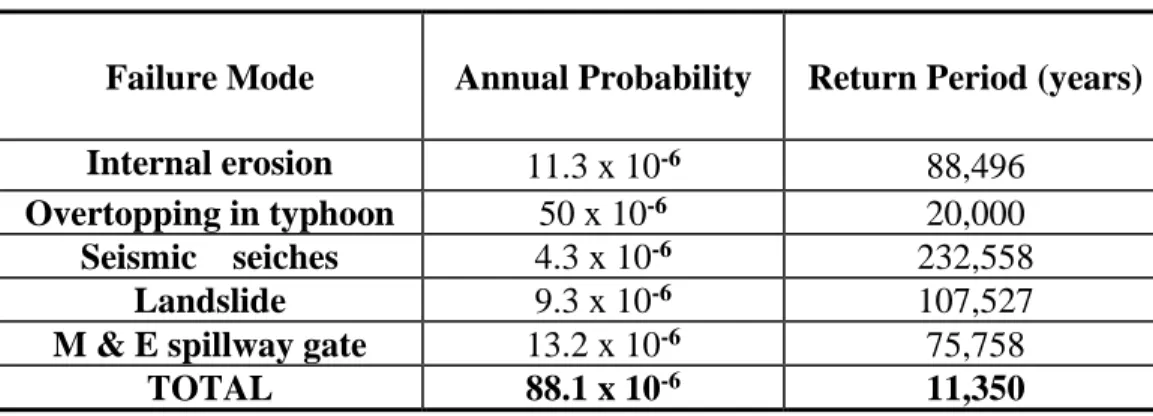
A preliminary risk analysis was completed recently of two dams in Japan. One of them, a 131m high dam, settled 30mm in an M=7 earthquake in 1961. The probability of failure of the two dams as a direct result of an earthquake was shown to be negligible even though a seismo-genic fault passed only 250m from the right abutment of one of them. Moreover, the analysis indicated that the chance of seismic seiches and seismically induced landslides into the reservoir causing displacement wave and overtopping of the dam was also low. The calculated probability of dam failure from seismic seiches has been checked with previous dam failure statistics, and it looked that such probability was very low as compared to other modes of failures; as seen from Table 5.
Table 5: Estimated annual probabilities for the principal modes of failure.
Failure Mode Annual Probability Return Period (years)
Internal erosion 11.3 x 10⁻⁶ 88,496
Overtopping in typhoon 50 x 10-6 20,000
Seismic seiches 4.3 x 10⁻⁶ 232,558
Landslide 9.3 x 10⁻⁶ 107,527
M & E spillway gate 13.2 x 10⁻⁶ 75,758
TOTAL 88.1 x 10⁻⁶ 11,350
Two cases of near failure as result of seiches are the Yuvaçik Dam, Turkey, in the 1999 earthquake and the Hebgen concrete-cored earth fill dam in Montana in the 1959 earthquakes. In the first case, the amplitude of the seiche was about 5m but the reservoir was not full at the time so there was no overtopping. If the reservoir had been full there could have been up to 1.68m overtopping at the abutments and 0.25m at the center of the dam. In the 35m high Hebgen dam, the reservoir was full at the time. This seiche was caused by fault movements crossing the reservoir rather than by ground shaking. A few minutes after the first shock, the caretaker had rushed to the dam and, in the moonlight observed the reservoir action from the high ground above the right abutment. The first waves had already overtopped the dam before he arrived. A few minutes later, another wave struck the dam with such momentum that water one-meter-deep ran uniformly over the crest for 10 minutes. Subsequently, the wave receded and seemed to travel to the other end of the reservoir. After 10 minutes it returned, and water flowed over the crest for another 10 minutes’ period. This action was repeated and although the estimates of depths
and durations are approximate, there can be no doubt that the water flowed over the dam at least four times causing some damage, but the dam did not fail. The magnitude of the earthquake was 7.5 to 7.8 with one of the main faults passing within 215m of the dam.
Landslide
Landslides can form real hazard to populations in mountainous areas, where relatively unstable masses of rock and earth may slide down in mass and hit communities living below causing real havoc by destroying houses and structures and burying people. Triggering of these landslides may be initiated by rainfall causing saturation of the soil mass and its sliding over the surface of a weak surface within. Such failure can also happen as a consequence of seismic ground shacking resulting from an earthquake, especially when such weak potential plain of failure exists [33] and [34]. If such landslide occurs into the reservoir of a dam, then there is a chance that overtopping, and failure of the dam will follow causing destruction and human fatalities downstream. Details and summary of landslides associated with dams and resulting fatalities are given by Professor David Petley from Durham University in a presentation given in the 2013 through an International Conference held in Padua in 2013 on Vajont (1963) incident entitled “Landslides and Large Dams”. The presentation examines losses associated with large dams in the last few years and shows in particular, that there have been over 500 deaths in landslide-related accidents during dam projects [35]. This presentation was followed after about one month by a blog written by the same author giving some more details [36]. In a paper entitled “Global Losses from Land Slides Associated with Dams and Reservoirs”, it is stated also that the risk of landslides can be exasperated by the seismic activity resulting from impounding large reservoirs known as Reservoir Induced Earthquakes (RTS). From the technical perspective, it may be said that seismic activity can profoundly alter the rates of activity of the landside, such that conditions that apply during a site investigation phase may no longer be current later on [37]. Research work, however, has also shown that seismically triggered landslides can affect dams. One particular study indicated that the behavior of an earth dam may depend on the probability of landslide slipping in its reservoir. Despite previous studies which have been done on the landslides without dynamic analysis, this study has investigated the effect of landslide impacting on earth dam during an earthquake. It showed that safety factor during an earthquake for earth dams decreased approximately by 40 percent, and the probability of landslide and its undesirable effects on the earth dams in the presence of reservoir water increased significantly [38]. Another study has concluded that moderate to large earthquakes can trigger landslides, and these landslides commonly cause a significant proportion of total earthquake damage. The ability to predict slope stability during earthquakes
is especially important for seismic hazard analysis of dam projects [39]. Earthquake hazard is multi- sided for large storage dams. Recent earthquakes have
different ways, but those which are related to landslides alone can be listed among these, as in the following:
1. Rockfalls causing damage to gates, spillway piers cracking, retaining walls overturning, surface powerhouses cracking and puncturing, and various damages to electro-mechanical equipment, penstocks, switchyards, transmission lines, etc.
2. Mass movements of landslides and rockfalls into the reservoir causing impulse waves and overtopping of dams.
3. Mass movements blocking rivers and forming landslide dams and lakes whose failure may lead to overtopping of downstream run-of-river power plants or the inundation of powerhouses and the electro-mechanical equipment.
4. Mass movements blocking access roads to dam sites and appurtenant structures [40].
Landslide problem in relation to dam safety has been extensively studied on selected case histories treating it according to, landslide type, rock fall; including talus deposits, problems encountered due to interaction between dams and landslides, and mitigation measures to stabilize such as landslide.
USGS in its professional paper “Interaction of Dams and Landslides-Case Studies and Mitigation”, published in 2006 presented very good information on landslides [41]. Although this publication does not treat seismic triggered landslides with respect to dam safety, but it gives extensive general information on landslides in relation to dams as such.
Generally, it can be said from the foregoing that the probability of dams’ failure resulting from seismically triggered landslides is very remote. Failure probability of dams caused by landslides is shown to be 9.3 x 10⁻⁶ as already indicated from
Table 5. If this probability is coupled with the probability of occurrence of an earthquake which is strong enough to cause such a landslide, then the resulting probability of failure of the dam becomes very remote indeed.
7. Reservoir Triggered Seismicity (RTS)
One important issue associated with the question of dams’ safety is the phenomenon
of Reservoir Triggered Seismicity (RTS). This phenomenon is not fully-understood,
but basically what happens is this; when a dam is built and the reservoir filled with water, the amount of pressure exerted on the earth in that area changes dramatically. When the water level of a reservoir is raised, the pressure on the underlying ground increases, and when the water level is lowered, the pressure decreases. This fluctuation can stress the delicate balance between tectonic plates in faults beneath the surface, possibly causing these plates to shift. Another factor is the water itself; when the water pressure increases more of it is forced into the ground, accordingly, filling cracks and crevices. This water pressure can expand those cracks and even create new tiny ones in the rock causing greater instability below ground. What is more is, as the water sinks deeper, it can act as sort of a
lubricant for rock plates that are being held in place by friction alone. The lubrication can cause those plates to slip [42].
The sure fact is the dam cannot cause an earthquake all by itself. The risk factors, specifically unstable fault lines, have to be there already. With the right conditions in place, a dam can trigger the event earlier than would have happened naturally, and perhaps even increases its magnitude, which is why it is so dangerous to build a dam over a known fault.
A Study case of (RTS) may be cited here, as an illustration; this is the case of Danjiangkou reservoir. The study explains the various factors contributing to trigger the seismicity which had begun after impounding this reservoir in 1967 in Henan and Hubei provinces in central China. The Danjiangkou dam was built in 1958, and impoundment of the 174.5 × 10⁸ m3 capacity reservoir began on 5 November 1967. The originally designed height of the dam was 97m, making the impounded reservoir one of the larger man-made lakes in Asia. As the source of Middle Route of South-to-North water diversion in China, the height of the dam was supposed to be increased to 111.6m starting in 2005 to be completed in 2010. Tectonically, there are four major Paleozoic deep regional crustal faults that crisscross in the reservoir area. They are overlain by about 4 to 5km thick sedimentary cover. Below the sedimentary cover, the crustal thickness varies from 33 to 34 km in the east, to about 37 to 41km in the mountainous area to the west. The deep crustal faults in the reservoir area are: Danjiang, Junyun, and Gonglu and Hanjiang faults. The study confirms that this tectonic setting is responsible for the (RTS) induced in the area. The increased load of the reservoir has caused compressive stresses on the bottom of the reservoir which can destabilize the underlying faults, and form approximately 150KPa tensile stresses in horizontal direction on the surface within the periphery of the reservoir, which might help to open small shallow fractures and promote the permeation of water into deeper rocks. This suggests that the induced seismicity in the reservoir area is mainly attributable to water and migration along the Danjiang and Junyun faults [43]. Other studies have also shown that the reservoir triggered an earthquake is linked to dams higher than about 100m, to large reservoirs (capacity greater than 500 x 106m3), rate of reservoir filling, and to new dams of
smaller size located in tectonically sensitive areas. This means that the causative fault is already near to failure conditions and so the added weight stresses and pore pressures propagation due to reservoir impounding, can trigger the seismic energy release.
1. The detection of the reservoir induced seismicity may be performed in two phases: The first phase includes study of historical seismicity and surveys of the reservoir and surrounding geological structures, aiming at identification of possible active faults.
2. Second phase is carried out, starting at least one or two years prior to
impounding, with the installation of a permanent network of seismometers and precise levelling beacons and use of instrumentation to detect active fault movements, in addition to carrying out reservoir slope stability studies.
![Figure 1: The Earth’s tectonic plates. (Source: USGS) [1].](https://thumb-eu.123doks.com/thumbv2/5dokorg/4426851.106499/2.813.168.649.719.985/figure-earth-s-tectonic-plates-source-usgs.webp)
![Figure 2: Distribution of Major Earthquakes in the World [3].](https://thumb-eu.123doks.com/thumbv2/5dokorg/4426851.106499/3.813.143.674.114.502/figure-distribution-major-earthquakes-world.webp)
![Table 1: List of reported dams which failed as a result of earthquake (1896- 2000)[4]](https://thumb-eu.123doks.com/thumbv2/5dokorg/4426851.106499/5.813.58.758.147.775/table-list-reported-dams-failed-result-earthquake.webp)
![Table 2: List of reported dams which were severely damaged (but did not fail) as a result of earthquakes [4]](https://thumb-eu.123doks.com/thumbv2/5dokorg/4426851.106499/6.813.47.768.148.663/table-list-reported-dams-severely-damaged-result-earthquakes.webp)
![Table 4: Number of Concrete Dams subjected to PHGA> 0.39 g showing type and corresponding damage [18]](https://thumb-eu.123doks.com/thumbv2/5dokorg/4426851.106499/15.813.60.756.146.320/table-number-concrete-dams-subjected-showing-corresponding-damage.webp)
![Table 6: Examples of dams with induced seismicity [44].](https://thumb-eu.123doks.com/thumbv2/5dokorg/4426851.106499/26.813.52.764.278.623/table-examples-dams-induced-seismicity.webp)
![Figure 3: Recommended dam seismic instrumentation [45].](https://thumb-eu.123doks.com/thumbv2/5dokorg/4426851.106499/28.813.152.660.481.871/figure-recommended-dam-seismic-instrumentation.webp)
![Figure 4: Earthquake Inspection Criteria – Simplified Model [47].](https://thumb-eu.123doks.com/thumbv2/5dokorg/4426851.106499/31.813.169.648.176.690/figure-earthquake-inspection-criteria-simplified-model.webp)
