School of Innovation Design and Engineering
V¨
aster˚
as, Sweden
Thesis for the Degree of Master of Science in Computer Science
-Software Engineering 30.0 credits
AUTOMATED SYNTHESIS OF
MODEL COMPARISON
BENCHMARKS
Lorenzo Addazi
lai15004@student.mdh.se
Examiner: Jan Carlson
M¨
alardalen University, V¨
aster˚
as, Sweden
Supervisor: Antonio Cicchetti
M¨
alardalen University, V¨
aster˚
as, Sweden
from failure to failure
with no loss of enthusiasm.
WINSTON CHURCHILLAbstract
Model-driven engineering promotes the migration from code-centric to model-based software devel-opment. Systems consist of model collections integrating different concerns and perspectives, while semi-automated model transformations generate executable code combining the information from these. Increasing the abstraction level to models required appropriate management technologies supporting the various software development activities. Among these, model comparison represents one of the most challenging tasks and plays an essential role in various modelling activities. Its hardness led researchers to propose a multitude of approaches adopting different approximation strategies and exploiting specific knowledge of the involved models. However, almost no support is provided for their evaluation against specific scenarios and modelling practices. This thesis presents Benji, a framework for the automated generation of model comparison benchmarks. Given a set of differences and an initial model, users generate models resulting from the application of the first on the latter. Differences consist of preconditions, actions and postconditions expressed using a dedicated specification language. The generator converts benchmark specifications to design-space exploration problems and produces the final solutions along with a model-based description of their differences with respect to the initial model. A set of representative use cases is used to evaluate the framework against its design principles, which resemble the essential properties expected from model comparison benchmark generators.
Table of Contents
1 Introduction 5 1.1 Problem Formulation . . . 5 1.2 Thesis Contribution . . . 6 1.3 Thesis Outline . . . 6 2 Research Methodology 7 3 Background 9 3.1 Model Comparison . . . 9 3.1.1 Matching . . . 9 3.1.2 Differencing . . . 10 3.1.3 Evalution . . . 113.2 Design Space Exploration . . . 12
3.2.1 Model Generation . . . 12
3.2.2 Model Adaptation . . . 12
3.2.3 Model Transformation . . . 13
4 Benji – A Model Comparison Benchmark Generator 14 4.1 Design Principles . . . 14
4.2 Overall Architecture . . . 15
4.3 Trace Representation . . . 15
4.4 Benchmark Specification . . . 17
4.4.1 Difference Specification Language . . . 17
4.4.2 Benchmark Specification Language . . . 18
4.5 Difference-Space Exploration . . . 19
4.6 Output Construction . . . 21
5 Evaluation 22 5.1 Simplified Ecore . . . 22
5.2 Metamodel Refactorings Catalog . . . 22
5.2.1 Push Down Attribute . . . 24
5.3 Design Principles . . . 25
6 Discussion 28
7 Related Works 29
8 Conclusion 31
List of Figures
1 Research Methodology . . . 7
2 Model Comparison – Overview . . . 9
3 Simple Family – Metamodel and Models . . . 10
4 Model Differencing – Operation-based vs. State-based . . . 10
5 Model Generation Pattern . . . 12
6 Design-Space Exploration – Model Adaptation Pattern . . . 12
7 Design-Space Exploration – Model Transformation Pattern . . . 13
8 Benji – Overall Architecture . . . 15
9 Trace Representation – Metamodel . . . 15
10 Trace Representation – Created Element . . . 16
11 Trace Representation – Deleted Element . . . 16
12 Trace Representation – Preserved Element . . . 16
13 Trace Representation – Changed Element . . . 16
14 Difference Specification Language – Metamodel . . . 17
15 Benchmark Specification Language – Metamodel . . . 18
16 Benji – Output Construction . . . . 21
17 Push Down Attribute – Structural Description . . . 24
18 Push Down Attribute – Difference Model . . . 25
19 Completeness – Initial Model . . . 25
20 Completeness – Expected Difference Combinations . . . 26
21 Pseudo-Randomness – Initial Model . . . 26
22 Visibility – Initial Model . . . 27
23 Minimality – Initial Model . . . 27
Listings
1 Trace Representation - VQL Patterns . . . 162 Rename Person - Difference . . . 17
3 Rename Person - Precondition . . . 18
4 Rename Person - Action . . . 18
5 Rename Person - Postcondition . . . 18
6 Family Benchmark Specification . . . 19
7 Simplified Ecore Metamodel [1] . . . 22
8 Universal Quantifier – Example Pattern . . . 23
9 Push Down Attribute – Difference . . . 24
10 Push Down Attribute – Precondition . . . 24
11 Push Down Attribute – Action . . . 24
12 Push Down Attribute – Postcondition . . . 25
13 Completeness – Benchmark Specification . . . 26
14 Pseudo-Randomness – Benchmark Specification . . . 26
15 Visibility – Conflicting Differences . . . 27
16 Minimality – Benchmark Specification . . . 27
List of Tables
1 Comparison Results – Negatives and Positives . . . 112 Model Generation Frameworks – Design Principles Comparison . . . 19
3 Evaluation – Metamodel Refactorings Catalog . . . 23
1
Introduction
Model-driven engineering (MDE) is a software development methodology promoting the migra-tion from a code-centric to a model-based approach. Tradimigra-tional software engineering practices consider models as mere documentation artefacts whom main purpose consists in facilitating the communication among stakeholders, i.e. descriptive models [2]. The most important artefact of the development process consists of executable code, which is manually produced and maintained coherent with the other artefacts. In a model-driven approach, instead, the system under devel-opment is represented as a collection of models either focusing on different concerns or providing information about the existing relationships between distinct views, i.e. prescriptive models [2]. Models assume the role of first-class artefacts throughout the development process, whereas the executable code of the system is (semi-)automatically generated combining the information from these [3].
Increasing the abstraction level from source code to models required a review of the available tools and methods supporting the various software development activities. For this reason, model management and evolution techniques have been subject to intense research in the recent years [4]. Model comparison, i.e. the identification of the differences existing among models, represents one of the most challenging tasks and plays a crucial role in various modelling activities [5]. Detecting, analysing and understanding the correspondences between different versions of the same model is fundamental when evolving systems and exploring design alternatives [5, 6]. Model comparison also provide an essential support to maintain consistency among different views of a system when adopting a multi-view approach [7]. Moreover, performing model comparison represents the ini-tial step of the model transformation development process [8] and could also be used in model transformation testing, i.e. comparing the produced model with the expected one [7, 9].
The comparison process is generally decomposed in two phases, i.e. matching and differenc-ing [10]. Among these, the intrinsic complexity of model comparison results from the matchdifferenc-ing process [11]. Considering software models as typed graphs, indeed, determining the correspon-dences between model elements can be reduced to solving an instance of the graph isomorphism problem [7], which is known to be NP-Hard [12]. Therefore, the various methods proposed in the lit-erature represent different attempts to provide an approximate solution exploiting structural [8, 13], language-specific [14, 15] or domain-specific [7, 16] knowledge of the involved models [6, 17].
“There is no single best solution to model matching but instead the problem should be treated by deciding on the best trade-off within the constraints imposed in the context, and for the particular task at stake.”
– Kolovos et al. [11]
1.1
Problem Formulation
Researchers and practitioners need support to systematically evaluate model comparison methods with respect to specific application domains, languages or modelling practices. Unfortunately, the large number of model comparison approaches corresponds to the almost complete absence of sup-port for their systematic evaluation. Despite being possible to find manually defined benchmarks, e.g. [18] and [19], these do not provide a plausible solution for every use case as modelling lan-guage, application domain, applied differences and their representation are fixed. Furthermore, the design rationale is often not accessible and potentially biased, which makes the results unreliable and irreproducible. Reusing existing models, instead, would still require the careful identification and representation of the differences existing among these. The assessment of model comparison algorithms thus becomes a time-consuming and error-prone task requiring combined knowledge about the modelling languages, application domain and comparison algorithms in analysis.
The main objective of this thesis consists in providing support to researchers and practitioners for the definition of domain-specific model comparison benchmarks through an automated pro-cedure. In particular, the procedure relies on design-space exploration techniques inspired by its successful application to automate similar model management tasks [20]. Given a set of difference specifications and an input model, users are able to generate a specified number of mutants re-sulting from the application of the first to the latter. For each mutant model, a description of the
applied changes is also generated. In order to achieve the main objective, the research process is driven by the following research questions:
RQ1 What kind of information is required for the specification of differences between models?
RQ2 How can we formulate the creation of model comparison benchmarks as design-space exploration problem?
RQ3 How can we represent the applied differences supporting their adaptation accord-ing to the requirements of an arbitrary comparison algorithm in analysis without loss of information?
1.2
Thesis Contribution
Understanding what kind of information is involved in the specification of differences among mod-els (RQ1) required researching the state-of-the-art in model comparison approaches with specific focus on their matching technique. The obtained findings served as basis for the design of an op-erational notation representing differences in terms of preconditions, actions and postconditions. Preconditions and postconditions consist of assertions describing properties of the involved model elements before and after their modification, respectively. Actions, instead, contain the actual imperative edit statements applied on the involved models.
Formulating the creation of model comparison benchmarks as design space exploration prob-lem (RQ2) required gathering information related to design space exploration techniques in model-driven engineering. The following step consisted in developing a design space exploration formu-lation, i.e. input, output, objectives, constraints, state-coding. The remaining research ques-tion (RQ3) required reviewing model difference representaques-tion techniques focusing on their expres-sive power and support for subsequent model manipulations.
Integrating the obtained results produced a framework for the systematic generation of model comparison benchmarks – Benji. In order to evaluate the framework against its desired proper-ties, an illustrative benchmark construction example has been designed and reproduced using a prototype implementation based on the Eclipse Modelling Framework [21] and Viatra-DSE [22].
1.3
Thesis Outline
The remainder of this thesis is structured as follows. Section 3 introduces the reader to the
fundamentals required for a clear understanding of the problem, its challenges and the solution proposed in this thesis, i.e. model comparison and design-space exploration in model-driven en-gineering. Section 2 illustrates the research methodology followed throughout the thesis process. Section 4 presents Benji, a framework for the generation of domain-specific model comparison benchmarks. The discussion is decomposed with respect to its input, output and execution. Sec-tion 5 presents a proof-of-concept implementaSec-tion of the framework based on the Eclipse Modelling
Framework [21] and Viatra-DSE [22]. The implementation is then evaluated against an illustrative
example readapting well-known metamodel refactorings from [23] on a simplifed version of the
Ecore metamodel [1]. Section 7 compares our contribution with related works in the literature
either addressing the assessment of model comparison algorithms or generating models with user-defined properties. Section 8 concludes the thesis summarising the obtained results and possible future directions.
2
Research Methodology
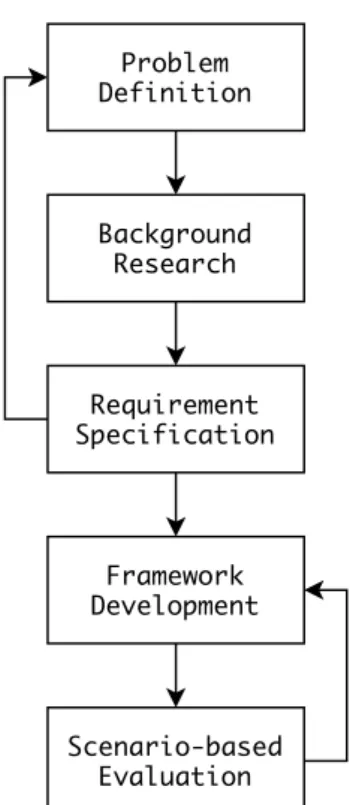
The main objective of this thesis consisted in providing support to researchers and practitioners in the creation of model comparison benchmarks through a systematic procedure based on design space exploration. The procedure is designed to integrate information related to specific application domains, modelling languages or differences, while maintaining a clear separation of concerns enabling reusability and extensibility of the generated benchmarks. According to the classification proposed in [24], the main contribution of this thesis falls within the “procedures and techniques” category. The thesis work proceeded following an adapted implementation of the engineering design process, an iterative decision-making workflow supporting engineers in creating products [25], as illustrated in Figure 1. Problem Definition Background Research Requirement Specification Framework Development Scenario-based Evaluation
Figure 1: Research Methodology
The research process started defining the problem of interest. An initial and broad definition of the problem emerged from previous experiences in extending a model comparison method [16] and found confirmation after a quick investigation of the existing literature addressing the assessment of model comparison algorithms [26, 27]. During the problem definition phase, the main objective consisted in producing a clear definition of the problem and the research questions that needed to be answered – Section 1.
The research questions narrowed the thesis scope and acted as guidance during the background research phase. In this, contributions related to model comparison and design space exploration techniques in model-driven engineering have been researched using the snowball method [28] – Section 3.
The acquired knowledge supported the requirement specification phase, where expected func-tionalities and qualities for a systematic procedure supporting the creation of model comparison benchmarks have been defined. Using the specified requirements, the following step consisted in building a design space exploration, i.e. input, output, objectives, constraints, state-coding, and architecting a framework integrating the formulation while abstracting its technical details – Sec-tion 4.
An illustrative example has been designed considering functional and extra-functional require-ments, and reproduced using a prototype implementation of the framework based on the Eclipse
the appropriateness of the framework, as well as analysing its limitations. Possible functional defects resulted in re-iterating the framework development activities.
Despite being common to validate procedures and techniques using examples [24], this approach introduces threats over the generalisability of the obtained results. In order to manage this risk, the illustrative scenarios have been designed exclusively considering the identified requirements, hence aiming to prove properties and functionalities not depending on the specific technologies and languages in use. As discussed in Section 8, evaluating the framework on large-scale industrial case studies is planned for the near future.
3
Background
This section introduces the essential concepts underlying the main contribution of this thesis. The discussion starts with an overview of model comparison, its composing activities, the different approaches proposed in the literature and common evaluation techniques. The section concludes introducing design-space exploration in model-driven engineering along with common integration patterns in the literature.
3.1
Model Comparison
Model-driven engineering promotes the migration from a code-centric to a model-based approach to cope with the increasing complexity of modern software systems development. Domain-specific modelling languages are defined using meta-models and used to create models focusing on different aspects of the system under development. Models assume the role of first-class citizens through-out the development process [3]. The information from multiple models is integrated into other artefacts and kept consistent using automated model transformations. Complex software system development is realised through chains of increasingly platform-specific transformations from high-level models to source code. In this context, disposing of efficient techniques detecting model-high-level differences represents a fundamental requirement for numerous activities spanning throughout the development process, e.g. model versioning [6], model transformation testing [9] and (meta)model co-evolution [7].
The existing approaches can be distinguished in two categories with respect to the number of models involved in the comparison process, i.e. two-way and n-way techniques. Intuitively, the first class groups all approaches limiting their comparison process to two models, i.e. initial and current, whereas the latter support comparisons involving an arbitrary number of models. The following discussion focuses on two-way model comparison approaches.
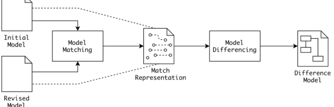
Given two models, model comparison algorithms produce a difference model illustrating the changes among these. As depicted in Figure 2, the comparison process is decomposed in two phases – matching and differencing [10]. Initially, all elements from the first are linked with the corresponding ones in the latter. Then, a difference model is constructed processing the identified correspondences.
Model
Matching DifferencingModel
Difference Model Revised Model Initial Model Match Representation
Figure 2: Model Comparison – Overview
3.1.1 Matching
Given two models, the matching phase consists in mapping the elements from the first with the corresponding ones in the latter. Each mapping might involve multiple elements from one model or the other, and provide a discrete or continuous numerical value indicating the plausibility of their correspondence. Considering their matching criteria, the existing approaches can be grouped in four categories – identity-based, signature-based, similarity-based and language-specific algorithms [11]. Identity-based and signature-based techniques associate model elements with persistent or dy-namically generated unique identifiers, respectively. In this context, the matching criteria simply
consists in mapping elements having the same identifier and their similarity value is discrete, i.e. whether the related identifiers correspond or not.
Similarity-based matching algorithms compare model elements using dedicated similarity func-tions on their structural features, e.g. name, references or attributes. Unlike the previous ap-proaches, mappings are associated with continuous values, hence elements from one model might correspond to multiple elements from the other, i.e. partial matches.
Language-specific algorithms extend the previous approaches exploiting semantic information concerning specific application domains or modelling languages to optimise their matching process.
3.1.2 Differencing
Given a match representation, model differencing algorithms translate the identified mappings into meaningful change descriptions. The existing techniques can be grouped in two categories –
operation-based and state-based.
Operation-based notations represent changes in terms of edit primitives applied on the initial model, whereas state-based approaches construct declarative descriptions focusing on the visible changes in the final model. In other words, operational approaches describe how model elements changed, while state-based approaches focus on what changed.
In order to illustrate the difference between these approaches, let us consider the following small example metamodel and two conforming model instances – Figure 3. A simple Family metamodel is defined in the upper part, whereas the two different instances are represented in the bottom. Comparing these, the name attribute value of the Family instance f1 is changed from ”family1” to ”Doe”, the Person instance p1 is deleted and another Person instance p2 is created with name attribute value equal to ”John”.
Family name:String Person name:String p1:Person name="person1" p2:Person name="John" f1:Family name="Doe" f1:Family name="f1"
Figure 3: Simple Family – Metamodel and Models
Edit Scripts represent a well-known metamodel-independent operational approach involving
primitives to create, delete and update elements – new, delete, set, insert, remove [5]. The notation presented in [29], instead, provides an example of state-based approach. Given a metamodel, an extended metamodel supporting the representation of modified model elements is automatically derived. For each metaclass Class, three corresponding metaclasses are generated representing created, deleted and changed instances, respectively – ChangedClass, CreatedClass, DeletedClass. The left and right side of Figure 4 illustrate the operation-based and state-based representation of the existing differences between left-side and right-side models in Figure 3, respectively.
updated p1:DeletedPerson name="person1" p2:CreatedPerson name="John" f1':Family name="Doe" f1:ChangedFamily name="f1" SET (f1, name, "family1", "Doe")
CREATE (p2, Person) INSERT (f1, members, p2) SET (p2, name, null, "John") REMOVE (p2, members, p1) DELETE (p1, Person)
3.1.3 Evalution
Given the essential role played within various model management activities, the concept of qual-ity of model comparison algorithms is relative and the evaluation criteria used to assess their results depend on the specific use case [27]. For example, an algorithm producing low-level dif-ferences might result convenient in semi-automated workflows, e.g. model transformation testing. Inversely, the same differences could result hardly readable and inconvenient in tasks involving human interaction and reasoning, e.g. manual conflict resolution in model versioning.
Regardless of the evaluation criteria, model comparison algorithms are generally assessed con-structing ad-hoc benchmarks consisting of triples of models hM1, M2, ∆M1→M2i where M1 is the
initial model, M2represents a possible modified version of M1and ∆M1→M2acts as oracle
describ-ing the actual changes applied on M1 in order to obtain M2.
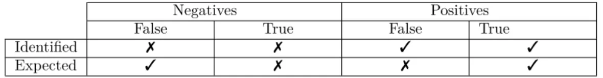
Given a model comparison benchmark, the expected differences and the actual results produced by an algorithm in analysis can be partitioned into four categories – false negatives, true negatives,
false negatives, true negatives – as illustrated in Table 1. Negatives are differences that have
not been identified during the comparison process, whereas positives consists in differences that
have been identified. Both partitions are further decomposed in true and false depending on
their correctness with respect to the expected differences. False positives, for example, represent identified differences that were not supposed to be detected, while true positives consist in expected differences that were successfully identified.
Negatives Positives
False True False True
Identified 7 7 3 3
Expected 3 7 7 3
Table 1: Comparison Results – Negatives and Positives
Although an established definition of quality for model comparison algorithms still does not exist, the current evaluation approaches share a common concept of correctness concerning the pro-duced results. In practice, the correctness of model comparison algorithms is quantified adapting fundamental metrics from the field of information retrieval on positives and negatives – precision,
recall and f-measure (Equation 1–3). In particular, precision and recall compute the percentage
of correct differences over all the proposed and the expected ones, respectively. Finally, f-measure combines precision and recall into a single harmonic mean value.
P recision = |{T rue P ositives}|
|{T rue P ositives}| + |{F alse P ositives}| (1)
Recall = |{T rue P ositives}|
|{F alse N egatives}| + |{T rue P ositives}| (2)
F − M easure = 2 · P recision · Recall
P recision + Recall (3)
Complex and application-specific evaluation criteria might be defined over positives and nega-tives, as well as precision and recall. For example, the overall metric in [30] is defined to measure the effort required in order to align the results produced by a given comparison algorithm with the expected ones, i.e. adding false negatives and removing false positives. Intuitively, this metric aims to measure the effectiveness of a given model comparison algorithm within a model versioning workflow.
Overall = Recall · (2 − 1
3.2
Design Space Exploration
Design-Space Exploration is an automated search process where multiple design alternatives satis-fying a set of constraints are discovered and evaluated using goal functions. Numerous approaches exploiting design-space exploration techniques have been proposed and succesfully applied in differ-ent domains, e.g. model merging [31], software security [32], circuit design [33, 34], embedded sys-tems development [35, 36]. In practice, three main classes of approaches integrating model-driven engineering with design-space exploration techniques have been identified – Model Generation,
Model Adaptation and Model Transformation [37]. The main differences among these approaches
regard the input artefacts, the adopted exploration techniques and the required expertise about the problem and the application domain.
3.2.1 Model Generation
The model generation pattern generates models conforming to an input metamodel while satisfying user-defined constraints expressed using a dedicated notation. The design-space exploration is re-duced to solving a constraint satisfaction problem over models [38]. Figure 5 illustrates the pattern. Depending on the solver, metamodels and constraints are transformed using the expected problem formulation notation (A). The candidate solutions produced by the solver (B) are evaluated using user-defined goal functions and transformed into the initial or another modelling formalism (C). The exhaustive search performed in approaches implementing this pattern might result compu-tationally inefficient. Therefore, initial metamodel instances might be used to impose additional constraints narrowing the search space from the beginning.
Figure 5: Model Generation Pattern
3.2.2 Model Adaptation
Approaches implementing the model adaptation pattern execute meta-heuristic search algorithms on ad-hoc search representations built from a set of initial models. Figure 6 illustrates the pattern. The specific search representation depends on the problem domain and search algorithm (A). Dur-ing the exploration process, candidate solutions are generated applyDur-ing user-defined manipulations on the initial search model. Global constraints prune the exploration process discarding invalid intermediate solutions, whereas goal functions are used to evaluate their optimality (B). The ob-tained solutions might be transformed conforming to the initial or another formalism (C). The user is required to provide model manipulations, global constraints and goal functions expressed using dedicated notations. This allows explicit integration of domain-specific knowledge.
3.2.3 Model Transformation
Unlike the previous ones, the approaches implementing the model transformation pattern directly use the original input models throughout the design-space exploration process. Candidate solu-tions are obtained using user-defined model transformation rules, which selection criteria depends on the specific application. Figure 7 illustrates the pattern. Each candidate solution is validated against multiple global constraints along with the corresponding sequence of applied transformation rules (A). The output models are generally represented using the initial model notation and ob-tained selecting the candidate solutions optimising the result of the user-defined goal functions (B). The approaches implementing this pattern require deep knowledge about the specific problem and application domain. Furthermore, the efficiency and correctness of the exploration process strongly depends on the user-defined transformation rules and the trace representation formalism in use.
4
Benji – A Model Comparison Benchmark Generator
This section presents the Benji model comparison benchmark generation framework, main contri-bution of this thesis. The framework consists of a domain-specific language for the specification of model comparison benchmarks and its interpreter. The discussion starts illustrating the design principles and overall architecture of the framework, then focusing on how models are represented and the features characterising the domain-specific language. Finally, the section concludes illus-trating how the generation process is implemented using design-space exploration techniques and the output models are constructed starting from the obtained solutions.
4.1
Design Principles
In order to guide the development process, a set of fundamental properties concerning the sys-tematic generation of model comparison benchmarks has been defined. These properties concern both the specification formalisms provided to the user, the generation process and the represen-tation of the final results. Configurability has been defined reviewing the existing contributions proposing benchmarks for model comparison algorithms and extracting the essential configuration features that a benchmark generation framework must provide to users. Completeness,
Pseudo-Randomness, Minimality and Visibility, instead, have been defined analysing the characteristics
and limitations of the existing model generation approaches and languages. The first two principles represent recurring concerns in the existing literature on model generation techniques, as discussed in Section 7. The remaining principles, instead, have been defined observing the limitations of the existing model generation approaches. Adaptability has been defined investigating the various difference representation approaches used in the existing model comparison algorithms.
Configurability – Model comparison benchmarks are constructed aggregating triples, each con-sisting of an initial model, a modified version and a description of the differences among these. Therefore, the framework must allow to indicate the initial model and the differences to apply in order to obtain the modified versions. Furthermore, users must be able to indicate a minimum and maximum number of times each difference is expected to be applied, the number of modified models to generate and the location where to store these.
Completeness – Given a benchmark specification, the generation process must explore the complete solution space. More specifically, the framework must generate models considering all possible combinations of differences and their respective minimum and maximum number of ex-pected applications.
Pseudo-Randomness – The users must be able to indicate the number of times a given differ-ence is expected to be applied. However, it must not be possible to select the specific instance in case the same difference would be applicable multiple times. Throughout the generation process, the framework must mitigate the risk of introducing biases selecting the difference application to perform using a pseudo-random criteria.
Minimality – Duplicated models do not provide additional value to model comparison bench-marks. Therefore, the framework must ensure no duplicated models are generated. In particular, in case the same modified model could be obtained applying multiple sequence of difference ap-plications, model comparison algorithms would select the shortest combination. Therefore, the framework must only keep the shortest sequence of difference applications for each duplicated model.
Visibility – Applying a given difference might might overwrite previous difference applications involving common model elements. Despite being applied, the previous difference would potentially be impossible to detect in the generated model. The framework must handle possible overlapping and conflicting differences throughout the generation process.
Adaptability – The generated models must be adaptable to evaluate model comparison al-gorithms using different notations and data granularity to represent their results. The applied
differences must be represented using a low-level and model-based notation allowing its conver-sion to algorithm-specific notations using semi-automated transformations and without requiring external information to be integrated.
4.2
Overall Architecture
The overall architecture of the framework is illustrated in Figure 8. Model comparison benchmarks are specified in terms of initial models and expected differences using a dedicated domain-specific language. Given a benchmark specification, the generation process can be decomposed in two phases – (A) difference-space exploration and (B) output construction.
During the difference-space exploration phase, the information from a given benchmark speci-fication is processed and used to build and solve a corresponding design-space exploration problem instance. Further details on the formulation construction process are provided in Section 4.5.
Once concluded the exploration process, the obtained solutions are translated into the corre-sponding pair of output model and difference representation. Aggregating the generated pairs with the initial model produces a model comparison benchmark complying with the initial specification. The output construction process is further detailed in Section 4.6.
The Benji framework implements the model adaptation pattern presented in Section 3.2.2. Goal functions, model manipulations and global constraints are extracted from benchmark specifications during the difference-space exploration phase, whereas candidate solutions are transformed into output models during the output construction phase.
Initial Models Benchmark Specification Difference-Space Exploration Modified Models Difference Representation A B uses uses uses
Figure 8: Benji – Overall Architecture
The framework is designed targeting the Eclipse Modelling Framework (EMF), a de-facto stan-dard modelling platform for both academic and industrial projects [21]. However, its fundamental concepts and mechanisms abstract from implementation details and specific technological choices.
4.3
Trace Representation
Manipulating and reasoning about changing model elements throughout the generation process requires an appropriate formalism providing access to their current state while maintaining a read-only representation of their initial state. In Benji, such notation is implemented wrapping model elements into trace objects and splitting their representation into an initial and a current version as illustrated in Figure 9.
ecore::EObject initial
current Trace
Three possible states can be identified for model elements – created, deleted and preserved. In the first case, the corresponding trace representation consists of a trace object linked to the current model element version. The initial version, instead, is unset to indicate that the model element does not exist in the initial model, as illustrated in Figure 10.
:EObject current :Trace
Figure 10: Trace Representation – Created Element
Similarly, deleted model elements are represented as trace objects linked to the initial model element version. The current version, instead, is unset indicating that the model element does not exist in the current model version, as illustrated in Figure 11.
:EObject initial :Trace
Figure 11: Trace Representation – Deleted Element
Finally, preserved model elements consist in elements that existed in the initial model version and continue to exist in the current version. Intuitively, the corresponding trace representation consists of a trace object linked to an initial and current model element instance, as illustrated in Figure 12.
:EObject initial :Trace current :EObject
Figure 12: Trace Representation – Preserved Element
Edit operations are directly applied on the current model element version. Therefore, changes involving attributes and references are represented comparing initial and current version of a given model element. Figure 13 provides an example of renamed model element, i.e. where the name attribute value has been changed.
:Person name = "John"
initial :Trace :Person name = "Jim" current
Figure 13: Trace Representation – Changed Element
In the current framework implementation, model element properties in preconditions and post-conditions are expressed using the Viatra Query Language (VQL). The patterns describing created, deleted and preserved model elements using their trace representation are illustrated in Figure 1.
In these, trace initial and trace current identify the initial and current model element version links, respectively. The find operator is used to check a given assertion and neg to represent negated conditions. /* C r e a t e d - e l e m e n t o n l y e x i s t i n g in the c u r r e n t m o d e l */ p a t t e r n c r e a t e d ( trace , c u r r e n t ) { neg f i n d t r a c e _ i n i t i a l ( trace , _ i n i t i a l ); f i n d t r a c e _ c u r r e n t ( trace , c u r r e n t ); } /* D e l e t e d - e l e m e n t o n l y e x i s t i n g in the i n i t i a l m o d e l */ p a t t e r n d e l e t e d ( t r a c e : Trace , i n i t i a l : E O b j e c t ) { f i n d t r a c e _ i n i t i a l ( trace , i n i t i a l ); neg f i n d t r a c e _ c u r r e n t ( trace , _ c u r r e n t );
/* P r e s e r v e d - e l e m e n t e x i s t i n g in b o t h i n i t i a l and c u r r e n t m o d e l */ p a t t e r n p r e s e r v e d ( t r a c e : Trace , i n i t i a l : EObject , c u r r e n t : E O b j e c t ) {
f i n d t r a c e _ i n i t i a l ( trace , i n i t i a l );
f i n d t r a c e _ c u r r e n t ( trace , c u r r e n t ); }
Listing 1: Trace Representation - VQL Patterns
4.4
Benchmark Specification
In Benji, two domain-specific languages are provided to define model comparison benchmarks and differences, respectively. These languages are built on top of existing technologies and designed to fulfil the configurability and visibility properties discussed in Section 4.1. The remainder of this section provides a description of the languages, while also illustrating their current implementation.
4.4.1 Difference Specification Language
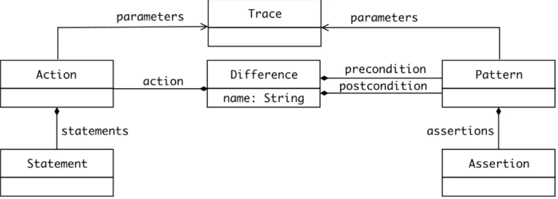
Fulfilling the visibility principle requires the framework to provide means to express differences before and after their application, in addition to the actual modifications to perform. In this context, the visibility of a given difference can be verified ensuring that the corresponding post-condition is fulfilled in the current model. In order to provide this support, a dedicated difference specification language is defined in Benji. Figure 14 illustrates the main concepts of the language. Model differences are represented in terms of actions, preconditions and postconditions. An action consists of imperative statements representing the actual modifications to perform whenever the corresponding difference is applied, whereas precondition and postcondition consist of assertions describing the involved model elements before and after the difference application, respectively.
Difference name: String Pattern Action postcondition precondition action Statement Assertion statements assertions parameters parameters Trace
Figure 14: Difference Specification Language – Metamodel
The difference specification language is implemented as embedded domain-specific language in Xtend, a flexible and expressive dialect of Java [39]. Preconditions and postconditions are expressed using the Viatra Query Language (VQL), a domain-specific language for the specification of patterns over EMF models [40].
As illustrative example, let us consider the difference renaming a Person instance conforming to the Family metamodel presented in Section 3.1, as illustrated in Listing 2. Each difference specification starts with a unique name attribute, whereas precondition, action and postcondition are specified referencing the corresponding external definitions.
let r e n a m e P e r s o n = d i f f e r e n c e . n a m e (" r e n a m e P e r s o n ") . p r e c o n d i t i o n ( b e f o r e R e n a m e P e r s o n ) . a c t i o n ( d o R e n a m e P e r s o n ) . p o s t c o n d i t i o n ( a f t e r R e n a m e P e r s o n ) . b u i l d
Actions, preconditions and postconditions of the renamePerson example difference specifica-tion can be defined using trace objects, as illustrated in Listing 3–4. The difference involves a single Person instance, represented by the person parameter in precondition, postcondition and action. Intuitively, the precondition consists in finding a preserved person instance, which name property has not been changed before, i.e. initial and current value correspond (Listing 3). Given a person instance fulfilling the precondition, the action updates its current name attribute value, e.g. prepending a constant string to its initial value (Listing 4). Once applied the action, the postcondition still expects the involved person instance to be preserved, while also requiring its current name to be different from the initial (Listing 5).
p a t t e r n b e f o r e R e n a m e P e r s o n ( p e r s o n : T r a c e ) { f i n d p r e s e r v e d ( person , i n i t i a l _ p e r s o n , c u r r e n t _ p e r s o n ); f i n d p e r s o n _ n a m e ( i n i t i a l _ p e r s o n , i n i t i a l _ n a m e ); f i n d p e r s o n _ n a m e ( c u r r e n t _ p e r s o n , c u r r e n t _ n a m e ); i n i t i a l _ n a m e == c u r r e n t _ n a m e ; }
Listing 3: Rename Person - Precondition
let d o R e n a m e P e r s o n = [ T r a c e p e r s o n |
p e r s o n . c u r r e n t . n a m e = " c h a n g e d " + p e r s o n . i n i t i a l . n a m e ]
Listing 4: Rename Person - Action
p a t t e r n a f t e r R e n a m e P e r s o n ( p e r s o n : T r a c e ) { f i n d p r e s e r v e d ( person , i n i t i a l _ p e r s o n , c u r r e n t _ p e r s o n ); f i n d p e r s o n _ n a m e ( i n i t i a l _ p e r s o n , i n i t i a l _ n a m e ); f i n d p e r s o n _ n a m e ( c u r r e n t _ p e r s o n , c u r r e n t _ n a m e ); i n i t i a l _ n a m e != c u r r e n t _ n a m e ; }
Listing 5: Rename Person - Postcondition
4.4.2 Benchmark Specification Language
Fulfilling the configurability principle requires the framework to provide support for the specifi-cation of model comparison benchmarks in terms of initial models and differences with minimum and maximum number of expected applications. Furthermore, users must be able to specify the maximum number of generated models and the location where to store these. In order to pro-vide this support, a dedicated benchmark specification language is defined in Benji. Figure 14 illustrates the main concepts of the language. Benchmark instances represent model comparison benchmark specifications and consist of an initial model and a set of bounded differences. The ini-tial model is referenced using its resource location, whereas bounded differences refer to an existing difference specification and allows to specify a lower and upper bound on the number of expected applications. Finally, benchmark instances also provide support to specify the maximum number of generated models and their storage location.
Benchmark outputFolder: String maxInstances: Int BoundedDifference lowerBound: Int upperBound: Int Model uri: String differences models difference Difference
Figure 15: Benchmark Specification Language – Metamodel
b e n c h m a r k . m o d e l (" pa t h / to / i n i t i a l / m o d e l ") . d i f f e r e n c e (0 , 2 , r e n a m e P e r s o n ) . d i f f e r e n c e (1 , 1 , d e l e t e P e r s o n ) . d i f f e r e n c e (0 , 1 , c r e a t e P e r s o n ) . b u i l d . g e n e r a t e (ALL, " p a t h / to / o u t p u t / f o l d e r ")
Listing 6: Family Benchmark Specification
The benchmark specification integrates three differences, i.e. renamePerson, deletePerson and
createPerson. The first corresponds to the difference illustrated in the previous section, whereas
the remaining ones describe the creation and deletion of Person instances into Family instances, respectively. Each difference is associated with minimum and maximum number of expected ap-plications, e.g. renamePerson is optional and can be applied two times at most for each generated model. The expected number of generated models can be specified as integer or left unbound with
ALL, a special value used to generate all possible combinations of difference applications.
4.5
Difference-Space Exploration
The most important phase of the framework consists in generating models conforming to a given benchmark specification. The generation process essentially consists in searching for those modified versions of the initial model containing the expected differences. In Benji, this phase is implemented constructing and solving a design-space exploration problem instance. The choice of formulating the process of generating model comparison benchmarks as design-space exploration problem is based upon the successful application of these techniques to automate similar tasks requiring the search of models with specific characteristics, i.e. model transformation testing [41]. The formulation itself is part of the contribution of this thesis.
The mapping of benchmark specifications into design-space exploration problem instances has been designed considering the existing patterns presented in Section 3.2. More specifically, each pattern has been evaluated focusing on the support provided to fulfil the design principles concern-ing the exploration process defined in Section 4.1, namely Configurability, Completeness,
Pseudo-Randomness, Minimality. The mapping among design-space exploration patterns and design
prin-ciples is illustrated in Table 2.
Model Generation Model Transformation Model Adaptation
Configurability 7 3 3 Completeness 7 3 3 Pseudo-Randomness 7 3 3 Minimality 7 3 3 Visibility 7 7 3 Adaptability 3 3 3
Table 2: Model Generation Frameworks – Design Principles Comparison
The model generation pattern neither does allow to specify an initial model nor the manipula-tions used to drive the exploration process and possible constraints that the generated models are required to fulfil. Consequently, no mechanism is provided to construct formulations conforming to the completeness and visibility design principles. Differently, both model transformation and model adaptation patterns construct their exploration process starting from an initial model. Fur-thermore, goal functions can be used to define constraints that the final solutions are required to satisfy, whereas global constraints can be used to impose conditions over all models throughout the generation process. Finally, both patterns adopt user-defined model manipulations to drive the ex-ploration process. The main difference among these patterns consists in the model representation used to perform the exploration process. The first directly uses the initial model, while a dedicated search representation is used in the latter. In Benji, the initial model is transformed into a corre-sponding trace representation enabling the representation of changes over time. Consequently, the model adaptation pattern represents the most suitable solution. All three patterns support the adaptability design principles representing candidate solutions and output models using different formalisms. It is worth noticing that the completeness, pseudo-randomness and minimality design
principles depend on the strategy adopted for searching and selecting solutions, respectively. In this context, patterns are classified as supporting these principles if providing the possibility to choose the particular exploration strategy, e.g. depth-first or breadth-first. The model generation pattern fails to provide such support, whereas the remaining patterns allow to adopt different search strategies and impose dedicated goal functions handling the selection of minimal solutions only.
The mapping of model comparison benchmark specifications to design-space exploration prob-lem instances is impprob-lemented constructing a constraint-satisfaction probprob-lem over models (CSP-M) [38] consisting of initial models, determining the initial exploration space, goals, distinguishing final from intermediate solutions, global constraints, required to be satisfied throughout the explo-ration process, and model manipulations, representing the available opeexplo-rations to manipulate one state into another. Once solved the problem instance, each solution consists in ordered sequences of model manipulations, i.e. solution trajectories. Given a benchmark specification, an equivalent design-space exploration problem is constructed as follows:
Initial Models – The initial model is transformed into an equivalent trace representation. Each model element is split into an initial and current version linked using a trace instance. Intuitively, the initial and current version of a given model element are completely equal at the beginning of the exploration process.
Goals – During the exploration process, lower and upper bounds associated with each differences are enforced using a dedicated goal over the solution trajectories. Given a solution trajectory T and a difference D, the goal verifies that the number of applications for D in T falls within its lower and upper bound values
LB(D) ≤ CN T (D, T ) ≤ U B(D) (Bounds Goal) where CN T (D, T ) computes the occurrencies of difference D within solution trajectory T , LB(D) retrieves the lower bound associated with D and U B(D) retrieves the upper bound associated with D in the benchmark specification. Considering the main objective of constructing a model comparison benchmark, generating models not containing any difference with respect to the initial model must be avoided. In other words, all solution trajectories must contain at least one difference application. Finally, given that each difference is associated with an upper bound over the number of expected applications in the specification. The maximum number of difference applications for each solution corresponds to the sum of all these upper bounds. Given a trajectory T , the length of solution trajectories is bound as follows
1 ≤ LEN (T ) ≤ U B+ (Length Goal)
where U B+ is the sum of all upper bounds for each difference in the benchmark specification.
Global Constraints – Representing differences in three correlated portions, i.e. precondition, action and postcondition, is not enough to satisfy the visibility design principle. In addition to providing the possibility to express the consequences of a given difference, hence its visibility requirements, the framework must check and ensure their satisfaction throughout the exploration process. Global constraints are verified over all intermediate and final solutions, hence represent the ideal mechanism. Given a solution trajectory T , the global constraint verifies that the postcondition is fulfilled for each applied difference Di composing the trajectory.
P OST (D), ∀Di∈ T = {D0, ..., Dn} (Visibility Constraint)
where P OST (D) verifies that the postcondition for difference D is satisfied in the current model, hence returns true is positive and f alse otherwise.
Model Manipulations – The available model manipulations driving the exploration process are extracted from the differences listed in a given benchmark specification. More specifically, given a difference specification, model transformation rules are composed using preconditions as guards
The difference-space exploration phase is implemented using Viatra-DSE, a design-space ex-ploration framework for EMF models [42]. More specifically, each construct of the benchmark and difference specification languages is mapped to configuration steps to construct a design-space exploration problem. The languages act as configuration bridges similarly to the Builder design pattern [43].
4.6
Output Construction
Given the solution trajectories resulting from the difference-space exploration, the output con-struction phase handles the final step of the benchmark generation process. Each trajectory is applied on the initial models to generate the final ones, while an operation recorder keeps track of the applied changes and constructs the corresponding difference representation as illustrated in Figure 16. Operation Recorder D1 Dn-1 Dn D0 D ... 1 Dn-1 Dn D0 D ... 1 Dn-1 Dn D0 D ... 1 Dn-1 Dn D0 ... Solution Trajectories D1 Dn-1 Dn D0 ... Initial Model Current Trajectory applied Modified Model Difference Representation
Figure 16: Benji – Output Construction
The operation recorder is currently implemented using the EMF.Edit, the standard EMF change monitoring support utilities [21]. The applied differences are represented using the state-based formalism introduced in Section 3.1.2. Considering the design principles discussed in Section 4.1, the framework fulfils the adaptability property providing low-level and model-based difference representations.
5
Evaluation
In order to evaluate the framework proposed in this thesis, various model comparison benchmark generation use cases have been designed. The main objective consisted in stressing out the expres-sivity of the domain-specific languages composing the framework, while confirming the correctness of both generation process and its outcomes. Furthermore, the evaluation served as reference to observe the appropriateness of the design principles underlying the framework, as well as its actual conformance to these during the development. The evaluation process consisted in develop-ing differences resembldevelop-ing the well-known refactordevelop-ing patterns listed in the Metamodel
Refactor-ings Catalog, construct compatible input models and benchmark specifications, finally evaluating
the generation process outcome. The expressive power of the languages composing the proposed framework has been evaluated attempting to implement the whole catalog, whereas benchmark specifications containing conflicting differences or limiting the number of models to generate have been designed to evaluate the framework against its design principles.
5.1
Simplified Ecore
Throughout the evaluation process, models have been constructed using the Simplified Ecore meta-model illustrated in Listing 7. All meta-models are represented as root Package instances containing the other model elements. Packages are uniquely identified by their Universal Resource
Identi-fier (URIs) attribute value and might contain three possible types of instances: Package, Class and DataType. Classes represent the core modelling concept of the metamodel. Each instance contains Attribute and Reference instances, possibly inheriting these extending other classes. Both
refer-ences and attributes are typed with DataType and Class instances, respectively. Referrefer-ences might be unidirectional or bidirectional, in which case an opposite reference can be defined. Finally, all elements provide a name attribute extending the NamedElement class.
c l a s s N a m e d E l e m e n t { S t r i n g n a m e } c l a s s P a c k a g e e x t e n d s N a m e d E l e m e n t { S t r i n g uri c o n t a i n s P a c k a g e [ 0 . . * ] s u b P a c k a g e s c o n t a i n s C l a s s [ 0 . . * ] c l a s s e s c o n t a i n s D a t a T y p e [ 0 . . * ] d a t a T y p e s } c l a s s C l a s s e x t e n d s N a m e d E l e m e n t { B o o l e a n a b s t r a c t r e f e r s C l a s s [ 0 . . * ] s u p e r c o n t a i n s A t t r i b u t e [ 0 . . * ] a t t r i b u t e s c o n t a i n s R e f e r e n c e [ 0 . . * ] r e f e r e n c e s } c l a s s A t t r i b u t e e x t e n d s N a m e d E l e m e n t { r e f e r s D a t a T y p e t y p e } c l a s s R e f e r e n c e e x t e n d s N a m e d E l e m e n t { r e f e r s C l a s s t y p e r e f e r s R e f e r e n c e o p p o s i t e } c l a s s D a t a T y p e e x t e n d s N a m e d E l e m e n t {}
Listing 7: Simplified Ecore Metamodel [1]
5.2
Metamodel Refactorings Catalog
In the Metamodel Refactoring Catalog, refactoring operations are classified with respect to three aspects – granularity, operation type and involved elements. The granularity indicates the na-ture of the transformation and can be atomic or composite. The first encompasses refactorings consisting of single editing operations, whereas the latter consist of multi-step operations. The operation type describes the kind of operations involved in the refactoring, i.e. add, delete or change. Finally, the involved model elements concerns the type of both the modified elements and
terms of motivation, possible usage example, actual modifications performed and structural rep-resentation of the involved model elements before and after its application. Table 3 illustrates the complete refactoring catalog along with information regarding whether or not the refactoring has been successfully implemented in the evaluation.
Name Granularity Operation Types Implementation
Rename Package Atomic Change 3
Rename Uri Package Atomic Change 3
Delete Package Composite Delete 3
Add Package Atomic Add 3
Add Class Atomic Add 3
Rename Class Atomic Change 3
Delete Class Composite Delete 3
Extract Class Composite Change, Add 3
Merge Classes Composite Add, Delete, Change 3*
Add Attribute Atomic Add 3
Delete Attribute Atomic Delete 3
Change Attribute Type Atomic Change 3
Add Reference Atomic Add 3
Delete Reference Atomic Delete 3
Split References Composite Add, Delete 3*
Merge References Composite Add, Delete, Change 3*
Change Reference Type Atomic Change 3
Extract Superclass Composite Add, Delete 3
Change Class Abstract Atomic Change 3
Restrict Reference Atomic Change 3
Flatten Hierarchy Composite Add, Delete, Change 3*
Push Down Attribute Composite Delete, Add 3
Table 3: Evaluation – Metamodel Refactorings Catalog
The complete refactoring catalog has been successfully implemented using Benji in order to evaluate the expressive power of the proposed domain-specific languages, as illustrated in Table 3. Among the implemented patterns, those in the table that are marked with an asterisk required more complex reasoning in their precondition and postcondition. These limitations can be related to the existence of universal quantifiers over properties of the involved model elements and their non trivial implementation in terms of model constraint patterns, i.e. constraints over multiple instances. Universally quantified constraints can be defined comparing the number of elements matching a given property with the number of all elements. However, considering the expression “All classes
contained in the package contain all attributes matching property P.” and its corresponding pattern
translation in Listing 8, it is possible to notice how multiple nested conditions might correspond to complex and verbose patterns, hence increasing the risk of errors.
p a t t e r n e x a m p l e ( p a c k a g e ) { p a c k a g e _ c l a s s e s == c o u n t fi n d p a c k a g e _ c l a s s ( package , _ c l a s s ); p a c k a g e _ c l a s s e s _ w i t h _ p == c o u n t f i n d p a c k a g e _ c l a s s _ w i t h _ p ( package , _ c l a s s ); p a c k a g e _ c l a s s e s == p a c k a g e _ c l a s s e s _ w i t h _ p ; } p a t t e r n p a c k a g e _ c l a s s _ w i t h _ p ( package , c l a s s ) { f i n d p a c k a g e _ c l a s s ( package , c l a s s ); c l a s s _ a t t r i b u t e s == c o u n t f i n d c l a s s _ a t t r i b u t e ( class , _ a t t r i b u t e ); c l a s s _ a t t r i b u t e s _ w i t h _ p == c o u n t f i n d c l a s s _ a t t r i b u t e _ w i t h _ p ( class , _ a t t r i b u t e ); c l a s s _ a t t r i b u t e s == c l a s s _ a t t r i b u t e s _ w i t h _ p ; }
5.2.1 Push Down Attribute
As illustrative example, the following paragraphs describe the difference implementation corre-sponding to the Push Down Attribute refactoring. Moving properties represents a common refac-toring operation whenever constructing class hierarchies. Specific properties might be aggregated into subclasses to decrease complexity, as well as pulled up to superclasses if representing com-mon characteristics for a wider range of subclasses. The Push Down Attribute refactoring pattern describes the operation of moving a given attribute from a superclass down to its subclass. The actual modification composing this refactoring pattern consist in removing the selected attribute from the superclass and inserting this into the subclass, as illustrated in Figure 17. The difference specification simply consists of precondition, action and postcondition as illustrated in Listing 9.
subclass:Class superclass:Class subclass:Class superclass:Class a) Initial b) Current attribute:Attribute attribute:Attribute
Figure 17: Push Down Attribute – Structural Description
let p u s h D o w n P r o p e r t y = d i f f e r e n c e . n a m e (" p u s h D o w n P r o p e r t y ") . p r e c o n d i t i o n ( b e f o r e P u s h D o w n P r o p e r t y ) . a c t i o n ( d o P u s h D o w n P r o p e r t y ) . p o s t c o n d i t i o n ( a f t e r P u s h D o w n P r o p e r t y ) . b u i l d
Listing 9: Push Down Attribute – Difference
The Push Down Attribute refactoring pattern involves class instances extending a superclass with at least one attribute. Consequently, the difference precondition expects three parameters –
class, super and attribute. All parameter elements must be preserved, hence existing in both initial
and current model. The super class must contain attribute and be a superclass for class. The corresponding VQL pattern implementation is illustrated in Listing 10.
p a t t e r n b e f o r e P u s h D o w n P r o p e r t y ( super , class , a t t r i b u t e ) { f i n d p r e s e r v e d ( super , i n i t i a l _ s u p e r , c u r r e n t _ s u p e r ); f i n d p r e s e r v e d ( class , i n i t i a l _ c l a s s , c u r r e n t _ c l a s s ); f i n d c l a s s _ s u p e r ( i n i t i a l _ c l a s s , i n i t i a l _ s u p e r ); f i n d c l a s s _ s u p e r ( c u r r e n t _ c l a s s , c u r r e n t _ s u p e r ); f i n d p r e s e r v e d ( a t t r i b u t e , i n i t i a l _ a t t r i b u t e , c u r r e n t _ a t t r i b u t e ); f i n d c l a s s _ a t t r i b u t e ( i n i t i a l _ s u p e r , i n i t i a l _ a t t r i b u t e ); f i n d c l a s s _ a t t r i b u t e ( c u r r e n t _ s u p e r , c u r r e n t _ a t t r i b u t e ); }
Listing 10: Push Down Attribute – Precondition
The actual modifications composing the refactoring consist in moving the attribute from the superclass to its subclass, hence one removal from the superclass and one insertion into the subclass. The corresponding action implementation is illustrated in Listing 11.
let d o P u s h D o w n P r o p e r t y = [ s u p e r c l a s s a t t r i b u t e | s u p e r . c u r r e n t . a t t r i b u t e s -= a t t r i b u t e . c u r r e n t c l a s s . c u r r e n t . a t t r i b u t e s += a t t r i b u t e . c u r r e n t ]
Listing 11: Push Down Attribute – Action
the subclass is expected to contain the same attribute in the current model. The postcondition pattern implementation is illustrated in Listing 12.
p a t t e r n a f t e r P u s h D o w n P r o p e r t y ( super , class , a t t r i b u t e ) { f i n d p r e s e r v e d ( super , i n i t i a l _ s u p e r , c u r r e n t _ s u p e r ); f i n d p r e s e r v e d ( class , i n i t i a l _ c l a s s , c u r r e n t _ c l a s s ); f i n d c l a s s _ s u p e r ( i n i t i a l _ c l a s s , i n i t i a l _ s u p e r ); f i n d c l a s s _ s u p e r ( c u r r e n t _ c l a s s , c u r r e n t _ s u p e r ); f i n d p r e s e r v e d ( a t t r i b u t e , i n i t i a l _ a t t r i b u t e , c u r r e n t _ a t t r i b u t e ); f i n d c l a s s _ a t t r i b u t e ( i n i t i a l _ s u p e r , i n i t i a l _ a t t r i b u t e ); f i n d c l a s s _ a t t r i b u t e ( c u r r e n t _ c l a s s , c u r r e n t _ a t t r i b u t e ); }
Listing 12: Push Down Attribute – Postcondition
Considering the initial model in Figure 17, the difference model describing the application of the
Push Down Attribute difference on superclass, subclass and attribute is illustrated below. In this, ChangedClass and ChangedAttribute represent changed instances of the corresponding metaclass
and are automatically generated from the metamodel.
subclass_v2:Class superclass_v2:Class subclass_v1:ChangedClass superclass_v1:ChangedClass attribute_v1:ChangedAttribute attribute_v2:Attribute updated updated updated
Figure 18: Push Down Attribute – Difference Model
5.3
Design Principles
The evaluation of the proposed framework against the design principles discussed in Section 4.1 has been conducted constructing various benchmark specifications focusing on eliciting each specific principle concerning the generation process, i.e. completeness, pseudo-randomness, minimality and visibility. In the following paragraphs, the evaluations are illustrated and discussed.
Completeness
Evaluating the framework against the completeness design principle requires veryfing that models resulting from all difference combinations according to their cardinalities are generated. Further-more, the same results must be produced if no limit on the number of models is provided. The initial model consists of two Class instances. One class extends the other, which in turn contains an Attribute instance. Figure 19 illustrates the initial model.
class:Class super:Class attribute:Attribute
Figure 19: Completeness – Initial Model
The benchmark specification is illustrated in Listing 13 and includes two optional differences, i.e. Push Down Attribute and Rename Class. No limit is provided on the number of models to generate and no conflict exists among the differences.
b e n c h m a r k
. m o d e l (" ./ r e s o u r c e s / i n p u t / I n p u t . xmi ") . d i f f e r e n c e (0 , 2 , r e n a m e C l a s s )
. d i f f e r e n c e (0 , 1 , p u s h D o w n A t t r i b u t e ) . b u i l d . g e n e r a t e (ALL, " ./ r e s o u r c e s / o u t p u t ")
Listing 13: Completeness – Benchmark Specification
The expected difference combinations are listed in Figure 5.3, i.e. all distinct models resulting from all non-empty difference combinations. The framework produced the expected results and required 1,2 seconds to complete the generation process.
{renameClass(class)}, {renameClass(super)},
{pushDownAttribute(super, class, attribute)}, {renameClass(class), renameClass(super)},
{renameClass(class), pushDownAttribute(super, class, attribute)}, {renameClass(super), pushDownAttribute(super, class, attribute)},
{renameClass(class), renameClass(super), pushDownAttribute(super, class, attribute)} Figure 20: Completeness – Expected Difference Combinations
Pseudo-Randomness
Evaluating the framework against the pseudo-randomness design principle requires verifying that different models conforming to the specification are produced re-iterating the generation process
multiple times with a limit on the number of expected results. The initial model consists of
two Class instances. One class extends the other, which in turn contains an Attribute instance. Figure 21 illustrates the initial model.
class:Class super:Class attribute:Attribute
Figure 21: Pseudo-Randomness – Initial Model
The benchmark specification is illustrated in Listing 14 and included two optional differences, i.e. Push Down Attribute and Rename Class. No conflict exists among the differences, but only one model is expected to be generated.
b e n c h m a r k
. m o d e l (" ./ r e s o u r c e s / i n p u t / I n p u t . xmi ") . d i f f e r e n c e (0 , 2 , r e n a m e C l a s s )
. d i f f e r e n c e (0 , 1 , p u s h D o w n A t t r i b u t e ) . b u i l d . g e n e r a t e (1 , " ./ r e s o u r c e s / o u t p u t ")
Listing 14: Pseudo-Randomness – Benchmark Specification
The benchmark generation process has been repeated 100 times, each iteration produced a difference combination among those illustrated in Figure 5.3 requiring an average time of 1,1 seconds to complete.
Visibility