Time-Resolved IR Spectroscopy Reveals a Mechanism with TiO
2
as a
Reversible Electron Acceptor in a TiO
2
−Re Catalyst System for CO
2
Photoreduction
Mohamed Abdellah,
*
,†,‡Ahmed M. El-Zohry,
†Liisa J. Antila,
†Christopher D. Windle,
§Erwin Reisner,
§and Leif Hammarström
*
,††Ångström Laboratory, Department of Chemistry, Uppsala University, Box 523, 75120 Uppsala, Sweden ‡Department of Chemistry, Qena Faculty of Science, South Valley University, 83523 Qena, Egypt
§Christian Doppler Laboratory for Sustainable SynGas Chemistry, Department of Chemistry, University of Cambridge, Lensfield
Road, Cambridge CB2 1EW, United Kingdom
*
S Supporting InformationABSTRACT: Attaching the phosphonated molecular catalyst [ReI Br(bpy)-(CO)3]0to the wide-bandgap semiconductor TiO
2strongly enhances the rate of visible-light-driven reduction of CO2 to CO in dimethylformamide with triethanolamine (TEOA) as sacrificial electron donor. Herein, we show by transient mid-IR spectroscopy that the mechanism of catalyst photoreduction is initiated by ultrafast electron injection into TiO2, followed by rapid (ps-ns) and sequential two-electron oxidation of TEOA that is coordinated to the Re center. The injected electrons can be stored in the conduction band of TiO2on an ms-s time scale, and we propose that they lead to further reduction of the Re catalyst and completion of the catalytic cycle. Thus, the excited Re catalyst gives away one electron and would eventually get three electrons back. The function of an electron reservoir would represent a role for TiO2in photocatalytic CO2reduction that has
previously not been considered. We propose that the increase in photocatalytic activity upon heterogenization of the catalyst to TiO2 is due to the slow charge recombination and the high oxidative power of the ReII species after electron injection as compared to the excited MLCT state of the unbound Re catalyst or when immobilized on ZrO2, which results in a more efficient reaction with TEOA.
■
INTRODUCTIONTremendous efforts have been put toward exploring new energy resources to face the problems of energy shortage and global warming. A continuous increase of the CO2 concen-tration in the atmosphere is the main reason behind global warming.1A smart solution is to convert CO2emissions to fuels or other useful chemicals, which is one of the goals of artificial photosynthesis.2−10 Photocatalytic and photoelectrocatalytic reduction of CO2has been achieved by employing metals and semiconductors11−13 or enzymes bound to photoelectro-des.14,15 The former suffers from poor selectivity, and conversely, the latter shows excellent selectivity but suffers from stability issues.14,15 Balancing between both high selectivity and stability can potentially be achieved using a synthetic molecular catalyst for CO2 reduction.7,10,11,16−20 Generally, there are two approaches to CO2 photoreduction with synthetic molecular catalysts. In the first, the catalyst receives electrons from a photosensitizer after excitation. In the second, the catalyst itself plays a dual role, working as both photosensitizer and catalyst as exemplified by the rhenium tricarbonyl bipyridine bromide [ReIBr(bpy)(CO)3]0 catalyst (Figure S1A).7,20
Recently, some of us attached this catalyst to an n-type TiO2 semiconductor via phosphonic acid linker groups (TiO2− [Re(2,2′-bipyridine-4,4′-bisphosphonic acid)(CO)3(L)], where initially L = Br− but is replaced during the photoreaction;
Scheme 1). In the presence of triethanolamine (TEOA) as electron donor, this leads to a higher yield (TON) of CO2 photoreduction compared to both the homogeneous system without TiO2 and to systems where the same catalyst was attached to other metal oxides, such as ZrO2.
21
TiO2 was proposed to stabilize reduced catalyst intermediates and hinder formation of unreactive Re−Re dimers but not participate directly in the electron transfer reactions.
In the present study, we attempt to answer several questions
to understand the role of TiO2 and to propose the
photoreduction mechanism of the attached catalyst. First, is TiO2unreactive or is the excited [ReBr(bpy)(CO)3] oxidized by electron injection into TiO2, as has been shown in some cases?22 Second, what are the roles of the TEOA in the photocatalytic process? Finally, what is the role of TiO2in the photoreduction process? To answer these questions, we used Received: October 31, 2016
Published: December 24, 2016
Article
time-resolved IR (TRIR) in the region of CO stretching vibrations from time scales of femtoseconds up to seconds. ν(CO) is very sensitive to the electron density of the central Re ion, allowing us to identify and follow the Re excited state and different oxidation states.23−25
■
EXPERIMENTAL SECTIONSteady-State Spectroscopy. Steady-state absorption and emis-sion were recorded using a Varian Cary 5000 and a Horiba Jobin Yvon Fluorolog, respectively. The emission spectrum for [ReI
Br(bpy)-(CO)3]0 in DMF was corrected for the wavelength-dependent
instrument sensitivity and measured at the right angle using a 1 cm quartz cuvette. IR spectrum for [ReIBr(bpy)(CO)3]0 in DMF was
recorded in a modified Omni cell (Specac) with O-ring sealed CaF2
windows and a path length of 100μm using a Bruker IFS 66v/S FTIR spectrophotometer controlled by OPUS softwear. IR spectra for TiO2−[ReI(bpy)(CO)3DMF]+on CaF2films were measured directly
using the same setup. For the ligand exchange to be monitored in the presence of TEOA and CO2, the attached catalyst on TiO2films (on
CaF2) was immersed into a DMF/TEOA (5:1) mixture with
continuous CO2bubbling.
Ultrafast Transient Mid-IR Absorption Spectroscopy. The 1 mJ, 45 fs output of a 1 kHz Ti:sapphire amplifier (Spitfire Pro, Spectra-Physics) was split into two separate commercial optical parametric amplifiers (TOPAS-C, Light Conversion), which generate the visible pump at 418 nm and the mid-IR probe (1850−2200 cm−1) pulses.
Prior to reaching the sample, the probe beam was split into equal intensity probe and reference beams using a wedged ZnSe window. Both beams pass through the sample, but only the probe beam interacts with the photoexcited volume of the sample. All beams are focused with a single f = 10 cm off axis parabolic mirror to an ∼70 μm spot size in the sample. The pump intensity was attenuated to 650μW. The probe and reference beams were dispersed by a commercial monochromator (Triax 190, HORIBA Jobin Yvon) equipped with a 75 groove/mm grating and detected on a dual array, 2× 64 pixel mercury cadmium telluride detector (InfraRed Associated, Inc.). The instrument response function for the experiments was approximately 100 fs. The sample was mounted in a Harrickflow cell.26
Transient Mid-IR Absorption Spectroscopy. A frequency doubled Q-switched Nd:YAG laser (Quanta-Ray ProSeries, Spectra-Physics) was employed to obtain 355 nm pump light, 10 mJ/pulse with a fwhm of 10 ns. The 355 nm pump light was used through the MOPO crystal to generate 440 nm light to pump the sample. Probing was done with the continuous wave quantum cascade (QC) IR laser with a tuning capability between 1960 and 2150 cm−1 (Daylight Solutions). For IR detection, a liquid nitrogen-cooled mercurycad-mium-telluride (MCT) detector (KMPV10-1-J2, Kolmar Technolo-gies, Inc.) was used. The IR probe light was overlapped with the pump beam in a quasi-co-linear arrangement at 25° angle. Transient absorption traces were acquired with a Tektronix TDS 3052 500 MHz (5GS/s) oscilloscope in connection with the L900 software (Edinburgh Instruments) and processed using Origin 9 software.27,28
For the spectroscopy measurements, 2 mg of the catalyst was dissolved in 10 mL of DMF; then, mesoporous TiO2 (anatase
nanoparticles with average size∼20 nm and bandgap ∼3.2 eV) films were immersed in this solution for the sensitization process for 20 h while the photocatalytic measurements were carried out for the colloidal TiO2−catalyst hybrid system.21 The catalyst has a broad
MLCT band atλ = 380 nm followed by an ultraviolet band below 350 nm due to ligand-centered transitions.29 The MLCT band stays the same after the attachment to TiO2(Figure S1B).24The MLCT state
generates a characteristic broad emission band atλ = 600 nm for the triplet state3(Re)* (see inset ofFigure S1B). The FTIR spectrum for TiO2−[ReI(bpy)(CO)3DMF] shows the stretching vibration of the
(CO)3 groups at 2041 and 1934 cm−1, which confirms (i) the
attachment of the catalyst on the TiO2 surface and (ii) the
replacement of the Br ligand with the DMF ligand on the surface of TiO2 (Figure S1C). The stretching vibration of the (CO)3 groups
shifts from 2024 and 1882 cm−1 for the Br version to higher wavenumbers due to the formation of the DMF version.21,30
■
RESULTS AND DISCUSSIONElectron Injection from Excited [ReI(bpy)(CO) 3DMF]* to TiO2. To investigate the electron injection from the excited catalyst [ReI(bpy)(CO)
3DMF]* to TiO2, we first used the same sensitization conditions to attach the catalyst to ZrO2 (noninjecting semiconductor as a reference).31Then, we used fs-TRIR to test the electron injection process. The ZrO2− [ReI(bpy)(CO)
3DMF]+ system shows the typical spectral features of the excited [ReI(bpy)(CO)3]*: the bleach of the ground state CO bands (GSB) at ∼2040 cm−1 and around 1960 cm−1and the corresponding excited-state bands (ESA) at ∼2057 cm−1and around 2010 cm−1(Figure 1A).32
In addition to these spectral features, the TiO2−[ReI(bpy)(CO)3DMF]+ system shows (i) a new peak on the higher wavenumber side compared to the ground state bleach (GSB) due to the oxidized state of the catalyst [ReII(bpy)(CO)
3DMF]2+(at 2088 cm−1) 25 and (ii) a broad absorption band in the entire probe region due to electrons in the TiO2 conduction band (CB)(TiO2(e−)− [ReII(bpy)(CO)3DMF]2+)22,25 (Figure 1B). The amplitude of both the oxidized catalyst [ReII(bpy)(CO)
3]2+ peak and the electrons in the TiO2CB increase with increasing delay time with no decay up to 5 ns. Thus, there is no observable charge recombination on this time scale, but instead, there is a slow additional component of electron injection. The traces at 2088 cm−1 (oxidized catalyst after background subtraction of e−CB signal) and at 2125 cm−1(e−CBsignal) have different kinetics (Figure S2B). The electron trace shows significant appearance of the e−CBsignal on an∼2 ps time scale, whereas the oxidized catalyst peak growth is slower (∼30 ps). This difference could be because the electron signal is very strong and initially buries the oxidized catalyst peak. The catalyst peak is initially broad Scheme 1. Ligand Exchange Process Combined with CO2Capture of the [ReI(bpy)(CO)3DMF]+ Ccatalyst in TEOA/CO2 Solution
but narrows with time and is thus more clearly seen as has been observed before.22,32,33The spectral narrowing occurs on∼30 ps time scale. In separate experiments using ns-laser excitation with a cw-IR laser probe, we found that the electrons recombine on the tens ofμs time scale (Figure S2A).
The Role of TEOA. TEOA is not just an external (outer-sphere) electron donor in DMF solutions. Instead, under illumination in the presence of TEOA, the [ReI (bpy)-(CO)3DMF]+ catalyst binds CO
2 in the form of a
TEOA-CO2 carbonate ligand ([ReI(bpy)(CO)3
-OC(O)O-(CH2)2NR2]0; Scheme 1). Ishitani and co-workers showed the analogous ligand exchange process for the homogeneous [ReI(bpy)(CO)
3DMF]+catalyst in the presence of TEOA and CO2by using FTIR and ESI-MS measurements.30On the basis of their findings and FTIR spectra, we could confirm the formation of TiO2−[ReI(bpy)(CO)3-OC(O)O-(CH2)2NR2]0 under irradiation in the presence of TEOA and CO2 (Figure S3A, S3C, andScheme 1). Fs-TRIR spectroscopy also shows
that, after ligand exchange, the new species [ReI(bpy)(CO) 3 -OC(O)O-(CH2)2NR2]0 is able to inject electrons to TiO2 (Figure S3B and S3D). The ultrafast electron injection has the same amplitude with and without TEOA and CO2indicating that the injecting species is the major species (Figure S3E).
Moreover, we found that for TiO2−[ReI(bpy)(CO) 3 -OC-(O)O-(CH2)2NR2]0 the oxidized catalyst TRIR peak on the high wavenumber side of the GSB is absent, whereas the electrons are clearly present in the CB of TiO2. Thus, the TEOA-ligand seems to be able to reduce the oxidized catalyst on the same time scale as the electron injection process, forming the species where the“hole” has moved to the TEOA ligand: TiO2(e−)−[ReI(bpy)(CO)
3-OC(O)O-(CH2)2N•+R2]+. Figure 1C shows the TRIR spectra of TiO2−[ReI(bpy)(CO)3 -OC(O)O-(CH2)2NR2]0 where the e−
CB signal at 2100 cm−1 has been subtracted to emphasize the molecular signals. The CO signals of TiO2(e−)−[ReI(bpy)(CO)3 -OC(O)O-(CH2)2N•+R2]+are upshifted compared to those of the ground state complex, consistent with formation of a cation radical in the vicinity of the ReI center. We note that the spectra are similar to those of the (bpy−)ReII MLCT state on ZrO2, but they are more narrow and do not show the same shift with time as the MLCT state on ZrO2. For the TiO2 sample, the peak stabilizes at 2036 ± 1 cm−1 within 1 ps, whereas the ZrO2 sample red-shifts by 10 cm−1 during 500 ps (seeFigure S4). The signal of TiO2(e−)−[ReI(bpy)(CO)3 -OC(O)O-(CH2)2N•+R2]+ should therefore not be mistaken for an MLCT state.
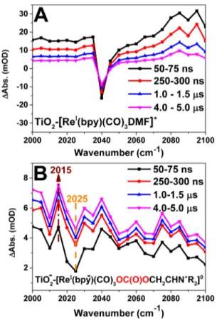
The reactions were followed on a longer time scale using a ns-laser/TRIR setup.Figure 2 compares the TRIR spectra of TiO2−[ReI(bpy)(CO)
3DMF]+ without (2A) and with (2B) TEOA and CO2. Atfirst sight, inFigure 2A, we can recognize the GSB peak and the oxidized catalyst peak TiO2(e−)− [ReII(bpy)(CO)
3DMF]2+ on the higher wavenumber side, which agrees well with the fs-FTIR results ofFigure 1A. These signals decay on a time scale of a few μs. In contrast, after introducing TEOA and CO2, we found that, in addition to the GSB of TiO2(e−)−[ReI(bpy)(CO)
3-OC(O)O-(CH2)2NR2]0 30 at 2020 cm−1, an absorption peak appears on the lower wavenumber side, and this grows stronger during thefirst few 100s of ns. This means an increased electron density on the Re center and can be attributed to a singly reduced catalyst.34,35 Our assignment is based on the following spectral analysis. We subtract the spectrum at 50 ns from the spectrum at 5000 ns for the TiO2-catalyst samples with and without TEOA/CO2 (Figure S3F). The resulting peak at 2015 cm−1for the sample with TEOA/CO2 is in good agreement with the results of Kubiak and co-workers,34who reported the FTIR spectrum of the singly reduced species [(tbu2-bpy)(CO)3ReCl]− (tbu2-bpy =4,4′-di-tert-butyl-2,2′-bipyridine), where the added electron density centered mostly on the bipyridine ligand.34 The electron density on the Re center induced by the anionic Cl− ligand in their work is matched by the carbonate ligand in the present case. The doubly oxidized TEOA (R2-N-(CH2)2OH) is formed via deprotonation and rearrangement to the corre-sponding R2N+ = CH−CH2OC(O)O− species. Thus, we propose the structural notation TiO2(e−)−[ReI(bpy−)(CO)
3 -OC(O)O-CH2CHN+R2]0for the reduced catalyst species from which one proton has been released. Note that the formation of the singly reduced catalyst is not at the expense of the electrons in the TiO2CB as the entire background absorption increases on the same time scale (Figure 2B). The only other plausible electron source for catalyst reduction is the oxidized TEOA Figure 1. (A) fs-TRIR for the ZrO2−[ReI(bpy)(CO)3]+ system in
DMF, (B) fs-TRIR for the TiO2−[ReI(bpy)(CO)3]+system without
TEOA, and (C) fs-TRIR for the TiO2−[ReI(bpy)(CO)3
-OC(O)O-(CH2)2N+R2]+ system in DMF/TEOA solution (5:1) and CO2
bubbling (the absorption at 2100 cm−1 was subtracted from the spectra to emphasize molecular signals).
radical [OC(O)O(CH2)2NR2]•+ that is unstable and highly reducing, such that each TEOA can donate two equivalents of electrons.36−39 On ZrO2 instead, there was no measurable formation of the singly reduced catalyst on this time scale (Figure S3F). This finding confirms that electron injection from [ReI(bpy)(CO)3-OC(O)O-(CH2)2NR2]+into TiO2plays a role in the photoreduction process. This triggers the first oxidation of TEOA on a ps time scale and releases a second equivalent of electrons on a time scale of ∼1 μs. The second equivalent mostly reduces the Re catalyst but some apparently ends up as CB electron. This can possibly be explained by the close proximity of the re-coordinated TEOA to TiO2 or by prior decoordination of the TEOA radical from the Re complex. Thermodynamically, the TEOA radical has enough reducing power to reduce the Re complex, and consequently, it is able to reduce the CB of TiO2.37 Figure 3A compares the traces at 2015 cm−1with and without introducing TEOA/CO2 corresponding to the transient spectra in Figure 2, which illustrates the differences in reactions on this time scale.
In the absence of TEOA/CO2, most of the signal from CB electrons in TiO2decays within 10μs by charge recombination with the oxidized catalyst: TiO2(e−)−[ReII(bpy)(CO)3DMF]2+ → TiO2−[ReI(bpy)(CO)3DMF]+. In the sample with TEOA/ CO2instead, the electrons in the TiO2CB do not show any decay up to tens of ms (Figure 3A and B). From the transient spectra and traces, it is clear that the reduced catalyst [ReI(bpy−)(CO)
3-OC(O)O-CH2CHN+R2]0 forms on a rapid time scaleτ1= 35 ns followed by a slow rise inFigure 3A (τ2=
1.8 μs). At the same time the background signal of CB electrons increases for which the IR extinction coefficient is larger than for the catalyst species (see the relativeΔAbs of the molecular peak vs broad background inFigure 2B).
TiO2 Role in CO2 Photoreduction by [ReI(bpy)(CO)3]+ Catalyst. The data indicate that there is an electron injection from the excited [ReI(bpy)(CO)3L]* to the TiO2CB on a ps time scale. For the sample with TEOA/CO2, this leads to phototriggered oxidation of TEOA and formation of a reduced catalyst, which is not seen on ZrO2. Therefore, TiO2 has an active role in the light-induced electron transfer reactions of this system. To further investigate the role of TiO2, we probed the destiny of CB electrons on longer time scales.
Figure 3B compares the traces at 2100 cm−1(CB electron absorption region) up to 1.5 s after photoexcitation of the TiO2 catalyst without (red trace) and with introducing TEOA/CO2 (black trace). Without TEOA/CO2, no electrons were left in the TiO2CB on this time scale, but introduction of TEOA and CO2 to the attached catalyst changed the kinetics drastically. Clearly, the electrons were still in the TiO2CB on this time scale, and only around 50% of the electrons had disappeared from the CB after around 100 ms, whereas the remaining 50% decayed withτ ≈ 1 s. This time scale (τ ≈ 1 s) is very similar to that reported for decay of the reduced catalyst signal (τ = 0.4 s) at 500 nm (bpy−ReIsignal)21even though we could not follow the molecular signal by mid-IR on the ms to seconds time scale. It is important to note that there is no accumulation of more reduced catalyst species upon repeated laser flashing or continuous irradiation. Thus, we propose that the CB electrons Figure 2. ns-TRIR spectra at different time delays after the
photoexcitation for (A) TiO2−[ReI(bpy)(CO)3DMF]+ and (B)
TiO2−[ReI(bpy)(CO)3] in the presence of TEOA/CO2. The
molecular GSB is at 2040 and 2025 cm−1, respectively, in agreement with the FTIR spectra. In (B) is also marked the peak at 2015 cm−1for the singly reduced catalyst TiO2(e−)−[ReI(bpy−)(CO)3
-OC(O)O-CH2CHN+R2]0.
Figure 3.(A) Traces at 2015 cm−1 for TiO2 catalyst (red) and for
TiO2calayst in the presence of TEOA and CO2(black) up to 10μs
(inset: showing the rising component) and (B) traces at 2100 cm−1 (electrons in TiO2CB) for TiO2catalyst (red) and TiO2 catalyst in
the presence of TEOA/CO2 (black) up to 1.5 s delay after the
photoexcitation.
are added to the reduced catalyst and lead to catalytic turnover, restoring the sample to the initial TiO2−[ ReI(bpy)(CO)3 -OC(O)O-(CH2)2NR2]0state; we discuss a possible mechanism in the next section. At present, we do not know if the CB electrons that decay withτ ≈ 89 ms also contribute to catalyst reduction or if they are lost in side reactions. In any case, these experiments add more evidence that TiO2plays a role in the photocatalytic reduction of CO2in this system other than being a scaffold. In this context, we note again that formation of the singly reduced catalyst [ReI(bpy−)(CO)3 -OC(O)O-(CH2)2N•+R2]0 on ZrO2, by quenching of the excited Re complex by the appended TEOA was not measurable (Figure S3F), which means that the electron injection process in TiO2 promotes formation of this species. This agrees well with the differences in catalytic activity of the catalyst on TiO2and on ZrO2.21
Proposed Photocatalytic Mechanism. The mechanism of CO2reduction by [ReI(bpy)(CO)3L] catalysts is still under debate with different mechanistic pathways being dis-cussed.8,35,40,41 Under electrocatalytic reduction conditions, the complex typically undergoes a two-electron reduction and loses the labile ligand (L) to form a [Re(bpy)(CO)3]−species that binds to CO2 and enters the catalytic cycle.41However, under photocatalytic reduction conditions, the one-electron-reduced complex [Re0(bpy)(CO)
3] may already bind to CO2 and start the catalytic cycle.42 Attaching the catalyst to TiO2 improves the catalytic activity but also further increases the mechanistic complexity. Scheme 2 presents our proposed mechanism of the photocatalytic reduction of CO2 using the TiO2−[ReI(bpy)(CO)3DMF]+ system in the presence of
TEOA/CO2 in DMF solution. As shown above, TiO2−
[ReI(bpy)(CO)
3]+ is able to capture CO2 and bind it as a carbonated TEOA ligand, forming the catalyst TiO2− [ReI(bpy)(CO)
3-OC(O)O-(CH2)2NR2]0. Upon photoexcita-tion of this complex, electron injecphotoexcita-tion into the CB of TiO2 occurs on the ps time scale. This is rapidly followed by electron transfer from the bound TEOA ligand [-(CH2)2NR2] to the oxidized catalyst to form TiO2(e−)−[ReI(bpy)(CO)
3 -OC(O)-O-(CH2)2N+R2]+. On a ns-μs time scale, the (-(CH2)2NR2)•+ radical cation shifts the radical from the nitrogen to an adjacent carbon that deprotonates and donates a second electron to further reduce the complex and form TiO2(e−)−[ReI(bpy− )-(CO)3-OC(O)O-CH2CHN+R
2]0+ H+. This must be followed by release of the oxidized TEOA to form the CO2-bound catalyst TiO2(e−)−[ReII(bpy)(CO)3CO2]0, where the CO2 carbon now coordinates to the Re center and two reducing equivalents are located on the CO2group. The CO2 may be derived from the carbonate-TEOA ligand that loses TEOA and rearranges to carbon coordination. Alternatively, the entire ligand decoordinates to form the one-electron-reduced, 17-electron species TiO2(e−)−[ReI(bpy−)(CO)3]0that then binds another CO2 molecule. Both pathways end up forming the critical TiO2(e−)−[ReII(bpy)(CO)3CO2]0 species. On a time scale of ms to seconds, electrons in the CB of TiO2 reduce [ReII(bpy)(CO)
3CO2]0 to form the metallocarboxylate inter-mediate species TiO2−[ReI(bpy)(CO)3CO2]−. The metal-locarboxylate intermediate can undergo a protonation (from TEOA/DMF) followed by loss of H2O to generate TiO2− [ReI(bpy)(CO)3CO]+.
42
This 18-electron species must be reduced before CO is released and the starting complex is regenerated. The question is where does this final electron come from under our experimental conditions. On the basis of results from Kubiak and co-workers,35we suggest that a small
fraction of electron equivalents from the TiO2 CB could catalytically reduce the entire population of [ReI (bpy)-(CO)3CO]+.
Kubiak and co-workers found that substoichiometric amounts (∼0.1 equiv) of reductant were sufficient to convert an entire sample of [ReI(bpy)(CO)3CO]+ to [ReI (bpy)-(CO)3DMF]+ in homogeneous solution. They presented a mechanism with an electron-transfer-catalyzed ligand ex-change.35 Formation of TiO2−[ReI(bpy−)(CO)
3CO]0 in a small amount leads to replacement of CO with solvent molecule (DMF) to form TiO2−[ReI(bpy−)(CO)3DMF]0. This complex is more reducing than the CO complex and therefore undergoes electron transfer with TiO2−[ReI (bpy)-(CO)3CO]+ to propagate the reduction-ligand exchange process according to the small loop presented inScheme 2.35 Finally, TiO2−[ReI(bpy)(CO)3DMF]+ binds TEOA and CO2 to reform the starting material as it was before laser flash initiation. Note that the scheme does not indicate all possible charge recombination steps and other loss pathways, which presumably make the overall quantum yield much less than 100%. The most interesting part of the proposed mechanism is that the catalyst is able to inject electrons to TiO2, and when the catalyst becomes reduced by TEOA, it can accept the electron back. This explains the redox active role of TiO2as an electron reservoir in the TiO2catalyst system in the presence of TEOA and CO2.
Scheme 2. Proposed Photocatalytic Mechanism of the [ReI(bpy)(CO)3]+Catalyst Attached to the TiO2Surface for CO2Reductiona
aThe states formed on the ps-μs time scale were spectroscopically observed (above the dashed line), whereas the remaining species (below the dashed line) are suggested based on published mechanisms to complete catalytic turnover (see text). For simplicity of notation, we ignore the (CO)3 groups in the catalyst chemical structure in this
■
CONCLUSIONSWe have shown that TiO2plays an important and active role in the photocatalytic reduction of CO2by the [ReI(bpy)(CO)
3L]+ catalyst in DMF and TEOA. First, the electron injection from the excited catalyst to TiO2is followed by rapid and efficient regeneration of the ReIcenter by the attached TEOA ligand. A second electron transfer, from the TEOA radical cation, leads to formation of the singly reduced [ReI(bpy−)(CO)3L] species on a time scale of 35 ns. We propose that the increase in photocatalytic activity observed when the catalyst is bound to TiO2, as compared to ZrO2or in homogeneous solution,21is due to the slow charge recombination and high oxidative power of the ReII species after injection as compared to the excited MLCT state on ZrO2or in solution, which results in a more efficient reaction with TEOA. Second, it seems that TiO2works as an electron bank that is able to accept, save, and give back the electrons to the catalyst and thus to help complete the photochemical reduction of CO2.
■
ASSOCIATED CONTENT*
S Supporting InformationThe Supporting Information is available free of charge on the
ACS Publications websiteat DOI:10.1021/jacs.6b11308. Steady-state absorption, emission, IR spectroscopy, and complementray time-resolved IR spectroscopic data (PDF)
■
AUTHOR INFORMATION Corresponding Authors *Mohamed.Qenawy@kemi.uu.se *Leif.Hammarstrom@kemi.uu.se ORCID Erwin Reisner:0000-0002-7781-1616 Leif Hammarström:0000-0002-9933-9084 NotesThe authors declare no competingfinancial interest.
■
ACKNOWLEDGMENTSThe authors are grateful for funding from the Knut and Alice Wallenberg Foundation, the Swedish Energy Agency, the Swedish Research Council, the Austrian Christian Doppler Research Association (Austrian Federal Ministry of Science, Research and Economy and the National Foundation for Research, Technology and Development), and the OMV Group. Dr. Mohammad Mirmohades, Jens Föhlinger, and Luca D’Amario are acknowledged for their help with fs-TRIR and ns-FTIR. Prof. Sascha Ott is also acknowledged for his helpful discussion. We are dedicating this work to the soul of Prof. Ahmed Zewail.
■
REFERENCES(1) Field, C. B., Barros, V. R., Dokken, D. J., Mach, K. J., Mastrandrea, M. D., Bilir, T. E., Chatterjee, M., Ebi, K. L., Estrada, Y. O., Genova, R. C., Girma, B., Kissel, E. S., Levy, A. N., MacCracken, S., Mastrandrea, P. R., White, L. L., Eds.; Climate Change 2014: Impacts, Adaptation, and Vulnerability. Part A: Global and Sectoral Aspects. Contribution of Working Group II to the Fifth Assessment Report of the Intergovernmental Panel on Climate Change; Cambridge University Press: Cambridge, United Kingdom and New York, NY, USA, 2014. (2) Riplinger, C.; Sampson, M. D.; Ritzmann, A. M.; Kubiak, C. P.; Carter, E. A. J. Am. Chem. Soc. 2014, 136, 16285.
(3) Roldan, A.; Hollingsworth, N.; Roffey, A.; Islam, H. U.; Goodall, J. B. M.; Catlow, C. R. A.; Darr, J. A.; Bras, W.; Sankar, G.; Holt, K. B.; Hogarth, G.; de Leeuw, N. H. Chem. Commun. 2015, 51, 7501.
(4) Takeda, H.; Koizumi, H.; Okamoto, K.; Ishitani, O. Chem. Commun. 2014, 50, 1491.
(5) Won, D.-I.; Lee, J.-S.; Ji, J.-M.; Jung, W.-J.; Son, H.-J.; Pac, C.; Kang, S. O. J. Am. Chem. Soc. 2015, 137, 13679.
(6) Appel, A. M.; Bercaw, J. E.; Bocarsly, A. B.; Dobbek, H.; DuBois, D. L.; Dupuis, M.; Ferry, J. G.; Fujita, E.; Hille, R.; Kenis, P. J. A.; Kerfeld, C. A.; Morris, R. H.; Peden, C. H. F.; Portis, A. R.; Ragsdale, S. W.; Rauchfuss, T. B.; Reek, J. N. H.; Seefeldt, L. C.; Thauer, R. K.; Waldrop, G. L. Chem. Rev. 2013, 113, 6621.
(7) Sahara, G.; Ishitani, O. Inorg. Chem. 2015, 54, 5096.
(8) Morris, A. J.; Meyer, G. J.; Fujita, E. Acc. Chem. Res. 2009, 42, 1983.
(9) Windle, C. D.; Campian, M. V.; Duhme-Klair, A.-K.; Gibson, E. A.; Perutz, R. N.; Schneider, J. Chem. Commun. 2012, 48, 8189.
(10) Windle, C. D.; Perutz, R. N. Coord. Chem. Rev. 2012, 256, 2562. (11) Figueiredo, M. C.; Ledezma-Yanez, I.; Koper, M. T. M. ACS Catal. 2016, 6, 2382.
(12) Li, C. W.; Kanan, M. W. J. Am. Chem. Soc. 2012, 134, 7231. (13) White, J. L.; Baruch, M. F.; Pander Iii, J. E.; Hu, Y.; Fortmeyer, I. C.; Park, J. E.; Zhang, T.; Liao, K.; Gu, J.; Yan, Y.; Shaw, T. W.; Abelev, E.; Bocarsly, A. B. Chem. Rev. 2015, 115, 12888.
(14) Woolerton, T. W.; Sheard, S.; Reisner, E.; Pierce, E.; Ragsdale, S. W.; Armstrong, F. A. J. Am. Chem. Soc. 2010, 132, 2132.
(15) Woolerton, T. W.; Sheard, S.; Pierce, E.; Ragsdale, S. W.; Armstrong, F. A. Energy Environ. Sci. 2011, 4, 2393.
(16) Manbeck, G. F.; Muckerman, J. T.; Szalda, D. J.; Himeda, Y.; Fujita, E. J. Phys. Chem. B 2015, 119, 7457.
(17) Agarwal, J.; Fujita, E.; Schaefer, H. F.; Muckerman, J. T. J. Am. Chem. Soc. 2012, 134, 5180.
(18) Kumar, B.; Llorente, M.; Froehlich, J.; Dang, T.; Sathrum, A.; Kubiak, C. P. Annu. Rev. Phys. Chem. 2012, 63, 541.
(19) Pastor, E.; Pesci, F. M.; Reynal, A.; Handoko, A. D.; Guo, M.; An, X.; Cowan, A. J.; Klug, D. R.; Durrant, J. R.; Tang, J. Phys. Chem. Chem. Phys. 2014, 16, 5922.
(20) Hawecker, J.; Lehn, J.-M.; Ziessel, R. J. Chem. Soc., Chem. Commun. 1983, 536.
(21) Windle, C. D.; Pastor, E.; Reynal, A.; Whitwood, A. C.; Vaynzof, Y.; Durrant, J. R.; Perutz, R. N.; Reisner, E. Chem. - Eur. J. 2015, 21, 3746.
(22) She, C.; Guo, J.; Lian, T. J. Phys. Chem. B 2007, 111, 6903. (23) Nahhas, A. E.; Cannizzo, A.; Mourik, F. v.; Blanco-Rodríguez, A. M.; Záliš, S.; Vlček, J. A.; Chergui, M. J. Phys. Chem. A 2010, 114, 6361.
(24) El Nahhas, A.; Consani, C.; Blanco-Rodríguez, A. M.; Lancaster, K. M.; Braem, O.; Cannizzo, A.; Towrie, M.; Clark, I. P.; Záliš, S.; Chergui, M.; Vlček, A. Inorg. Chem. 2011, 50, 2932.
(25) Asbury, J. B.; Hao, E.; Wang, Y.; Lian, T. J. Phys. Chem. B 2000, 104, 11957.
(26) Antila, L. J.; Santomauro, F. G.; Hammarstrom, L.; Fernandes, D. L. A.; Sa, J. Chem. Commun. 2015, 51, 10914.
(27) Mirmohades, M.; Pullen, S.; Stein, M.; Maji, S.; Ott, S.; Hammarström, L.; Lomoth, R. J. Am. Chem. Soc. 2014, 136, 17366.
(28) Mirmohades, M.; Adamska-Venkatesh, A.; Sommer, C.; Reijerse, E.; Lomoth, R.; Lubitz, W.; Hammarström, L. J. Phys. Chem. Lett. 2016, 7, 3290.
(29) Kirgan, R. A.; Sullivan, B. P.; Rillema, D. P. In Photochemistry and Photophysics of Coordination Compounds II; Balzani, V., Campagna, S., Eds.; Springer Berlin Heidelberg: Berlin, Heidelberg, 2007; p 45.
(30) Morimoto, T.; Nakajima, T.; Sawa, S.; Nakanishi, R.; Imori, D.; Ishitani, O. J. Am. Chem. Soc. 2013, 135, 16825.
(31) Wang, Y.; Asbury, J. B.; Lian, T. J. Phys. Chem. A 2000, 104, 4291.
(32) Anderson, N. A.; Lian, T. Coord. Chem. Rev. 2004, 248, 1231. (33) Anderson, N. A.; Ai, X.; Lian, T. J. Phys. Chem. B 2003, 107, 14414.
(34) Smieja, J. M.; Kubiak, C. P. Inorg. Chem. 2010, 49, 9283.
(35) Grice, K. A.; Gu, N. X.; Sampson, M. D.; Kubiak, C. P. Dalton Trans. 2013, 42, 8498.
(36) Reithmeier, R.; Bruckmeier, C.; Rieger, B. Catalysts 2012, 2, 544.
(37) Takeda, H.; Koike, K.; Inoue, H.; Ishitani, O. J. Am. Chem. Soc. 2008, 130, 2023.
(38) Amouyal, E. Sol. Energy Mater. Sol. Cells 1995, 38, 249. (39) Lehn, J. M.; Sauvage, J.; Gauthier-Villars: Paris, France, 1977; Vol. 1, p 449.
(40) Kou, Y.; Nabetani, Y.; Masui, D.; Shimada, T.; Takagi, S.; Tachibana, H.; Inoue, H. J. Am. Chem. Soc. 2014, 136, 6021.
(41) Sampson, M. D.; Froehlich, J. D.; Smieja, J. M.; Benson, E. E.; Sharp, I. D.; Kubiak, C. P. Energy Environ. Sci. 2013, 6, 3748.
(42) Schneider, T. W.; Ertem, M. Z.; Muckerman, J. T.; Angeles-Boza, A. M. ACS Catal. 2016, 6, 5473.