SSM’s external experts’ reviews of
SKB’s safety assessment SR-PSU
– engineered barriers, engineering
geology and chemical inventory
Initial review phase
SSM perspective
Background
The Swedish Radiation Safety Authority (SSM) received an application
for the expansion of SKB’s final repository for low and intermediate level
waste at Forsmark (SFR) on the 19 December 2014. SSM is tasked with
the review of the application and will issue a statement to the
govern-ment who will decide on the matter. An important part of the
applica-tion is SKB’s assessment of the long-term safety of the repository, which
is documented in the safety analysis named SR-PSU.
Present report compiles results from SSM’s external experts’ reviews of
SR-PSU. The general objective of these reviews has been to give support
to SSM’s assessment of the license application. More specifically, the
instructions to the external experts have been to make a broad
assess-ment of the quality of the application within the different disciplines
and to suggest needs for complementary information. The results may
also be helpful in guiding SSM to detailed review issues that should be
addressed in the assessment of the application.
Table of Contents
1) Bentonite in geological disposal of low and intermediate level
radio-active waste.
David G. Bennett and Göran Sällfors.
2) Preparatory review of the integrity of reinforced and non-reinforced
concrete structures in the extension of SFR.
Asadul H. Chowdhury and Biswajit Dasgupta.
3) Preparatory review of the rock engineering and engineering geology
issues related to the safety of the extension of SFR.
Ki-Bok Min and Ove Stephansson.
4) Review of the inventory of chemical substances in the waste and
waste packaging.
Liam Abrahamsen and Joe Small.
Project information
Contact person SSM: Georg Lindgren.
Contact persons and registration numbers for the different expert review
contributions are given in the report.
2016:12
SSM’s external experts’ reviews of
SKB’s safety assessment SR-PSU
– engineered barriers, engineering
geology and chemical inventory
This report concerns studies which have been conducted for the
Swedish Radiation Safety Authority, SSM. The conclusions and
view-points presented in the report are those of the author/authors and
do not necessarily coincide with those of the SSM.
Authors:
D.G. Bennett
1)and G. Sällfors
21)TerraSalus Limited, Oakham, United Kingdom 2)GeoForce AB, Billdal, Sweden
Bentonite in geological
disposal of low and
intermediate level radioactive
waste
Activity number: 3030014-1004 Registration number: SSM2015-1022 Contact person at SSM: Jinsong Liu
1
Authors:
D.G. Bennett
1)and G. Sällfors
21)TerraSalus Limited, Oakham, United Kingdom 2)GeoForce AB, Billdal, Sweden
Bentonite in geological
disposal of low and
intermediate level radioactive
waste
Activity number: 3030014-1004 Registration number: SSM2015-1022 Contact person at SSM: Jinsong Liu
Abstract
This report has been developed as part of the initial review phase of the extension of the SFR facility. It focuses on the properties of the bentonite components of the SFR facility and their contribution to the performance and safety of the repository. The objective has been to identify the usage of bentonite in different parts of the repository, and to preliminarily comment on the scientific soundness and overall quality of SKB’s reporting. Moreover the aim has been to review the evolution of geochemical and geomechanical properties of bentonite, as well as their impact on the long-term safety of the repository. Finally, potential bentonite-related issues that need to be addressed by SKB are proposed, as well as bentonite-related issues that are of importance and need to be focused on during the main review phase. Based on the reviews conducted during this initial review task, it appears that SKB has undertaken and documented a highly competent and systematic safety assessment for the SFR. SKB’s documentation safety assessment is generally well structured and well written, and it seems to cover the necessary areas. The documentation also appears to be generally transparent and traceable to underlying references, although this aspect has not been tested extensively during this review task. Assessing the scientific soundness of the many and various studies that underlie the safety assessment will need to be a part of the main review. SKB’s technical solutions for the disposal of the wastes are mature in the sense that SFR already exists and has been operating safely for a number of years. There is still a need though for SKB to demonstrate that the engineered barriers can be installed as designed under realistic conditions underground. SKB’s assessment methodology has been developing for over a decade and has been applied in several safety assessments for different waste types (e.g. spent fuel, low and intermediate level radioactive wastes). The
assessment methodology is regarded as appropriate, but SSM may wish to request further information to supplement the safety assessment.
Contents
1. Introduction ... 7
1.1. Background ... 7
1.1.1. The initial review phase ... 7
1.1.2. The main review phase ... 8
1.2. Scope and objectives ... 8
1.3. This report ... 8
2. SKB’s documentation ... 10
2.1. Structure ... 10
2.2. Content ... 10
3. Description of the SFR Disposal Facility ... 13
3.1. Overview of the SFR disposal facility ... 13
3.2. Uses and functions of bentonite barriers at SFR ... 15
3.2.1. The silo ... 15
3.2.2. The plugs and transition zones ... 16
3.2.3. The access tunnels ... 16
3.2.4. Sealing of boreholes ... 17
4. Bentonite processes and interactions ... 18
4.1. Bentonite processes ... 18
4.1.1. Hydraulic saturation ... 18
4.1.2. Swelling ... 18
4.1.3. Hydraulic conductivity ... 18
4.1.4. Piping and erosion ... 19
4.1.5. Freezing ... 19
4.2. Bentonite interactions ... 20
4.2.1. Interactions with swelling wastes ... 20
4.2.2. Interactions with cementitious materials ... 21
5. Safety assessment ... 23
5.1. Assessment methodology ... 23
5.2. Assessment endpoints... 23
5.3. Functions, initial state & evolution of bentonite-based barriers .. 24
5.3.1. Functions ... 24
5.3.2. Initial state ... 24
5.3.3. Evolution ... 24
5.4. Bentonite degradation scenario ... 25
5.5. Assessment results ... 26
5.6. Conclusions (safety, R&D & operational controls) ... 28
6. Conclusions... 29
6.1. Preliminary assessment of SKB’s documentation ... 29
6.2. Possible focus of reviews in the main phase ... 29
1. Introduction
1.1. Background
On 19 December 2014, the Swedish Radiation Safety Authority (SSM) received an application from Svensk Kärnbränslehantering AB (SKB) for the expansion of its repository at Forsmark for the disposal of low- and intermediate-level radioactive waste. The repository at Forsmark is known as the SFR. SSM is tasked with reviewing the application and will issue a statement to the Swedish government who will decide on the matter. An important part of the application is SKB’s assessment of the long-term safety of the repository, which is documented in the safety analysis named SR-PSU.
SSM’s review of the application has been divided into an initial review phase and a main review phase.
1.1.1. The initial review phase
The initial review phase has several objectives.
To develop a broad understanding of the application.
To determine whether SKB’s documentation is understandable and complete with regard to the information that is needed to be able to make a proper assessment of the application. SSM will ask SKB to provide complementary information on certain issues at the end of the initial review phase.
To identify key review topics for the main review phase. These are likely to be topics that have a significant impact on the assessment of whether the application fulfils relevant requirements. Furthermore, these will be topics on which it tends to be difficult to make judgments.
General instructions for the initial review of SKB’s documentation were as follows: Become familiar with SKB’s documentation and give a brief account of the
structure and most relevant parts of SKB’s documentation as well as the safety relevance of the topics under review. The SR-PSU main report is important since it puts various technical areas into the context of an overarching safety analysis. If necessary, higher order references should also be consulted, keeping in mind the general objective of the initial review phase.
Assess and briefly document the overall quality of SKB’s documentation. This should, if applicable, include a brief assessment of the structure, transparency, traceability, scientific soundness, as well as maturity of SKB’s technical solutions and of SKB’s methodology.
Identify any requests for complimentary information or clarifications that are deemed necessary to effectively assess the license application in depth. Suggest which are the most important review topics for the main review
phase and describe why these are judged to be important in view of the safety assessment results. For SSM the impact of different parts of the assessment to its overall results is an important question, because this in turn is connected to regulatory compliance.
If applicable, assess the adequacy of relevant models, data and safety functions as well as the handling of uncertainties. Merits and weaknesses of SKB’s work should be identified.
1.1.2. The main review phase
The main review phase will involve detailed analysis of specific issues. The specific review tasks for the main review phase will be defined using the results from the initial review phase. The main review phase is expected to involve a structured collaboration between external reviewers and SSM staff, so that multi-disciplinary issues can be handled in a more comprehensive manner than during the initial review phase. In the main review phase, SSM will determine if SKB’s application fulfils all necessary regulatory criteria.
1.2. Scope and objectives
This report has been developed as part of the initial review phase. It focuses on the properties of the bentonite components of the SFR and their contribution to the performance and safety of the repository.
The scope and objectives specified for the initial review assignment described in this report were:
To browse through the Main Report SR-PSU (SKB 2014a, TR-14-01) to account for the structure of topics in SKB’s reporting of the bentonite-related issues.
To review the Initial State Report (SKB 2014b, TR-14-02), and relevant references therein, to identify the usage of bentonite in different parts of the repository, and to preliminarily comment on the scientific soundness and overall quality of SKB’s reporting.
To review the Engineered Barrier Process Report (SKB 2014c, TR-14-04), and relevant references therein, focusing on Chapter 7, “Silo”, and
Chapter 10, “Plug” for the evolution of geochemical and geomechanical properties of bentonite, as well as their impact on the long-term safety of the repository, and to make preliminary comments on the scientific soundness and overall quality of SKB’s reporting.
To make an integrated review of the above mentioned reports and other relevant SKB documents, and suggest potential bentonite-related issues that need to be addressed by SKB, as well as bentonite-related issues that are of importance and need to be focused on during the main review phase.
1.3. This report
This report is structured as follows:
Section 2 provides an introduction to the design of the SFR and describes the uses of bentonite and bentonite-based materials and their main functions.
Section 3 identifies and briefly describes the structure of the SKB documentation reviewed and SKB’s approach to reporting on bentonite-related topics.
Section 4 addresses a range of geochemical and geomechanical topics related to the bentonite-based materials used to form barriers in the repository system.
Section 5 discusses various aspects of safety assessment focussing on the treatment of the bentonite barriers in the SR-PSU assessment.
Section 6 summarises preliminary conclusions from this initial review task, commenting on issues such as the overall quality of SKB’s documentation, the maturity of SKB’s technical solutions and assessment methodology, the adequacy of SKB’s assessments so far as can be ascertained at this stage, and topics that could/should sensibly be the focus of more detailed review during the main review phase.
2. SKB’s documentation
2.1. Structure
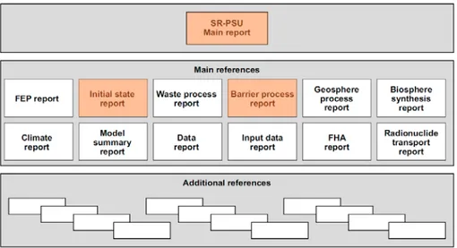
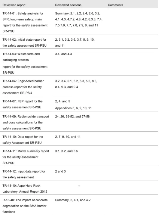
The structure of SKB’s documentation including the SR-PSU safety assessment is illustrated in Figure 1.1.
Figure 1.1 SKB’s documentation of the safety assessment for the SFR. The main reports reviewed in this initial review task are highlighted in orange.
2.2. Content
The Main Report for the SR-PSU safety assessment (SKB 2014a, TR-14-01) is an approximately 500 page long document that addresses the following topics:
Introductions, including a summary of SKB’s system for waste disposal, background on the SFR repository, a description of the wastes to be disposed of, a summary of the applicable regulations, and an introduction to safety assessment.
A detailed description of SKB’s safety assessment methodology, introducing the safety principles and regulatory requirements, setting out SKB’s ten step methodology and discussing its application over certain timescales and how uncertainties are addressed. Brief information is also given on quality assurance of the safety assessment.
SKB’s approach to the handling of FEPs (Feature, Events and Processes) and a description of how FEPs are addressed in the following areas; initial state FEPs, internal processes, external conditions.
A description of the initial state of the repository and its surroundings, including the wastes, the repository itself, the climate, ‘surface systems’ (such as topography, near-surface hydrology, ecosystems, human populations and water and land uses), the bedrock, hydrogeology and groundwater chemistry.
The ‘reference evolution’ envisaged for the repository (the climate and expected changes over the assessment period, including periods of temporate and periglacial conditions).
SKB’s approach to the selection of scenarios for the SR-PSU safety assessment, including a ‘main scenario’, less probable scenarios, residual scenarios and scenario combinations.
A description of the calculation cases undertaken in the SR-PSU safety assessment, including descriptions of the models and data used, and identifying the safety relevant radionuclides.
Within the main scenario different calculations are taken for: A global warming case.
An early periglacial case. Collective dose.
Calculations are undertaken for the following less probable scenarios: A high inventory case.
A high groundwater flow case.
An accelerated concrete degradation case. An accelerated bentonite degradation case. An earthquake case.
A case with high concentrations of complexing agents. A case with a water well downstream of the facility. A human intrusion case in which a well is drilled into the
facility.
Calculations are undertaken for the following ‘residual’ scenarios: No sorption in the repository.
No sorption in the bedrock. High water flow in the repository.
Alternative redox conditions in the repository. Extended global warming conditions.
Unclosed repository. Future human actions.
Glaciation and post-glacial conditions.
Safety assessment results in terms of calculated results for radionuclide transport and assessed doses.
A discussion of risk in terms of protection of human health and environmental protection.
Conclusions, including an assessment of the need for further research and further developments in terms of waste characterisation and facility design and operation.
The Initial State Report (SKB 2014b, TR-14-02), comprises some 120 pages. It was produced as a part of the second step in SKB’s ten-step assessment methodology (i.e. ‘description of initial state’) and it details the initial state of the repository at the time of its closure. The report also describes waste acceptance criteria, the reference waste inventory, the repository reference design, and control and inspection
processes that will be used to secure an appropriate initial state of SFR. Conclusions are drawn on the expected state of the repository and its environs immediately after closure for each of the eight repository vaults and for the repository plugs and closure components (see below). For example for the silo, one conclusion of the report is that ‘the bentonite wall filling is stable and only small movements have
been detected in the top filling, which indicates that the water absorption in the bentonite is insignificant’. An appendix to the report contains detailed information
The Engineered Barrier Process Report (SKB 2014c, TR-14-04), comprises some 340 pages. It was produced as a part of the fourth step in SKB’s ten-step assessment methodology (i.e. ‘description of internal processes’) and it documents available scientific knowledge on, and SKB’s handling of, processes that may occur in the repository engineered barriers. The processes considered were identified by SKB as being of relevance to the long term safety of the SFR based on the findings from a previous safety assessment. The Engineered Barrier Process Report (SKB 2014c, TR-14-04) describes the repository components and their safety functions, and then uses a defined template to discuss systematically each of the thermal, hydraulic, mechanical, chemical and radionuclide transport processes that might occur in each part of the SFR. The range of processes considered is not exhaustive, but is quite broad and appears to include the most important factors that are, or could be, relevant to safety. For example, for the silo the report discusses:
Thermal processes. Heat transport.
Phase changes/freezing. Hydraulic processes.
Water uptake and transport during unsaturated conditions. Water transport under saturated conditions.
Gas transport/dissolution. Piping/erosion.
Mechanical processes. Swelling.
Stress changes, effective as well as total stress changes. Deformation and settlement.
Failure and stability. Chemical processes.
Advection and dispersion. Diffusion.
Sorption.
Alteration of impurities. Colloid transport and filtering. Dissolution/precipitation. Concrete degradation.
Aqueous speciation and reactions. Osmosis.
Montmorillonite transformation. Iron–bentonite interaction. Montmorillonite colloid release. Microbial processes. Cementation in bentonite. Metal corrosion. Gas formation. Radionuclide transport. Speciation of radionuclides.
Transport of radionuclides in the water phase. Transport of radionuclides in the gas phase.
3. Description of the SFR Disposal Facility
3.1. Overview of the SFR disposal facility
Sections 1.2 and 4.3 of SKB 2014a (TR-14-01) describe the SFR broadly as follows. The SFR is designed as a subsea, hard-rock facility that is accessed via tunnels from an associated surface facility.
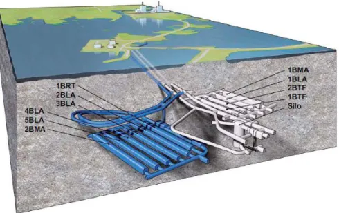
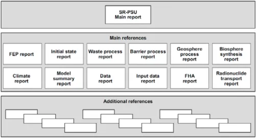
The existing part, ‘SFR 1’, comprises a silo and four waste vaults for different waste categories. The waste vaults are located about 60 m beneath the surface of the sea. The bottom of the silo is located deeper, however, at ~130 m beneath the sea surface.
The extension, ‘SFR 3’, would comprise six waste vaults. The waste vaults in the new part of the facility would be located ~120 m beneath the sea surface, which means that they will be close to the level of the bottom of the silo, see Figure 3.1.
Figure 3.1 The existing SFR 1 (light grey) and the extension SFR 3 (blue) with access tunnels. The waste vaults in the figure are the silo for intermediate-level waste, vault 1 and vault 2BMA for intermediate-level waste, vaults 1–2BTF for concrete tanks with intermediate-level waste with low activity levels, vaults 1BLA and 2–5BLA for low-level waste and the vault 1BRT for reactor pressure vessels.
Currently, there are two access tunnels. In order that whole reactor pressure vessels can be emplaced in the repository, a third access tunnel is planned.
The SFR facility will be decommissioned when all waste has been disposed of. When the decision on final shutdown has been taken, decommissioning of the facility will begin and will continue until the repository has been closed and sealed. A carefully designed decommissioning plan, centred on the closure sequence, will be drawn up in good time before the closure works begin. Demolition and
dismantling of existing systems will then be coordinated with the closure activities. After decommissioning and closure, the repository will be a passive system that can be left without further measures having to be taken to maintain its proper function.
Facilities above ground will be decontaminated and used for other purposes or demolished.
Closure will include installation of backfill material and plugs at selected locations in the underground facility. The primary purpose of these engineered barriers is to reduce the flow of water through the waste and impede human intrusion into the repository. Plugs are to be installed in access tunnels and connecting shafts, and all tunnels are to be backfilled with macadam. The upper part of the access tunnels is to be filled with stone blocks and sealed with concrete plugs. Finally, the ground surface will be restored so that it blends in with the surrounding landscape. In addition, all boreholes at SFR will be sealed so that the water flow in the surrounding rock is not affected by their presence.
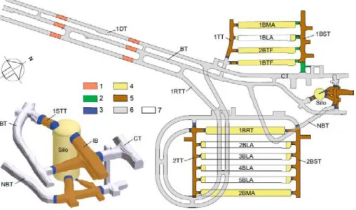
The closed repository is illustrated in Figure 3.2. The plug sections are hydraulically tight sections with bentonite that is held in place by mechanical constraints. Wherever warranted by the geometry of the tunnels and the properties of the rock, concrete plugs are installed as mechanical constraints. Where this is not suitable, a mechanical constraint consisting of backfill and transition material is installed instead. The backfill material consists of macadam and the transition material of 30/70 bentonite/crushed rock. The role of the transition material is to hinder bentonite transport out from the hydraulically tight sections, to take up the load from bentonite swelling and transfer it to the backfill material.
Figure 3.2 Schematic plan of SFR 1 and SFR 3, with a detailed view of the silo. Key to numbering: 1) Plugs in access tunnels 2) Transition material 3) Mechanical plug of concrete 4) Backfill material of macadam 5) Hydraulically tight section of bentonite 6) Backfill material in access tunnels and the central area of the tunnel system 7) Non-backfilled openings. Note that the figure shows Layout 2.0; Layout 1.5 is used in SR-PSU modelling.
3.2. Uses and functions of bentonite barriers at SFR
Bentonite blocks, bentonite pellets and mixtures of bentonite and sand, or bentonite and crushed bedrock material are used in a number of applications for the SFR repository. The main function of the bentonite-based components is to provide a hydraulic barrier and prevent or limit water flow through the repository, which could lead to migration of radionuclides. Another important property of the bentonite-based components is the development of a swelling pressure as the material
gradually becomes saturated. The swelling pressure is, in certain cases important as part of the mechanical stability of the system. The different applications of
bentonite or bentonite mixtures in the SFR are briefly described in the following paragraphs.
3.2.1. The silo
The silo is built in a huge cylindrical rock cavern, which is 35 m in diameter and 70 m high, and which is located between 65 m and ~130 m below the surface. The silo itself has a diameter of 25 m and is 50 m high. Bentonite or bentonite mixed with sand or crushed rock surrounds the silo at the bottom, along the periphery and at the top. The bentonite is from Milos in Greece, but has been converted from its original Ca-form to the Na-state by soda treatment.
Bentonite at the bottom of the silo
Above the base of the rock cavern, a 1.5 m thick layer of a sand/bentonite mixture is placed. The proportions of sand to bentonite are 90/10 and it is compacted in a number of layers, resulting in a very stiff foundation. The purpose of this sand/bentonite mixture is twofold, it shall act as a hydraulic barrier and it should also constitute a firm base for the foundation of the silo and allow very little settlement. SKB’s target value for the constraint modulus of the mixture was 100 to 150 MPa. Settlement during filling of the silo has been monitored (Pusch 2003) and
it seems that up until 2002 (the date of the last reported observations), the target value for the constraint modulus was reached with a good margin. However, no results from measurements made after 2002 have been found during this review. The bentonite/sand bottom bed should also have a hydraulic conductivity less than
1/
10 of the host rock, which is believed to be 10-8 m/s. Laboratory testing of
bentonite/sand mixtures with densities similar to the bottom bed revealed values on the order of 10-10 m/s, which are well below the required values.
The swelling pressure of the bottom bed has been estimated through laboratory tests and found to be on the order of 50 to 100 kPa, which means that it will have very little impact on the movement of the silo.
Bentonite around the periphery of the silo
The bedrock walls are covered with shotcrete, which also contains a system of drains. The space between the shotcrete and the silo is filled with bentonite pellets, which are not compacted. The purpose of the bentonite pellets is to act as a
hydraulic barrier and, in the longer term, to support the silo and the surrounding rock mass with a swelling pressure. The recommended minimum value of the hydraulic
conductivity here is also 1/
10 of that of the surrounding rock mass and, thus, it should
be less than 10-9 m/s. Testing of the bentonite at the densities expected has shown
that the hydraulic conductivity in all parts of the bentonite is expected to be equal to, or less than, 10-10 m/s.
Bentonite swelling pressures and densities have been measured a number of times since emplacement and are reported in Pusch (2003). The bentonite pellets are far from saturated, and so far the swelling pressures have been well below the maximum values of 500 kPa. The swelling pressures also appear to be far more uniform than assumed in the design. However, no results from measurements after 2002 have been found, either for the degree of saturation, or for swelling pressure.
Bentonite at the top of the silo
The silo is closed with a number of concrete lids on top of which 1.5 m of a sand/bentonite mixture will eventually be compacted. The purpose of this
bentonite/sand mixture is mainly to act as a hydraulic barrier, but it is also intended to support the frictional material filling the void above the silo. No information on the criteria for this sand/bentonite mixture material has been found.
3.2.2. The plugs and transition zones
With the exception of the silo, each of the different parts of the SFR, that is all the BLAs, both BMAs, both the BTFs and the BRT, are to be closed off by a concrete plug at one end and transition material, consisting of a 30/70 mixture of
bentonite/crushed rock, at the other end. The silo is closed off by a number of plugs incorporating a bentonite section between two concrete plugs.
The concrete plugs constitute a mechanical boundary for the vault, and the
bentonite/crushed rock constitutes a first hydraulic barrier and also, in some cases, a transition to the bentonite in the tunnels.
The transition zones are supposed to have a hydraulic conductivity of 10-9 m/s to
10-11 m/s, depending of the density of the mixture. These hydraulic conductivities
are based on laboratory test results, but the possibility of achieving these values in full scale testing is yet to be demonstrated.
The tight sections, which are constituted from bentonite blocks, have a target hydraulic conductivity value of 10-12 m/s to 10-13 m/s for an average emplaced dry
density of 1,400 kg/m3. It should be possible to achieve these hydraulic
conductivity values, but it needs to be demonstrated that the densities can be
achieved not only in a dry tunnel, but also if some water leaks in to the tunnel during operations. Another important question is how the Excavation Disturbed or
Damaged Zone (EDZ) is to be dealt with during plug design and construction, both conceptually and in practice.
3.2.3. The access tunnels
The access tunnels immediately outside the different repository tunnels are to be filled with bentonite. The bentonite will be emplaced in the form of compressed blocks, and the space between the blocks and the bedrock wall will be filled with bentonite pellets. These parts of the tunnels shall function as hydraulically tight
sections. In the access tunnels, between each part of the repository there will be one area where according to SKB the EDZ will ‘be removed’ in order to stop parallel flow of water in the EDZ. Again, more detail is needed on how this will be done in practice.
3.2.4. Sealing of boreholes
A number of boreholes intersect the repository area and these need to be sealed and closed off. SKB has suggested two different methods and both are supposed to function even for rather deep boreholes. Highly compacted bentonite is used where tight seals are needed and cement-stabilized plugs are cast where the boreholes pass through fracture zones. In our view there should not be any real difficulty in sealing intact boreholes, but there could be more problems for anomalous or ‘failed’ boreholes, and alternative methods might be needed.
4. Bentonite processes and interactions
This section discusses various processes that have been identified by the reviewers as being likely to be of the greatest relevance to the performance of the bentonite-based barriers in the SFR design and to the overall safety of the disposal facility. The processes discussed below include both physical/geomechanical processes and chemical/geochemical processes as these areas were defined as the main focuses of this initial review assignment. In detail, however, there are often couplings between different processes (e.g. between chemical and mechanical processes). The
selection of the processes discussed below has been made on the basis of the experience and expert judgement of the reviewers regarding which processes may be the most significant.
4.1. Bentonite processes
4.1.1. Hydraulic saturation
The time required to achieve full saturation of the different bentonite applications discussed in Section 3 will vary considerably, depending in particular on the percentage of bentonite in the material and on the hydraulic conductivity of the materials and the surrounding rocks. The saturation and evolution of several of these applications of bentonite-based materials in the SFR has not yet been modelled. SSM should consider requesting SKB to provide a more complete set of modelling analyses that examines the properties, behaviour and evolution of each of the bentonite-based barriers in the SFR in order to allow more meaningful reviews to be undertaken.
4.1.2. Swelling
The achievement of suitable bentonite swelling pressures is crucial, particularly for the proper functioning of the bentonite pellets surrounding the silo. The swelling pressure needs to be larger than 100 kPa, but not larger than 500 kPa. So far, as reported by Pusch (2003), no pressures outside the admissible pressure range have developed. Once the volume of bentonite pellets has been saturated, the swelling pressures should be rather uniform, as long as only limited piping and erosion have taken place. Full saturation should occur long before the concrete silo deteriorates and, thus, the structure of the whole design should remain intact. However, some 13 years have elapsed since the last swelling pressure measurements were reported and it is extremely important to ensure that the swelling pressures have not changed radically during this period. Thus, more recent monitoring data ought to be reviewed.
4.1.3. Hydraulic conductivity
As part of the repository design process, target values are given for the hydraulic conductivities of each of the different applications of bentonite-based materials in the SFR (e.g. the tight sections, the transition material, the filling around the silo, the
beds below and above the silo, the access tunnels and the borehole seals). The material densities specified do correspond to, and should provide, the desired hydraulic conductivities, but it remains to be shown that these densities can be obtained under practical working conditions.
4.1.4. Piping and erosion
During repository operations, including during waste emplacement, very little bentonite is in place (currently only the sand/bentonite mixture below the silo and the bentonite pellets surrounding the silo walls). The drains along the bedrock walls of the silo minimize the hydraulic gradients and should, therefore, limit the
likelihood of piping or erosion. For tunnels filled with bentonite blocks a substantial flow of water from the bedrock could be problematic. First, it might jeopardize the efficient placement of the bentonite blocks if they start to swell too early in the process. It might also cause unwanted flow of water eroding small particles of bentonite.
Many years after the repository is closed when all of the bentonite-based materials have become fully saturated, hydraulic gradients in and around the SFR will be very small. In this fully-saturated condition and with low hydraulic gradients there should not be any piping or physical erosion of bentonite.
Therefore, the critical phase during which piping and erosion of bentonite around the silo might occur is the transient period after the silo has been filled and closed off and the pumping has just been stopped. If the water flow from the bedrock is substantial, the drains will fill up rather quickly, and a large hydraulic gradient might develop across the compacted sand/bentonite foundation bed. As the bentonite content in the foundation bed is only 10%, it is prone to internal erosion and piping. The bentonite pellets could also be harmed by piping and erosion, and here also large hydraulic gradients might develop in the early phase after pumping is stopped. It will be important, therefore, to carefully manage the process of stopping the pumping and, thereby, control the gradual filling of the drainage system around the silo in order not to allow too large hydraulic gradients.
SSM should, therefore, consider making a more detailed review of the likely water inflows to the repository, and should also consider requesting further information from SKB on its plans for the cessation of pumping and managing the transition from operating conditions to long-term post-closure conditions.
4.1.5. Freezing
The consequences and potential problems related to freezing of bentonite at the SFR are addressed, for example in Emborg et al. (2007), SKB 2014c (2014-14-04) and SKB 2014f (R-14-29), and various scenarios are described in SKB 2014a
(TR-14-01, Section 5).
SKB (2014f, R-14-29) notes that:
The influence and extent of possible frost-heave in the silo has been quantified under the assumption that the material is frost susceptible and that no density redistribution occur as a consequence of freezing. The results suggest that no damaging pressures will develop in the silo due to ice-lens build up, but that the extent to which the silo bentonite will
self-heal after ice lenses thaw remains an open question. Page 380 of SKB 2014a (TR-14-01) indicates that, ‘A finite element calculation of the
self-healing (after an ice-lens formation) of a spherical void with the radius 0.5 m, which would represent severe damage to the bentonite caused by piping and erosion, has been done (Cronstrand 2014). Although the results cannot be used without reservations, they indicate that the bentonite would be fairly unaffected close to the concrete silo, which means that the sealing function would remain effective. This process should however be given further attention, since the self-sealing ability is crucial and both model capabilities and material data relevant to the silo bentonite are somewhat lacking.’ It has not been possible to review and evaluate the cited reference
(Cronstrand 2014) in any detail during this initial review task.
The redistribution of silo bentonite density as a consequence of freezing has been quantified based on the expected osmotic response and the assumption of having a frictionless system. This analysis shows that, instead of forming ice in the bentonite, it may be possible for substantial density redistribution to occur.
The effect of frost weathering (i.e. the effect of “trapping” unfrozen bentonite water within frozen surroundings, which then transforms into ice as temperature is lowered further) may give rise to possible pressure peaks. An estimation of maximum pressure has been made based on considering mechanical and chemical equilibrium between bentonite and ice, and assuming a simple elastic mechanical response. The results suggest that pressure peaks on the order of several tens of MPa cannot be ruled out. It is concluded that freezing of bentonite at SFR may result in several complex effects, including transient pressure increases, in redistribution of bentonite mass and, in the longer term, in increased hydraulic conductivities. This initial review has not been able to trace all of the detailed quantifications and arguments around these processes and it is suggested that bentonite freezing and its effects could form the subject of a more detailed review.
4.2. Bentonite interactions
4.2.1. Interactions with swelling wastes
The wastes to be disposed of at the SFR include various organic materials. Of these, bitumenized ion exchange resins, in particular, may undergo swelling. Bitumenized wastes are allocated to the silo and to the BMA and BLA vaults.
The Waste Process Report (SKB 2014e, TR-14-03) discusses various processes related to bitumenized wastes. Bitumen is a complex mixture of high molecular, polycyclic, aromatic hydrocarbons and can be produced in a range of qualities with different mechanical properties, ranging from low-viscosity, soft bitumens to hard plastic-elastic bitumens. Only soft bitumens are used for wastes emplaced in the SFR.
Bitumen is used to solidify ion-exchange resin wastes. These wastes contain variable amounts of evaporator salts. In the bitumenization process, waste is mixed into hot bitumen resulting in a bitumen matrix containing a dispersion of embedded waste particles. Although pure bitumen is hydrophobic, water can still be
transported into a bitumen matrix due to the presence of electrolytes. In pure bitumen the rate of water uptake is very low, since the driving forces are very small.
However, the bitumenized ion exchange resins and evaporator salts are hygroscopic, and the driving force for the diffusion of water into the bitumen matrix is much stronger.
In addition to chemical composition, the mechanical properties of bitumen are also affected by radiation, the production of gas within the waste matrix, and
temperature. Thus, the swelling behaviour can differ markedly between different types of bitumenized waste.
SKB 2014e (TR-14-03) notes that investigations of radioactive bitumen stored for 25 years under atmospheric, oxidising conditions showed significant aging to a depth of about 5 cm from the surface. The aged material was hard, very brittle and full of small fissures. The changes in the bitumen matrix had an indirect effect on the uptake of water and subsequent swelling. Experiments with bitumenized ion-exchange resins showed that irradiated resins had an order of magnitude faster water uptake than un-irradiated resins. However, because of the conditions under which these investigations were made, these findings are probably more relevant to the operational phase.
During the post-closure phase, when there is expected to be an absence of oxygen, the primary product of radiolytic decomposition will be hydrogen gas (i.e. hydrogen may make up ~95% of the gases produced) formed by cleavage of carbon-hydrogen bonds. SKB (2014e, TR-14-03) notes that CEA (2009) estimated a hydrogen yield of 1 × 10⁻³ to 1 × 10⁻² m3/drum/year. It can, however, be difficult to extrapolate with
confidence, between different types of bitumenized wastes, and the actual
proportions and amounts of gases that could form in the SFR will be dependent on the particular wastes emplaced and the prevailing conditions.
The production of hydrogen gas within the waste may cause swelling of the bitumen matrix. The degree of swelling will depend on several factors including, the properties of the bitumen, temperature, the waste loading, the homogeneity of the waste product, and the degree of containment and confinement provided by, and voidage present in, the surrounding materials and structures (e.g. the waste package).
In the bitumenization process, a void space is left in the waste package to make room for the additional volume. Nonetheless, SKB (2014e, TR-14-03) notes that swelling due to water uptake by bitumenized waste gives rise to mechanical stresses in the waste form and that excessive swelling may lead to mechanical stresses on the surrounding packaging and engineered barriers. For an analysis of such impacts the reader of the Waste Process Report is referred to Section 4.3.1 of that report, but, unfortunately no further information on the consequences of the swelling of bitumenized wastes are provided. The final section of SKB 2014e (TR-14-03) indicates that ‘knowledge of swelling pressure as a function of expansion volume is
used to evaluate how much pressure structures and barriers surrounding
bituminised waste will experience’, but how this is done is not apparent. There may,
thus, be a need to obtain more information and review in more detail the potential impact of swelling of the waste particularly on the ability of the bentonite pellets surrounding the silo to provide the appropriate swelling pressures and fulfil their hydromechanical functions.
4.2.2. Interactions with cementitious materials
The design of the SFR includes many interfaces between cementitious materials and bentonite-based materials (e.g. Figure 3.2). Various studies have highlighted
interactions that can occur at such interfaces and some have expressed concern that the mineralogical composition of the bentonite will not be stable under the hyper-alkaline pore fluid conditions (pH > 12) typical of cement and that the properties of the bentonite will degrade over long time periods (e.g. Savage et al. 2002; Gaucher and Blanc 2006).
Section 7.4.10 of the Engineered Barrier Process Report (SKB 2014c, TR-14-04) addresses the transformation of montmorillonite in the bentonite-based components as follows, ‘Under typical groundwater conditions, there are a range of possible
montmorillonite transformations that could lead to [the formation of] minerals with the same basic atomic structure as montmorillonite but decreased ability to swell. In the Silo of SFR, the bentonite is placed between concrete components, and relevant transformations of montmorillonite (and any accessory silicate minerals present) will be driven by contact with highly alkaline solutions. While it is clear that montmorillonite transformation is relevant in the presence of highly alkaline solutions, there is great uncertainty regarding reaction pathways and products as well as regarding extent or kinetics of the transformation reaction. To a significant part, this uncertainty results from the kinetic control of the process.’
SKB (2014a, TR-14-01) notes that ‘modelling performed by Cronstrand (2014)
indicates that as long as the concrete wall is fairly intact, the degradation proceeds slowly. Fractured concrete on the other hand, resulting in extensive exposure to fresh cement pore water, can have a significant corrosive effect on the
montmorillonite. The major uncertainties can be traced to the selected
thermodynamic database, the growth kinetics of newly formed phases and unknown factors that may reduce the swelling pressure and thereby allow local flow through the bentonite barrier. These areas will be studied further to add confidence to the assessment.’
SKB, thus, clearly recognises that various interactions and mineral transformations may occur at cement-bentonite interfaces, but also very much highlights the associated uncertainties. Although a scenario and set of calculation cases has been defined for ‘accelerated bentonite degradation’, it is not clear from the description of this scenario given in Section 7.6.4 of SKB 2014a (TR-14-01) that the scenario can be used to represent the effects of degradation at interfaces between the cementitious and bentonite-based components within the repository system. It is not clear at this stage, therefore, that the uncertainties associated with cement-bentonite interactions have been properly taken into account in the SR-PSU safety assessment. This is, therefore, a topic to which SSM may wish to return during the main review phase.
5. Safety assessment
This section discusses various aspects of the safety assessment relating to the objectives of this initial review task and the bentonite-based barriers at SFR. The discussion broadly follows the steps in SKB’s assessment methodology.
5.1. Assessment methodology
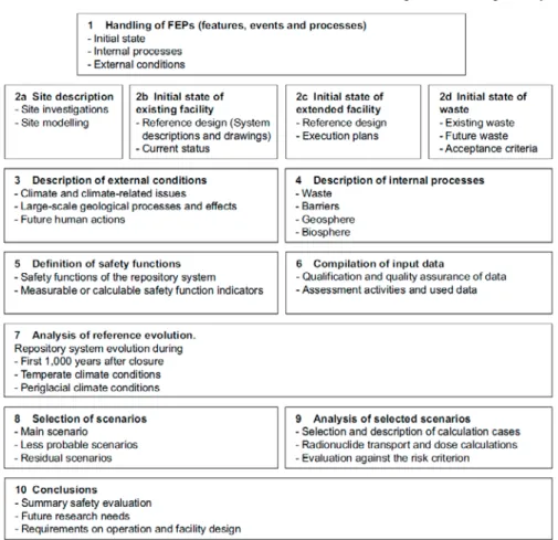
SKB has followed essentially the same assessment methodology for the SR-PSU assessment as it did for the assessment of spent fuel disposal in the SR-Site assessment (SKB 2010). The methodology involves ten steps (see Figure 2-4 of SKB 2014a, TR-14-01) including, (i) the handling of FEPs, (ii) description of the wastes, disposal facilities (existing and planned) and the site, (iii and iv)
consideration of internal and external processes, (v) the definition of safety functions, (vi) the compilation of data, (vii) analysis of the reference evolution for the site, (viii and xix) the selection and analysis of scenarios, and finally, (x) conclusions regarding safety, the need for R&D and the identification of requirements on facility design and operation.
The methodology is appropriate, but in our view provides relatively little
information on the justification of the design of the facility or its optimisation. For example, during this initial review we have not found much information that explains the reasons for the proposed designs of the bentonite-based barriers to be constructed for SFR 3 or that demonstrates that they will be mechanically stable. Similarly, few details are given on why particular engineered barrier materials (e.g. sand-bentonite mixes) have been chosen. It seems entirely reasonable to ask not only would the proposed design be safe (which is certainly addressed in the safety assessment), but also is the proposed design optimal in some sense (the ‘best’ that can be achieved without incurring unreasonable costs etc.)? Section 4 of SSMFS 2008:37 states that, ‘Optimisation must be performed and the best available
technique shall be taken into consideration in the disposal of spent nuclear fuel and nuclear waste.’ It may well be that SKB has further documentation that would help
to address such questions relating to design choices and optimisation, but we have not been able to find details on this topic during this initial review task.
5.2. Assessment endpoints
SKB’s safety assessment principally addresses and quantifies radiological doses and risks to humans. Exposures of non-human biota to radiation have also been
estimated (SKB 2014a, TR-14-01, page 367), but for an assessment of the risks from non-radiological toxic substances in the wastes (heavy metals such as cadmium, chromium, lead, or organics such as phenols, tributyl phosphate etc), the reader is referred to the Environmental Impact Assessment (EIA) (SKB 2014d), which is reported in Swedish. As the nature of an EIA is often somewhat different to that of a post-closure safety assessment, SSM may wish to review the consistency of the approaches taken for the assessments of the impacts of radionuclides and of non-radiological species.
5.3. Functions, initial state & evolution of
bentonite-based barriers
5.3.1. Functions
Aspects of the bentonite-based barriers considered in the safety assessment include the provision of mechanical stability, limiting advective transport, and promoting sorption (SKB 2014a, TR-14-01, Table 5-2). The safety function indicator
attributed to the bentonite-based materials of the silo and plugs is, however, defined in terms of providing low hydraulic conductivity, which contributes to the safety function ‘low flow in the waste vaults’ and the safety principle ‘retention of radionuclides’ (SKB 2014a, TR-14-01, Table 5-3).
In terms of the assumed/assessed importance to safety of the engineered barriers, it is notable that according to SKB, the bentonite components are only really considered important for the silo (SKB 2014a, TR-14-01, Table 11-1).
5.3.2. Initial state
As described above, the silo is made of in-situ cast concrete and is founded on a bed of sand and bentonite. The concrete silo is also surrounded by bentonite, which limits the flow of water through the wastes within it. The function of the flow barrier has been studied by Abarca et al. (2013). In the silo, the radioactive waste is deposited in a cylindrical concrete structure. Concrete walls divide the interior of the silo into disposal shafts. The waste in the silo is conditioned in cement, bitumen or concrete. The waste packages in the silo are continuously grouted during the operational phase. The entire concrete silo and its interior – including grout, concrete packaging and conditioned waste – serve as mechanical elements that resist the swelling pressure from water-saturated bentonite, the pressure from gas
formation and the load from self-weight. The silo top seal is designed to release gas in order to avoid gas driven advection. In conjunction with closure, the top part of the silo cupola will be backfilled with macadam to protect against rock fallout. The bottom bed of sand and bentonite has primarily a mechanical function. The pH-buffering function of the concrete and the grout keeps gas production due to microbial activity and iron corrosion low. The choice of concrete as an engineering material also ensures good sorption properties.
In order to restrict water flow through the waste vaults, the tunnel sections closest to the vaults will be sealed with sections of bentonite. These sections are supported by mechanical plugs.
5.3.3. Evolution
After closure, the engineered structures, including the barriers composed of
bentonite-based materials are assumed to slowly become hydraulically saturated. In the safety assessment, the saturation process is assumed to be instantaneous
following closure (SKB 2014a, TR-14-01, page 144). As noted above (Section 4.1.1) this is not a fully realistic assumption and the implications of slow re-saturation should perhaps be considered by more detailed modelling studies.
Page 151 of SKB 2014a (TR-14-01 ) indicates that during the first thousand years after closure water flows through the repository vaults increase by approximately two orders of magnitude on going from submerged conditions to on-shore
conditions. According to SKB, this is the most important process affecting the flow through the repository during this period. During the first thousand years after closure, degradation processes start to influence the hydraulic properties of concrete structures and materials in the repository (SKB 2014a, TR-14-01, section 6.3.8). SKB’s analyses suggest that the resulting effect on groundwater flow through the repository is small, however, compared with the increase in flow due to the retreating shoreline. The hydraulic properties of the bentonite barriers in the repository are assumed not to change during the first thousand years after closure (SKB 2014a, TR-14-01, page 151).
In the longer-term (i.e. more than 1,000 years after closure) SKB’s assessment assumes that the hydraulic conductivity of cementitious repository components increases until a ‘completely degraded’ state is reached when the concrete no longer provides a barrier to water flow. A similar approach has been taken for representing the effects of degradation of bentonite seals in tunnels at the ends of the vaults, and ‘complete’ degradation is estimated to lead to an order of magnitude increase in flow in the 1BMA and BTF vaults. In contrast, water flows through the silo are assumed to remain more or less constant because the silo is assumed to remain protected by its surrounding bentonite barrier (SKB 2014a, TR-14-01, section 6.4.5), which emphasises the importance attached to the bentonite barrier around the silo. This discussion suggests that SSM should consider a more thorough review of the modelling of flow through the engineered barriers as they progressively degrade, including a more detailed examination of the assumptions data and models (e.g. in Abarca et al. 2013) than has been possible in this initial review task.
SKB (2014a, TR-14-01, section 6.5.2) notes that during periods of periglacial conditions, it is possible for temperatures to be low enough for the entire repository to freeze. A ground temperature below 0°C at repository depth cannot be ruled out during the first possible occurrence of permafrost between 17,500 AD and 20,500 AD in the early periglacial climate case ground temperature of –3°C or less at repository depth cannot be ruled out during the occurrence of permafrost around 52,000 AD both in the early periglacial climate case and the global warming climate case. Under periglacial climate conditions, the most relevant scenarios for the SFR area predict significantly lower total flow through the waste vaults, longer path lengths and travel times, and higher flow-related transport resistance values compared with the values under temperate conditions. However, the results are dependent on the extent and number of taliks in the flow domain, and some of the waste vaults may experience small increases in total flows under periglacial relative to temperate conditions. The possible consequences of bentonite freezing have been briefly mentioned above in Section 4.1.5.
5.4. Bentonite degradation scenario
Section 7.6.4 of SKB 2014a (TR-14-01) describes a bentonite degradation scenario. The bentonite degradation scenario is based on an assumption that the safety function ‘low flow in waste vaults’ deviates from the main scenario due to
uncertainties in the consequences of extensive periglacial conditions in combination with uncertainties in the sealing properties of the bentonite. SKB assesses the probability of this scenario to be low, considerably less than 10%.
In the bentonite degradation scenario, the effects of the ice-lens formation are assumed to be so large that the bentonite surrounding the silo will have a
permanently increased hydraulic conductivity, which results in an increase in water flow. It is further assumed that ice-lens formation occurs during the first permafrost period in the early periglacial climate case (i.e. in the period from 17,500 to
20,500 AD).
SKB argues that the concrete will not freeze as the temperature needed for concrete to freeze is lower than the temperature needed for bentonite to freeze. SKB also argues that the size of the plugs implies that harmful ice-lens formation could not occur and hence treats the plugs in the same way as in the main scenario. No more detailed justifications for these assumptions have been seen however.
A calculation case was set up to evaluate the influence of an ice-lens on the flow in the silo (Abarca et al. 2013). In the model, the affected bentonite barrier was simulated by defining a ring of high permeability material, surrounding the silo concrete structure at mid-height. The results suggested an order of magnitude increase in flow in the degraded volume, whereas the flow increase in the rest of the silo was moderate. The silo concrete structure limited the amount of water that could penetrate the waste.
SKB argues that this scenario can also be seen as representative for other bentonite degradation processes, for example montmorillonite alteration due to interactions with cementitious materials. As noted above in Section 4.1.5, however, this latter argument in particular does not at first sight seem particularly sound and further review may be needed.
5.5. Assessment results
Section 9 of SKB 2014a (TR-14-01) summarises the many results from the safety assessment calculations. The results are presented in terms of assessed potential annual dose and the contributions of different radionuclides to peak dose are tabulated.
Results for the bentonite degradation scenario (peak potential annual dose of 5.9 μSv at 6,250 AD, dominated by releases from the silo and by Mo-93 and C-14) (SKB 2014a, TR-14-01, Table 9-6) are broadly similar to those for the global warming variant – having a slightly earlier and higher peak and a very slightly lower tail in the long-term.
Results for the residual high flow in the repository scenario, in which both the concrete and bentonite barriers of the repository were assumed to have degraded properties from the start of the assessment, are almost one order of magnitude higher than those for the global warming variant (peak potential annual dose of 46.9 μSv at 5,000 AD, dominated by releases from the silo and by Mo-93, C-14 and Ni-59) (SKB 2014a, TR-14-01, Table 9-13).
Tables 9-20 and 9-21 of SKB 2014a (TR-14-01) together provide a useful summary of the assessment results for all of the scenarios considered. These tables help to put the results for the bentonite degradation and engineered barrier related scenarios into a wider context. For example, they show that higher peak potential annual doses are calculated for several of the intrusion wells scenarios, although these scenarios are
attributed very low probabilities and, hence, lower risks (SKB 2014a, TR-14-01, Tables 10-1 and 10-2).
It is important to remember that although using safety assessment calculations to identify which radionuclides are key to dose and risk is a sensible practice, it can also be misleading if the many assumptions upon which that calculations are made are not taken properly into account. For example, SKB 2014a (TR-14-01, page 367) states, ‘The relative contributions of individual radionuclides to the total risk from
the repository depend on a number of factors, including the initial inventory of the radionuclides in the wastes, the capacity of the different waste vaults for retention and retardation of the different radionuclides, the behaviour of released
radionuclides in the geosphere and biosphere, and the radiotoxicity of the
radionuclides. In addition, the estimates of relative risk for individual radionuclides is influenced by the degree of pessimism inherent in the assumptions made in the assessment; i.e. assumptions used to model processes and values assigned to model parameters. Hence, a ranking of the radionuclides in terms of their contribution to the total risk will be conditioned by all above-mentioned factors, and should be seen as valid only for this specific assessment including its pessimisms, i.e. the results do not necessarily represent the ranking of the “actual” risks’. Therefore, drawing
conclusions as to which are the most important factors in a safety assessment is a complex task that cannot necessarily be made from safety assessment results alone and often requires expert judgement.
These caveats notwithstanding, SKB (2014a, TR-14-01, page 368) notes that different radionuclides contribute to the total risk at different times:
Based on activity and radiotoxicity, Ni-63 is one of the most important radionuclides. However, because of its short half-life, Ni-63 will decay to insignificant levels during the time when the repository is covered by the sea. The low hydraulic gradient under the sea, resulting in low
groundwater flow, means that significant amounts of Ni-63 cannot be transported to the biosphere.
Based on radiotoxicity, Am-241 is the most important radionuclide. However, Am-241 is highly immobile under undisturbed repository conditions, i.e. high pH and reducing conditions, which means that its contribution to the radiological risk is small. Since the half-life of Am-241 is relatively short, most of the inventory of Am-241 is expected to decay during the first 1,000 year period, the time at which it is assumed by SKB that the repository might first be disturbed by a drilling intrusion. On this basis SKB argues that the potential impact of Am-241 released from the repository via an intrusion well is limited.
During the first 20,000 years, the inventory of Mo-93 and C-14 decreases significantly due to decay. The flow-limiting function of the concrete material in BMA will be maintained for at least this period, and longer for the silo. Thereafter, the possible contribution to radiological risk from these radionuclides is insignificant due to their radioactive decay. After 50,000 years, freezing of the concrete barriers in the repository may
occur. Further, ice-sheet development cannot be excluded. At that time, the activity of radionuclides in the repository is completely dominated by the limited amount of long-lived radionuclides with a half-life so long that they will not decay substantially during the assessment period.
At the end of the assessment period (i.e. 100,000 years), the levels of all of the disposed radionuclides are close to, if not below, clearance levels. Given this discussion, it would appear that important assumptions include:
The period for which the repository is assumed to remain undisturbed (i.e. the 1,000 or 3,000 year period depending on the scenario in which there is assumed to be no human intrusion), and
The time after which the repository might suffer damage due to ice sheet development.
The probabilities assigned to the scenarios.
Even so, an important point to note is that according to SKB 2014a (TR-14-01, page 369), ‘The contribution from uranium progeny to the total risk is not projected
to increase significantly beyond 100,000 years’. Thus, although SKB cannot
exclude the possibility that permafrost may reach repository depth, or that future ice-sheet development may have a severe impact on the protective capability of the repository, limitation of the amount of long-lived radionuclides that are disposed of (i.e. Waste Acceptance Criteria) ensures that regulatory requirements for the protection of human health and environment are met even after such events. This limitation of the inventory of long-lived radionuclides is also used by SKB to justify the depth of the proposed repository extension (SKB 2014a, TR-14-01, page 369).
5.6. Conclusions (safety, R&D & operational controls)
The central conclusion of the SR-PSU safety assessment is that the extended SFR repository (SFR 1 and SFR 3) meets the regulatory criteria on long-term safety (SKB 2014a, TR-14-01, page 365). It has not been the purpose of this initial review to take a definitive view on this conclusion; that will be SSM’s task at a later stage of the review.
SKB is proposing to undertake various further R&D studies (SKB 2014a, TR-14-01, Section 9) and to define and implement operational controls, including Waste Acceptance Criteria (WAC). For example, SKB notes on page 380 of SKB 2014a (TR-14-01) that the assessment of swelling of waste in the silo is handled by “ensuring expansion volume when grouting the waste and by the method for closing
the repository”. Exactly how this is and will be done is unclear. SKB also proposes
to define WAC in order to control the potential effects of waste swelling in 1-2 BMA. It is suggested that SSM considers a more detailed review of the WAC and of the swelling of wastes, and the complex relationships between waste swelling, the assessed performance and safety of the disposal facility, and the possible need (or otherwise) for WAC in terms of operational procedures for waste conditioning and for closing of the silo. It is notable that, at the same time as proposing to manage the issue through the use of WAC, SKB is also planning to conduct further research studies to investigate the properties of waste forms containing ion-exchange resins and / or evaporator concentrates. It is suggested that SSM ought to keep abreast of such research.
6. Conclusions
6.1. Preliminary assessment of SKB’s documentation
Based on the reviews conducted during this initial review task, it appears that SKB has undertaken and documented a highly competent and systematic safety
assessment for the SFR. SKB’s documentation safety assessment is generally well structured and well written, and it seems to cover the necessary areas.
The documentation also appears to be generally transparent and traceable to underlying references, although this aspect has not been tested extensively during this review task. Assessing the scientific soundness of the many and various studies that underlie the safety assessment will need to be a part of the main review. SKB’s technical solutions for the disposal of the wastes are mature in the sense that SFR already exists and has been operating safely for a number of years. There is still a need though for SKB to demonstrate that the engineered barriers can be installed as designed under realistic conditions underground.
SKB’s assessment methodology has been developing for over a decade and has been applied in several safety assessments for different waste types (e.g. spent fuel, low and intermediate level radioactive wastes). The assessment methodology is regarded as appropriate, but SSM may wish to request further information to supplement the safety assessment (e.g. related to optimisation).
6.2. Possible focus of reviews in the main phase
Based on the reviews conducted during this initial review task, the following table summarises the suggestions that have been made regarding potential areas for more detailed review during the main review phase.
Potential review topic Significance
Detailed review of water flow through the repository, including:
Review of the assumptions, data and models used to simulate degradation of bentonite and cementitious engineered barriers and the effects of barrier degradation on flow.
Review of the representation in the safety assessment of localised effects on water flow of bentonite-cement interactions.
Review of how the plugs that are intended to seal the EDZ will function hydraulically when the bentonite deteriorates.
Calculated potential doses due to radionuclide transport via the groundwater pathway are, in general, directly related to the amounts of water flow.
Potential review topic Significance
The properties and behaviour (e.g. swelling) of bitumenized wastes in the silo and the potential hydromechanical effects of such swelling on the bentonite around the silo.
SKB’s assessment assumes that water flows through the silo remain more or less constant in the long term (after 1,000 years) because of the surrounding bentonite barrier. This is a key
assumption on which the safety assessment depends.
The effects of bentonite freezing, including transient pressure increases, redistribution of bentonite mass and increased hydraulic conductivities and water flows.
SKB’s assessment assumes that water flows through the silo remain more or less constant in the long term (after 1,000 years) because of the surrounding bentonite barrier. This is a key
assumption on which the safety assessment depends.
Detailed review of the potential for piping and erosion of bentonite-based barrier materials at low densities such as in the pellet filling around the silo.
SKB’s assessment assumes that water flows through the silo remain more or less constant in the long term (after 1,000 years) because of the surrounding bentonite barrier. This is a key
assumption on which the safety assessment depends.
Review of monitoring data on settlement, horizontal pressures and wetting of the bentonite surrounding the silo.
It is vital to see how well SKB’s predictions for these parameters agree with the actually observed performance of the silo bentonite.
Review of SKB’s justification for the proposed repository design and demonstration of optimisation.
Section 4 of SSMFS 2008:37 requires that ‘Optimisation must be performed
and the best available technique shall be taken into consideration in the disposal of spent nuclear fuel and nuclear waste.’
Detailed review of the assumptions, data and models used to simulate the chemistry (e.g. redox state, speciation, solubility, sorption, precipitation) and transport of Mo, C-14, Pu and U.
Calculated potential doses due to radionuclide transport via the groundwater pathway are, in general, directly related to the solubilities of the radionuclides in the water, as affected by retardation processes such as sorption. The radionuclides identified are the key contributors to calculated potential doses in the main scenario and the less