Research
Assessment of inertia effects on
transient clad-to-coolant heat
transfer and coolant flow under
2017:20
SSM:s perspektiv
Bakgrund
Beräkningsprogrammet SCANAIR har utvecklats av IRSN (Institut de Radioprotection et de Sûreté Nucléaire) för att analysera reaktivitet-shändelser (RIA) i lättvattenreaktorer. I utbyte mot årliga bidrag till utvecklingen av SCANAIR har SSM tillgång till beräkningsprogrammet och kan utföra egna analyser av bränslebeteende under reaktivitetshän-delser. Arbetet utförs av Quantum Technologies AB, vilka utvecklar och administrerar beräkningsprogrammet på SSM:s uppdrag.
SSM:s utveckling av SCANAIR är främst inriktad mot de termohydrauliska modellerna, i syfte att förbättra analysmöjligheterna i kokvatten reaktorer. I ett tidigare arbete har en modell för tvåfasströmning utvecklats vilken tagits in av IRSN i SCANAIR V_7_5. Föreliggande arbete är 2016 års bidrag till SCANAIR-utvecklingen och är en undersökning av om tröghets-effekter hos kylmedlet kan förklara de problem man ser vid modellering av värmeöverföring från kapsling till kylmedel vid en RIA i en kokvatten-reaktor. Undersökningen utgår från hydrodynamiska modeller med intentionen att förbättra modellen för tvåfasströmning.
Resultat
Detta projekt resulterade i att hypotesen om att tröghetseffekter påverkar värmeöverföring behövde förkastas. Dock har andra lärdomar dragits, bland annat att flödet av kylmedel påverkar mer och även påverkas av ångbildningen. Vidare noteras att modellen för tvåfasströmning som den är utformad idag är otillräcklig för att möjliggöra förbättringar som tar hänsyn till tröghetsfenomen på det axiella flödet.
Behov av ytterligare forskning
Fortsatt arbete med utveckling av analysmöjligheterna i SCANAIR plan-eras i samarbete med IRSN. Under 2017 planplan-eras att utveckla modellen för tvåfasströmning med en del som beskriver det axiella flödet.
Projektinformation
Kontaktperson SSM: Anna Alvestav Referens: SSM2015-3816 / 7030068-00
2017:20
Author: Lars Olof Jernkvist
Quantum Technologies AB, Uppsala Science Park, SE-75183 Uppsala
Assessment of inertia effects on
transient clad-to-coolant heat
transfer and coolant flow under
This report concerns a study which has been conducted for the Swedish Radiation Safety Authority, SSM. The conclusions and view-points presented in the report are those of the author/authors and do not necessarily coincide with those of the SSM.
Assessment of inertia effects on
transient clad-to-coolant heat
transfer and coolant flow under
reactivity initiated accidents
April 26, 2017.
Lars Olof Jernkvist
Quantum Technologies AB
Uppsala Science Park, SE-75183 Uppsala
Contents
Summary ... III Sammanfattning ... IV
1 Introduction ... 1
2 Clad-to-coolant heat transfer in RIA conditions ... 5
2.1 Fundamental concepts in boiling heat transfer ... 5
2.2 Experimental database ... 7 2.2.1 Ex-reactor tests ... 7 2.2.2 In-reactor tests ... 10 2.3 Modelling ... 15 2.3.1 General ... 15 2.3.2 SCANAIR ... 16
3 Assessment of coolant inertia effects ... 19
3.1 Annular vapour film formation ... 20
3.2 Bulk vapour generation and coolant axial flow ... 23
4 Conclusions and recommendations ... 27
Summary
In this report, simple hydrodynamic models are used for studying the effects of coolant inertia on fuel-to-coolant heat transfer and coolant flow under reactivity initiated accidents in light water reactors. The objective is to assess if the inertia effects are important enough to warrant modification of QT-COOL, a coolant channel module for two-phase flow that has recently been implemented as an optional model in the SCANAIR fuel rod analysis program.
The results of our study suggest that inertia has a negligible impact on the growth kinetics of the continuous vapour film that forms between the fuel rod cladding tube and the surrounding subcooled liquid water, when the fuel rod is rapidly heated. This vapour film has an insulating effect, and it has a significant impact on the fuel-to-coolant heat transfer. For conditions expected under reactivity initiated accidents in light water reactors, the growth of the vapour film seems to be rate controlled by transfer of heat and mass across the liquid-vapour interface rather than by inertia of the liquid that is displaced radially by the growing film.
On the other hand, our assessment indicates that the coolant inertia is important for the axial flow kinetics in the coolant channel when the accident conditions are such that net vapour generation occurs anywhere along the fuel rod. The reason is that the vapourization involves a large local volume expansion, which in turn entails accele-ration and displacement of a significant amount of water along the coolant channel. Coolant inertia effects are not accounted for in the current version of the QT-COOL coolant channel module, but suggestions are given for how the module can be improved to overcome this limitation. The report also contains a review of relevant experimental data that are deemed suitable for future calibration and validation of the QT-COOL module.
Sammanfattning
I föreliggande rapport används enkla hydrodynamiska modeller för att studera effekter av kylvattnets masströghet, dels på transient värmeöverföring från bränsle till kylvatten, dels på kylvattnets strömning, under reaktivitetsinducerade olyckor i lättvattenreaktorer. Målsättningen är att utvärdera om tröghetseffekterna är till-räckligt betydelsefulla för att motivera modifiering av QT-COOL, vilket är en beräkningsmodul för kylvattenkanalen som nyligen införts som en valbar modell för tvåfasströmning i bränslestavberäkningsprogrammet SCANAIR.
Resultaten av vår studie antyder att masströgheten har en försumbar inverkan på tillväxtförloppet hos den sammanhängande ångfilm som bildas mellan bränsle-stavens kapslingsrör och omgivande underkylt vatten, då bränslestaven hastigt uppvärms. Denna ångfilm har en isolerande funktion, och har en stor inverkan på värmeöverföringen från bränslet till kylvattnet. För förhållanden som kan förväntas under reaktivitetsinducerade olyckor i lättvattenreaktorer synes ångfilmens tillväxt-hastighet begränsas av mass- och värmetransport över gränsytan mellan vätska och ånga, snarare än av masströgheten hos det vatten som förflyttas radiellt av den växande ångfilmen.
Vår utvärdering visar å andra sidan att kylvattnets masströghet är av betydelse för den axiella flödeskinetiken i kylkanalen i det fall olycksscenariot leder till ång-bildning någonstans längs bränslestaven. Anledningen till detta är att ångång-bildningen medför en stor och lokal volymsexpansion, vilken i sin tur leder till acceleration och förflyttning av en betydande mängd vatten längs med kylkanalen.
Effekter betingade av kylvattnets masströghet beaktas ej i den nuvarande versionen av beräkningsmodulen QT-COOL, men förslag ges på hur modulen kan förbättras för att undanröja denna begränsning. Rapporten innehåller även en genomgång av relevanta experimentella data, som bedöms lämpade för framtida kalibrering och validering av beräkningsmodulen QT-COOL.
1 Introduction
A reactivity initiated accident (RIA) is a nuclear reactor accident that involves an unwanted increase in fission rate and reactor power. The immediate consequence of an RIA is a fast rise in fuel power and temperature. In light water reactors (LWRs), heat transfer from the fuel rod cladding tubes to the water coolant is essential for limiting the fuel rod temperature excursion during the accident. Of particular concern is the possible occurrence of a boiling crisis, i.e. a transition to a regime with film boiling and low heat transfer at the clad-to-coolant interface. If film boiling and the resulting high cladding temperature are maintained for a sufficient period of time, the fuel rod may fail through cladding ballooning and burst, or through cladding disruption by thermal shock upon quenching [1].
In-reactor and ex-reactor experiments suggest that clad-to-coolant heat transfer is much different during RIAs than under steady-state operating conditions or slow overpower transients, due to the rapid heating of the cladding: Heating rates up to several thousands kelvin per second are expected in some RIA scenarios that involve inadvertent ejection of control rods from the core [1]. Clad-to-coolant heat transfer models developed for steady-state operating conditions or slow reactor transients are therefore not suited for application to RIA, and computer programs intended for fuel rod thermal-mechanical analyses of RIAs use either specifically designed heat transfer models or significantly modified steady-state models. A recent benchmark of this kind of software, organized by the Working Group on Fuel Safety (WGFS) of the OECD Nuclear Energy Agency (NEA) Committee on the Safety of Nuclear Installations (CSNI), revealed that large differences and uncertainties exist among the applied clad-to-coolant heat transfer models, especially when a boiling crisis takes place [2, 3].
The SCANAIR computer program is intended for analyses of the thermal-mechanical behaviour of LWR fuel rods under reactivity initiated accidents. The program, which is used by the Swedish Radiation Safety Authority (SSM), is equipped with clad-to-coolant heat transfer models that are developed specifically for applications to RIA conditions [4]. The models cover coolant conditions of pressurized water reactors (PWRs) [5] as well as the specific coolant conditions of the Japanese Nuclear Safety Research Reactor (NSRR) [6]. The latter conditions are of particular interest, since fuel rod experiments under simulated RIA conditions in the NSRR, with stagnant water at room temperature and atmospheric pressure as coolant, answer to the major part of the current experimental database on fuel rod behaviour in RIA conditions [1].
Models for transient clad-to-coolant heat transfer under cooling conditions typical for boiling water reactors (BWRs) are, however, not available in SCANAIR. Organizations interested in applying SCANAIR for analyses of RIAs in BWRs are therefore extending the program with suitable models. For example, the VTT
Technical Research Centre of Finland has developed an interface between SCANAIR and their in-house thermal-hydraulic code GENFLO [7]. GENFLO is a general software that contains a five-equation thermal-hydraulics model for the two-phase (liquid and steam) water coolant. It solves the energy and mass conservation equations for the two phases individually, combined with a single momentum equation with drift-flux phase separation. This model is much more elaborate than the standard coolant model in SCANAIR, which is restricted to one-dimensional flow of single phase (liquid) water [4]. Hence, in contrast to the SCANAIR standard model, the GENFLO model lends itself to analyses of BWR cooling conditions, and VTT intends to model the coolant properties and the clad-to-coolant heat transfer by use of the models available in GENFLO [8].
A similar approach has been taken by Quantum Technologies in Sweden, who has implemented an optional coolant channel module in SCANAIR as an in-kind contribution to SCANAIR development under contract with SSM [9, 10]. This module, named QT-COOL, contains a simple two-equation homogeneous equilibrium (HE) model for the two-phase water coolant. More precisely, the liquid-steam mixture is treated as a homogeneous pseudo fluid that obeys the usual equations of a single phase fluid. The conservation equations for energy and mass are solved in one dimension (along the fuel rod), but not the momentum equation. This means that the coolant pressure must be given as input to the program. The QT-COOL module also contains a fairly large set of clad-to-coolant heat transfer correlations for a wide range of cooling conditions [9]. QT-COOL is available as an optional coolant channel module in SCANAIR from version V_7_5 and later. The QT-COOL module was originally developed for general thermo-mechanical analyses of LWR fuel rods under steady-state conditions and slow transients, and not specifically for modelling conditions under reactivity initiated accidents. For this reason, the module has been validated against RIA simulation tests in the NSRR [10, 11] and also applied in the aforementioned RIA fuel code benchmark [2, 3]. In summary, the results of these projects show that:
QT-COOL underestimates the clad-to-coolant heat transfer under transient film boiling conditions. The calculated film boiling heat transfer coefficient has to be increased by an order of magnitude, in order to reproduce cladding surface temperatures measured in the NSRR.
QT-COOL seems to overestimate the steam (void) fraction growth rate, when passing from single phase liquid to mixed phase conditions during the RIA. A possible explanation to these shortcomings is that the homogeneous equilibrium model for the coolant in QT-COOL neglects inertia effects: When liquid water is vapourized, the steam has a much larger volume than the vapourized liquid. For water at atmospheric pressure, the vapourization involves a volume expansion by a factor of 1625. The volume expansion can only occur by displacing the surrounding liquid, and if the vapourization takes place rapidly, as expected under reactivity initiated accidents, the steam expansion may be rate controlled by the inertia of the surrounding liquid. Inertia is not considered in the QT-COOL module, and this
report investigates if and how inertia effects may affect the coolant behaviour and the clad-to-coolant heat transfer under RIA conditions. The objective is to assess whether the two-phase coolant model in the QT-COOL module should be improved, such that these effects are accounted for.
The report is organized as follows:
Section 2 starts with an introduction to the characteristic features of heat transfer from light water reactor fuel rods to the coolant under reactivity initiated accidents. A review of relevant ex-reactor and in-reactor studies of transient clad-to-coolant heat transfer and steam generation is presented. Prevalent approaches for modelling the water coolant and the clad-to-coolant heat transfer in programs intended for fuel rod thermal-mechanical analyses of reactivity initiated accidents are discussed, and the models available in SCANAIR are given particular attention.
In section 3, simple hydrodynamic models are used for studying the effects of coolant inertia on clad-to-coolant heat transfer and coolant flow under conditions typical for reactivity initiated accidents. Two aspects are considered: First, the kinetics of vapour film formation around a rapidly heated fuel rod immersed in subcooled water is studied with regard to the inertia of the liquid that is displaced radially by the growing film. Next, the inertia effects on axial flow, caused by rapid steam generation in coolant water at or close to saturation, are studied.
The main conclusions of the work are summarized in section 4, and recommen-dations for possible improvements of the QT-COOL coolant channel module are given.
2 Clad-to-coolant heat transfer in RIA
conditions
Current understanding of clad-to-coolant heat transfer in RIA conditions is based on in-reactor and ex-reactor tests, carried out continuously since the 1960s. These tests are summarized in the following subsections, and the most important results are discussed. The presentation is an extension of the material in [1]. A more extensive treatise of the subject can be found in [3].
2.1 Fundamental concepts in boiling heat transfer
Heat transfer from a surface to a boiling fluid is traditionally described in terms of the boiling curve [12], which is a diagram over the surface-to-fluid heat flux versus the surface superheat; see Figure 1. The surface superheat is the difference between the surface (wall) temperature, Tw, and the saturation temperature, Tsat, of the boiling
fluid. The saturation temperature is a key physical property of a boiling fluid, since it is the temperature at the interface between liquid and vapour phase, where mass and heat is transferred.
Figure 1: Schematic boiling curve, also referred to as Nukiyama curve [12]. Here, Tsat is the saturation temperature of the fluid and q crit and Tcrit
refer to the critical heat flux and the critical surface temperature. As shown in Figure 1, when the wall temperature increases, the slope of the boiling curve changes as different heat transfer mechanisms come into play. The most important transition is related to the occurrence of a boiling crisis, i.e. a transition to a regime with film boiling and low heat transfer across the surface-fluid interface
due to the formation of an insulating continuous vapour film at the surface. The boiling crisis is defined by the critical heat flux, q crit, and the critical surface
temperature, Tcrit. If film boiling occurs during a reactivity initiated accident, the
cladding surface temperature may increase to well above 1000 K. If the high cladding temperature is maintained for a sufficient period of time, the fuel rod may fail through cladding ballooning and burst, or through cladding disruption by thermal shock upon quenching.
The experiments at hand show that clad-to-coolant heat transfer is much different during RIAs than under steady-state operating conditions or slow overpower transients, due to the rapid heating and deformation of the cladding tube. The differences pertain to all parts of the boiling curve, but they are most apparent with regard to changes in Tcrit, q crit, and the film boiling heat flux. More specifically, the
critical heat flux is significantly higher under fast transients than under stationary conditions, and the film boiling heat flux is also higher. A widespread hypothetical explanation to these differences is that the temperature gradient in the fluid close to the cladding surface may be much steeper under fast heating than under stationary conditions, since the time is insufficient for conduction and convection to transfer heat away from the surface even on the local scale [5, 13]. The liquid close to the surface may also be significantly superheated under fast heating conditions, since the fluid is not in thermodynamic equilibrium. This would affect the nucleation and growth kinetics of bubbles that subsequently form a continuous vapour film at the cladding surface. Figure 2 gives a schematic view of the mechanisms behind a boiling crisis under a fast RIA in comparison with the mechanisms under quasi-stationary heat transfer conditions [6]. The illustration of the transient mechanisms in Figure 2 is based on visual observations of clad-to-coolant heat transfer under RIA simulation tests on fresh (un-irradiated) fuel rods in the NSRR [14]. In these tests, a periscope allowed observations of the cladding surface during the pulse irradiation, and a high-speed camera was used to capture the vapour film formation. The temperature history of the cladding surface was simultaneously recorded by use of thermocouples.
Although little is known about the nature of boiling crises under RIA conditions typical for LWRs, the data at hand from pulse reactor tests and ex-reactor separate effect tests indicate that the energy deposition to the fuel, the pellet-cladding gap size, the cladding oxide layer thickness and the coolant subcooling, defined as the difference between coolant saturation temperature and bulk temperature, decide whether a boiling crisis will occur or not [5, 15]. Significant energy depositions are needed for a boiling crisis to occur at high initial subcooling, whereas lower energies are needed when the coolant is close to saturation. The pellet-cladding gap size is also known to affect the threshold energy deposition; a narrow or closed gap promotes the boiling crisis [16]. Likewise, the boiling crisis seems to cause higher cladding temperatures for fuel rods with a thin or spalled clad oxide layer than for rods with thick and uniform oxide [17]. The positive effects of the cladding oxide layer on clad-to-coolant heat transfer under RIA are attributed to an increase of surface wettability. In conclusion, film boiling and high cladding temperature are
therefore more likely for LWR RIAs that initiate from hot operating conditions, and particularly for fuel rods with closed pellet-cladding gap and thin or spalled oxide.
Figure 2: Mechanisms for boiling crisis in single phase liquid water under quasi-stationary and transient conditions [6].
2.2 Experimental database
2.2.1 Ex-reactor tests
Ex-reactor tests, specifically targeted to investigate clad-to-coolant heat transfer during RIAs, have been carried out at a few research institutes in France, Japan and Russia. Some tests have also been done to study the kinetics of transient steam generation under RIAs, since this is important to the reactivity feedback models that are used in core kinetics analyses of the accidents. These tests do not provide information on the clad-to-coolant heat transfer, but they are interesting with regard to the rate limiting effects of inertia on steam generation under very fast power transients. Finally, there are also experimental works on heat transfer and boiling under transient heating conditions, not specifically targeted to RIAs, that deserve attention. The most important ex-reactor tests are summarized below.
2.2.1.1 CEA PATRICIA tests
Clad-to-coolant heat transfer under RIA-like conditions was studied in a series of experiments in the PATRICIA test loop of Commissariat à l’énergie atomique et aux énergies alternatives (CEA), Grenoble, France. This thermal-hydraulic test loop can be operated at nominal PWR conditions, and it comprises a test section, in which an electrically heated and instrumented tube can be placed [5, 15]. A 0.6 m long tube of Inconel, with an outer diameter of 9.5 mm, was used in the considered tests. The
different axial levels. The geometry of the test section was such that the cross-sectional area and the equivalent heated diameter of the flow channel were the same as for an interior fuel rod in a 17×17 PWR fuel assembly. The hydraulic diameter, however, was different.
A first series of tests were carried out with coolant conditions corresponding to PWR inlet conditions, i.e. a coolant pressure, temperature and axial velocity of 15 MPa, 553 K and 4 ms-1, respectively. The heating rate of the tube was 2200–4900
Ks-1. Another series of tests were done with coolant conditions typical of the NSRR,
i.e. with stagnant water at 0.1 MPa and 293–317 K. The heating rate was increased to 6000–12000 Ks-1 in these tests, in order to simulate the narrow power pulses in
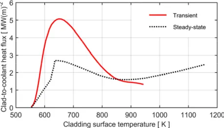
the NSRR. Both series of tests revealed significant kinetic effects in the clad-to-coolant heat transfer: typical transient and steady-state boiling curves measured for the PWR type testing conditions is shown in Figure 3. The critical heat flux was significantly higher in the transient tests than under steady-state conditions. The same was true for the critical surface temperature. In the film boiling regime, the magnitude of the heat flux was much different than under steady-state conditions. Typical values for these properties, measured in the transient tests as well as under steady-state conditions, are summarized in Table 1. It seems that the kinetic effects are most pronounced at NSRR conditions, probably as a consequence of the very high heating rate in these tests.
Figure 3: Typical boiling curves measured in the PATRICIA test loop, simulating transient heating and steady-state operating conditions
under PWR conditions [18]. See Table 1.
It is important to note that all PATRICIA tests were carried out with an Inconel tube as a proxy for a true fuel rod. The Inconel tube was free from surface oxide, in contrast to most fuel rods. The effect of a surface oxide layer on the clad-to-coolant heat transfer is strong, according to tests carried out in the NSRR; see section 2.2.2.1. It has also been shown that irradiation enhances clad-to-coolant heat transfer, at least under steady-state conditions. The effect is known as radiation induced surface activation (RISA) [19]. Another atypical feature of the PATRICIA
tests is that the Inconel tube was filled with air, and Joule heated by an electric current through the material. A cladding tube, on the other hand, is heated by a radial heat flux from the pellets, which have a significant thermal inertia. The importance of this difference in heating mode, as well as other atypical test conditions in the PATRICIA experiments, is discussed in [5].
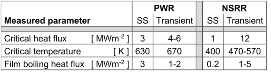
Table 1: Typical values of critical heat flux, critical surface temperature and film boiling heat flux, measured in PATRICIA tests under RIA-like
transients and steady-state (SS) conditions [5, 18].
PWR NSRR
Measured parameter SS Transient SS Transient
Critical heat flux [ MWm-2 ] 3 4-6 1 12
Critical temperature [ K ] 630 670 400 470-570
Film boiling heat flux [ MWm-2 ] 3 1-2 0.2 1-5
2.2.1.2 JAEA tests
Ex-reactor separate effect tests on clad-to-coolant heat transfer in simulated RIA conditions were carried out by the predecessor to the Japan Atomic Energy Agency (JAEA) in the late 1970s. The tests were done by immersing a heated Zircaloy-4 cylindrical rod into a pool with stagnant water with various degrees of subcooling. The resulting heat transfer phenomena were observed and recorded by high-speed photography, while at the same time, thermocouple measurements were made of the rod surface temperature versus time. These tests showed a strong effect of coolant subcooling on the transient heat transfer: as the subcooling increased, the time with high cladding temperature and film boiling became shorter and the quenching temperature increased [20]. The same effects of subcooling have later been observed in in-reactor tests.
2.2.1.3 MPEI tests
In the late 1980s, ex-reactor tests were carried out at the Moscow Power Engineering Institute (MPEI), Russia, in order to study clad-to-coolant heat transfer and kinetics of steam generation during RIAs [21, 22]. The tests were done on short fuel rod simulators that were transiently heated either by use of an electrical current through the material or by use of thermite mixtures. The rod simulators were immersed in room temperature water at atmospheric pressure inside a vessel made of optically pure quartz glass. Thermocouples were attached to the outer surface of the rod simulators, a pressure sensor was used for monitoring the water pressure and two He-Ne lasers were used for measuring the growth of the steam film at the rod surface during the tests. Unfortunately, it seems that only a few fragmentary results from these studies, in the form of plots over measured time histories for fuel rod surface temperature and steam film thickness, are available in the open literature [21, 22].
2.2.1.4 Tests on transient void formation
The peak power reached in a reactivity initiated accident is limited by inherent reactor feedback mechanisms. The most important of these mechanisms is the fuel temperature (Doppler) effect, but in light water reactors, the reactivity is also reduced by the water coolant temperature increase and steam (void) generation that follows shortly after the power pulse [23]. The kinetics of void formation in conditions typical for LWR design basis RIAs is poorly known, and for reasons of conservatism, the negative reactivity feedback from the transient void formation is usually neglected in coupled core neutronics/thermal-hydraulics computer analyses of these accidents [1]. However, substantial experimental work has been carried out in Japan to elucidate transient void formation in LWR RIA conditions. Early studies [24] have been followed by more elaborate experiments, where transient void generation has been studied around single fuel rods [25] as well as in rod bundle geometries [26].
2.2.1.5 Other tests on transient boiling heat transfer
Heat transfer under transient boiling conditions is a research field in itself, and studies exist that provide useful information on fundamental mechanisms and phenomena with relevance to LWR RIA conditions. However, these studies rarely furnish quantitative data that can be applied for calibration or validation of heat transfer models in computer codes for transient fuel rod analyses. The reason is that they are performed with non-prototypic heater configurations (wires, horizontal plates) or with fluids that are much different from water and steam: refrigerants with lower boiling temperature and much lower latent heat of vapourization than water are commonly used to ease the experimental work.
Early work of this kind is due to Derewnicki [27], who studied transient boiling heat transfer around electrically heated platinum wires immersed in water. A substantial amount of experimental work on transient boiling heat transfer from horizontal plates has been conducted over the last two decades by Auracher and co-workers, using both water and other fluids [13, 28]. More recently, experiments on transient boiling heat transfer have been conducted at IMFT, Toulouse University, France, using refrigerants in a vertical, semi-annual, flow channel. The geometry thus resembles that of a LWR fuel assembly sub-channel, and the experiments are aimed to improve the knowledge of transient boiling phenomena in RIA conditions [29, 30].
2.2.2 In-reactor tests
In-reactor RIA simulation tests have been carried out on short-length fuel rodlets in dedicated pulse irradiation reactors since the 1960s. Early tests, up to the late 1980s, were predominantly done on fresh fuel rods, whereas later tests have been done on rods that have been pre-irradiated to significant burnup in commercial power
reactors [1]. Some of the tests, especially those on fresh fuel, have been done on rodlets with thermocouples welded to the cladding surface. Time histories for the cladding outer surface temperature are available from these tests. These time histories are very valuable for calibration and validation of clad-to-coolant heat transfer models, but it should be recognized that the data are marred by large uncertainties. The uncertainties are related to the delayed response of the thermo-couples (about 20 ms) and the fact that they are in contact with both the cladding tube and the coolant, and that large fluid temperature gradients may exist in this boundary layer near the cladding surface. In addition, the thermocouples themselves disturb the local flow around them. This so called ”fin effect” is believed to lower the local temperature by about 100 K [31].
Moreover, detailed studies in the NSRR suggest that film boiling under RIA is a very local phenomenon. Measured temperatures often differ by several hundreds of kelvin between thermocouples, although their spacing is just a few centimetres. Post-test measurements of Vickers hardness of the cladding also bear witness to large axial and circumferential variations in peak cladding temperature during the transient [32]: since softening of irradiated cladding by annealing of radiation damage occurs in about 10–15 s at temperatures above 850 K, it is possible to determine that a boiling crisis has occurred during the test by the resulting drop in Vickers hardness [33]. These measurements often indicate peak cladding tempera-tures that are higher than those measured by thermocouples [32].
2.2.2.1 NSRR tests
The most abundant source of data on cladding temperature histories for in-reactor RIA simulation tests originates from tests in the NSRR, Japan. Most of these data were produced in early testing programs on fresh fuel rods, which were aimed to investigate the effects of fuel design and cooling conditions on the fuel rod behaviour during RIAs. General reviews of these early testing programs can be found elsewhere [16, 34]. Later testing programs have been conducted with pre-irradiated fuel rodlets, and the focus has been to investigate the effects of fuel burnup on the fuel rod behaviour [1].
Results from early tests, pertaining specifically to clad-to-coolant heat transfer in simulated RIA conditions, have been reported by Fujishiro and co-workers [35]. A large number of tests were carried out on fresh fuel rods, which were pulse irradiated to a fixed energy deposition of 795 J(gUO2)-1 in the NSRR. The water
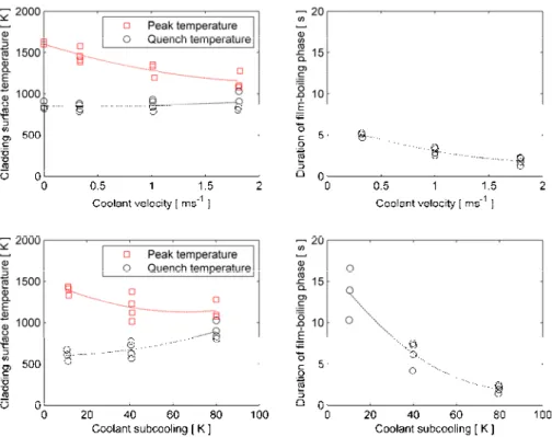
coolant was at atmospheric pressure in all tests, but the coolant temperature and flow rate were varied for parametric studies. While the flow rate had a strong effect on the peak cladding temperature, the film boiling duration and the quenching temperature were controlled mainly by the subcooling [35]; see Figure 4.
From a recent evaluation of in-reactor heat transfer tests in the NSRR, it was concluded that the heat transfer from the cladding surface to the coolant water is improved by increasing the coolant subcooling, the coolant pressure, and the coolant
heat transfer in a consistent way, regardless of the other cooling parameters under consideration, i.e. the coolant pressure and flow velocity. The latter parameters, on the other hand, were reported to have more ambiguous effects on the heat transfer. The data compiled in [37] are open to the public and very useful for validation and calibration of clad-to-coolant heat transfer models for RIA conditions.
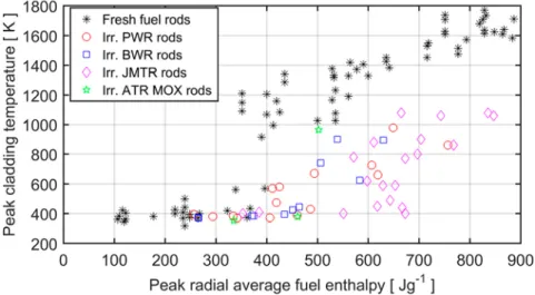
Later testing programs in the NSRR, conducted on pre-irradiated fuel rods, have revealed significant differences in clad-to-coolant heat transfer between fresh and irradiated fuel. For comparable energy injections, pre-irradiated test rods show lower cladding surface temperatures than fresh rods without a surface oxide layer. Figure 5 summarizes the peak cladding surface temperatures that have been recorded in NSRR tests on fresh and pre-irradiated fuel rods. All tests were done with near-zero initial rod power and enthalpy, and the coolant was stagnant water at ambient temperature and atmospheric pressure.
Figure 4: Influence of coolant velocity and subcooling on film boiling conditions. Results from NSRR pulse-irradiation tests on fresh PWR
fuel rods [35]. All tests were done at atmospheric pressure with an energy deposition of 795 J(gUO2)-1. The upper figures show results
for a fixed subcooling of 80 K, and the lower figures show results for a fixed coolant velocity of 1.8 ms-1.
It is clear from Figure 5 that fresh fuel rods behave differently from pre-irradiated rods. The enthalpy threshold at which a boiling crisis occurs is more distinct for the fresh rods, and the peak cladding surface temperature under film boiling is generally higher than for pre-irradiated fuel. A possible explanation to these differences is that the oxide layer on the pre-irradiated fuel rods increases the wettability of the
cladding surface, thereby improving cladding-to-coolant heat transfer. To verify this hypothesis, a series of pulse irradiation tests were done in the NSRR, using un-irradiated PWR fuel rods of 17×17 design with three different surface states: fresh test rods without oxide, autoclaved rods with 1 μm oxide thickness, and rods with 10 μm oxide. All test rods were instrumented with cladding surface thermocouples [17]. Transient records of the cladding surface temperature showed that the critical heat flux and the minimum heat flux were generally higher for the pre-oxidized than for the non-oxidized rods. Moreover, the duration of film-boiling was shorter for the pre-oxidized rods. However, no significant difference could be seen between rods with 1 μm and 10 μm oxide. Based on the latter observation, it was proposed that the oxide-induced improvement of surface wettability is caused by a change in chemical potential rather than a change in surface roughness [17]. Other possible contri-butions to the observed differences in transient thermal behaviour between fresh and preirradiated rods are discussed in [32]. Effects of pre-transient changes to the state of fuel and cladding are identified, such as cladding corrosion, fuel cracking and fragment relocation, and changes to the thermal conductivity of the fuel pellet and the pellet-cladding gap.
Figure 5: Peak cladding surface temperatures, measured by thermocouples under RIA simulation tests in the NSRR. The coolant is stagnant water at
room temperature and atmospheric pressure in all the tests.
If a boiling crisis occurs, the peak cladding temperature is correlated to the energy deposition, as shown in Figure 5, and the same is true for the duration of the film-boiling phase. A film-film-boiling phase with high cladding temperature for 2–15 s is reported from the RIA simulation tests on instrumented rodlets in the NSRR [16, 35, 38]. The peak cladding temperature and the time at high temperature decrease with increasing coolant flow rate and subcooling.
2.2.2.2 Other tests
Some RIA simulation tests have been conducted on test rodlets instrumented with cladding thermocouples also in other pulse reactors than the NSRR. However, the available information on these tests, including the measured cladding temperature histories, is in most cases insufficient for validation and calibration of computational models. For example, some tests on fresh VVER fuel rods, equipped with 2–6 thermocouples for on-line measurement of cladding temperature versus time during the test, have been done in the IGR pulse reactor, Kazakhstan. The measured data were used in Russia for validation of heat transfer models in the computer programs FRAP-T and SCANAIR, but the tests and the resulting temperature data are only fragmentarily described in the open literature [39]. The cooling conditions in these tests, stagnant water at room temperature and atmospheric pressure, are identical to the standard conditions in the NSRR, but the pulse widths used in the tests are very different: the NSRR produces 4–7 ms wide pulses, while pulses in the IGR are 600-950 ms wide [1].
Measured cladding temperature histories are also available from the Special Power Excursion Reactor Tests IV (SPERT-IV), conducted in the USA during the 1960s. Information on these early tests is given in [40] and references therein. In short, the tests were done in an open pool type reactor with room temperature water as coolant. The pool had a 5.5 m hydrostatic head above the reactor, which means that the coolant pressure in the core was about 0.15 MPa. Tests were done with coolant flow rates from 0 to 4 ms-1 and with power pulses having initial reactor periods1
between 7 and 980 ms. All pulses started from very low reactor power. The core consisted of aluminium-clad plates of highly enriched uranium, and the measured temperature data pertain to the surface of the aluminium cladding. It seems that only a very few tests resulted in a boiling crisis; with a few exceptions, the cladding temperature rise during the test was below 170 K [40].
Measured time histories for cladding surface temperature are also available for two rodlets in the RIA 1-2 test series, conducted in the Power Burst Facility (PBF), USA. These tests were done with coolant conditions that were very close to those in a BWR (538 K, 6.45 MPa and 0.4 ms-1), and the pulse widths were also fairly
prototypic (16 ms). This makes the data valuable for model validation [41, 42]. The test rodlets had a burnup around 5 MWd(kgU)-1 and a cladding oxide layer
thickness of about 5 µm. The peak fuel pellet radial average enthalpy reached 775 J(gUO2)-1 during the tests, and both rodlets survived the tests without cladding
failure. Each rodlet was instrumented with cladding thermocouples at two different axial positions. The measured temperature histories from the thermocouples were verified by metallographic examinations of the cladding and by measuring the
1 The initial reactor period is the time needed for the initial reactor power to change
by a factor e (2.72). Hence, the pulses in SPERT-IV were comparatively wide in comparison with those in the NSRR or other pulse irradiation reactors..
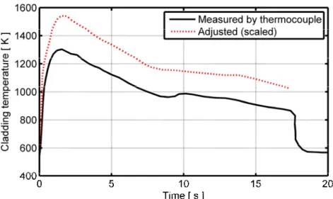
cladding oxide layer thickness after the tests. The results of these post-test measurements indicated that the thermocouple readings underestimated the true cladding temperatures, presumably because of the aforementioned fin effect. For this reason, the temperature histories were adjusted (scaled) such that the calculated post-test oxide layer thickness matched the measured data. An example is shown in Figure 6. The results suggest that the thermocouple readings should be interpreted as a lower bound for the true cladding surface temperature, and that some adjustment of the raw data is needed to estimate the latter.
Figure 6: Cladding surface temperature for axial position 0.46 m of PBF RIA 1-2 test rod 802-2. The adjusted temperature is based on post-test
measurements of the cladding oxide layer thickness [41].
2.3 Modelling
2.3.1 General
Computational models for clad-to-coolant heat transfer in RIA conditions are needed in two different categories of computer programs: codes used for core-wide neutron kinetics analyses of the accidents and codes used for detailed studies of the thermal-mechanical response of individual fuel rods to the accidents [1]. Today, there are about a dozen computer programs in the latter category, which are used worldwide for thermal-mechanical fuel rod analyses of postulated RIAs in LWRs and for interpretation of RIA simulation experiments performed in pulse reactors. As mentioned in section 1, an international benchmark for these computer programs was initiated in 2011 by the OECD/NEA/CSNI/WGFS. Phase I of this benchmark, which was concluded in 2013, revealed large differences between the computer programs [2]. Phase II of the benchmark was aimed at elucidating these differences, which were particularly apparent in the applied models for clad-to-coolant heat transfer [3].
Thermal-mechanical fuel rod analysis codes applied to RIAs typically contain two kinds of sub-models for calculating clad-to-coolant heat transfer: a thermal-hydraulic model for the coolant fluid and a library of correlations for the clad-to-coolant heat transfer coefficient in the different heat transfer regimes expected during the accident [3]. The thermal-hydraulic models applied for the coolant are generally one-dimensional, meaning that they consider only axial flow and axial gradients in fluid properties: the physical properties of the fluid are assumed to be constant all over the flow channel cross-section for a given axial elevation. The complexity of the coolant thermal-hydraulic models varies considerably among the computer codes. The simplest approaches consider the one-dimensional energy and mass balance equations for single phase (liquid) water, whereas the most complex consider two-phase (liquid and steam) one-dimensional flow with mass, momentum and energy balance equations for each phase.
The libraries of correlations applied for the clad-to-coolant heat transfer coefficient also vary among the fuel rod analysis codes. Most of the correlations in use today originate from non-RIA applications, although there are a few codes that make use of empirical correlations that have been fitted directly to data from RIA simulation tests [5, 6, 36]. The non-RIA correlations generally underestimate the critical heat flux and the clad-to-coolant heat transfer coefficient in the film boiling regime, and empirical scaling factors must be introduced for the correlations to reproduce cladding temperatures observed in RIA simulation tests. These scaling factors are introduced in an ad-hoc manner for a particular set of tests, e.g. NSRR tests with stagnant water coolant at room temperature and atmospheric pressure, and it is unclear to what extent the same scaling factors apply to other coolant conditions.
2.3.2 SCANAIR
As mentioned in section 1 of this report, SCANAIR V_7_5 and later versions of the program are equipped with two different modules for modelling coolant thermal-hydraulics and clad-to-coolant heat transfer. These modules are briefly described below.
2.3.2.1 Standard single-phase coolant module
A concise description of the standard module for coolant thermal-hydraulics and clad-to-coolant heat transfer in SCANAIR can be found in [4]. The model for coolant thermal-hydraulic calculations is restricted to single phase fluids and treats either liquid sodium or liquid water. The conservation equations for mass and energy of the liquid are solved in one-dimension, using the liquid temperature and mass flow rate at the lower end of the vertical coolant channel as time-dependent input to the calculations. The coolant pressure is also given as time-dependent input to the calculations: it is assumed to be uniform, since the conservation equation for momentum is not solved by the model. The coolant channel is discretized into the same number of axial segments (nodes) as the fuel rod, and the physical properties
of the coolant are assumed to be uniform (radially and axially) within each axial segment. The cross-sectional area of each axial segment is continuously updated to account for any cladding deformation during the simulated accident. Output from the coolant model comprises the calculated coolant temperature and flow rate in each axial segment.
Heat transfer between the coolant and the cladding tube, and possibly also between the coolant and an enclosing shroud or capsule, is calculated in each axial segment of the discretized coolant channel. The clad-to-coolant heat transfer is calculated for each segment separately by use of a set of correlations for the clad-to-coolant heat transfer coefficient and the clad-to-coolant critical heat flux. Part of the correlations are well-known relations intended for modelling of steady-state heat transfer or slow transients in typical PWR or pool conditions, while others are specifically developed for analyses of RIAs with SCANAIR. The latter category of correlations are based on results from ex-reactor PATRICIA tests under simulated PWR conditions [5] and in-reactor NSRR tests, carried out on fresh fuel rods with stagnant water at room temperature and atmospheric pressure as a coolant [6]. Guidelines and recom-mendations regarding the choice of correlations and tuning parameters to use for the PWR and NSRR cooling conditions are provided as part of the SCANAIR user’s manual [43]. For other cooling conditions, it is left to the user to find an appropriate set of correlations and empirical tuning parameters.
The cladding heating rate does not enter directly as a parameter into the clad-to-coolant heat transfer correlations in the standard single-phase clad-to-coolant module, but some of the correlations are designed such that transient effects can be considered indirectly by empirical relations. For example, the critical surface temperature Tcrit
can be scaled with a factor that depends on the time spent in nucleate boiling; see Figure 1. An increase of the critical heat flux in a fast transient, characterized by a short period of nucleate boiling, can thereby be modelled.
2.3.2.2 Optional two-phase coolant module
The fundamental design of the optional two-phase coolant module QT-COOL is similar to the standard single-phase coolant module in SCANAIR: it contains a one-dimensional thermal-hydraulic model for the coolant, implemented in the same discretized geometry as the single-phase model, and a library of correlations for the clad-to-coolant heat transfer coefficient and the clad-to-coolant critical heat flux. However, the thermal-hydraulic model considers two-phase water by treating the liquid-steam mixture as a homogeneous pseudo fluid that obeys the usual equations of a single phase fluid [9]. The one-dimensional conservation equations for energy and mass are solved for the pseudo fluid, but not the momentum equation. Consequently, the coolant pressure must be defined as time-dependent input. Moreover, the mass flow rate and specific enthalpy2 at the lower end of the vertical
2 Since the two phases are assumed to be in thermodynamic equilibrium, the specific
liquid-coolant channel must also be given as time-dependent input by the user. Output from the coolant model comprises the calculated coolant temperature, phase composition and flow rate in each axial segment. It is not possible to model sodium coolant with the QT-COOL module, and any heat transfer from the coolant to an enclosing shroud or capsule is neglected.
The QT-COOL module contains a fairly large library of correlations for the clad-to-coolant heat transfer coefficient and the clad-to-clad-to-coolant critical heat flux. All the correlations are well-known relations for modelling steady-state heat transfer and slow transients. Since none of them is intended specifically for RIA conditions, the user is given the possibility to scale the calculated critical heat flux and the film boiling heat transfer coefficient by setting scale factors as input to the module [10]. In contrast to the standard single-phase coolant module in SCANAIR, the QT-COOL module is intended for application also to BWR conditions, and for this reason, the library of correlation has a wider scope. It contains clad-to-coolant heat transfer correlations for typical PWR, BWR and pool cooling conditions [9].
3 Assessment of coolant inertia effects
As mentioned already in section 1 of the report, the steady-state heat transfer models in the QT-COOL coolant channel module underestimate the clad-to-coolant heat transfer under transient film boiling. Earlier work [10] has shown that, in general, the clad-to-coolant heat transfer coefficient in the film boiling regime has to be increased by an order of magnitude in order to reproduce measured cladding temperature histories from RIA simulation tests in the NSRR. In fact, this finding is not restricted to QT-COOL. Similar results have been obtained by others when simulating NSRR experiments with fuel rod codes that use steady-state models for the clad-to-coolant heat transfer: the transient film boiling heat transfer is generally underestimated by steady-state models.
A possible explanation to these results is that the thickness of the continuous steam film that forms at the cladding surface during fast heating is overestimated by steady-state film boiling models. The growth of the film is rate controlled either by the transfer of heat and mass across the steam-liquid interface, or by inertia of the surrounding liquid that has to be displaced for the film to grow. In section 3.1 below, we use a simple model to investigate if the inertia effects are important enough to affect the growth rate of the steam film.
Inertia may also have a rate controlling effect on steam generation on a large scale. If the water coolant is at (or near) saturated conditions, heat transferred from the fuel rod to the coolant will vapourize the liquid and increase the steam (void) fraction of the two-phase fluid. Since the vapourization involves a significant volume expansion, it will lead to a local pressure increase that will accelerate and displace the coolant axially along the flow channel. The axial flow is rate controlled by the vapourization rate, inertia of the displaced coolant and friction losses in the coolant channel. Since neither inertia nor friction is considered by the coolant thermal-hydraulic model in QT-COOL, the module overestimates the axial flow rate upon vapourization.
An example of this shortcoming is given in Figure 7, which pertains to case 6 in Phase II of the WGFS RIA fuel code benchmark [3, 44]. This benchmark case simulates an RIA under cold zero power BWR conditions, and considers a fuel rodlet with an active (fuelled) length of 0.10 m, surrounded by stagnant water; see the schematic drawing in Figure 7. The water is at atmospheric pressure and initially at room temperature. It is contained in an annular flow channel with an outer radius of 7.5 mm. The hydraulic diameter of the flow channel is similar to that in a typical fuel assembly. The fuel rodlet is subjected to a triangular power pulse, resulting in a total energy deposition of 9 kJ. This energy is sufficient to vapourize about 35 % of the water in the coolant channel.
Figure 7 shows the coolant velocity and steam fraction, calculated for the uppermost axial segment of the coolant channel with QT-COOL, implemented in SCANAIR
V_7_2 [10]. After the power pulse, the water temperature increases gradually as heat is transferred from the rodlet, and vapourization is calculated to start 923 ms after the power pulse. Since the coolant is at atmospheric pressure, the vapourization leads to a volume expansion by a factor of 1625. Within fractions of a millisecond, the coolant axial velocity at the upper end of the coolant channel reaches about 25 ms-1. Since a homogeneous equilibrium model is used for the two-phase coolant, the
steam and liquid are assumed to have the same velocity. As a consequence, most of the liquid is ejected from the coolant channel together with the expanding steam, and the coolant steam fraction tends to unity after about 50 ms.
Figure 7: Calculated coolant conditions at the top of the coolant channel for case 6 in Phase II of the WGFS RIA fuel code benchmark [44]. The calculated results shown in Figure 7 are unrealistic. In reality, the coolant axial velocity will increase gradually over a longer period of time and reach a lower peak value, due to inertia and friction effects. Moreover, the liquid phase will have lower velocity than the steam phase, because of inertia, and less liquid will be lost from the flow channel than calculated with the homogeneous equilibrium model in QT-COOL. In section 3.2 below, we investigate the calculated results from Figure 7 by use of a simple model for uniaxial flow that accounts for inertia effects.
3.1 Annular vapour film formation
Consider a fuel rod with cladding outer radius Rco, which is surrounded by
subcooled liquid water. The rod is rapidly heated, such that an annular vapour film forms at the cladding surface and grows outward. Assuming axial symmetry, the radial position of the vapour-liquid interface is Ri(t), with the initial condition
Let us assume that the vapour film grows to a thickness within a time interval . More precisely, we assume that the growth is described by the following simple functional relationship for Ri over the time span 0 < t < :
3 2 2 3 ) ( t t R t Ri co . (1)
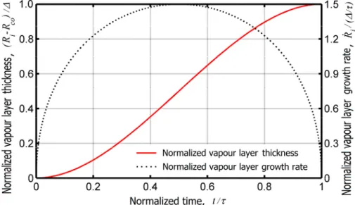
Equation (1) is plotted in normalized form in Figure 9, together with the normalized radial velocity of the vapour-liquid interface. The velocity is zero at t = 0, passes through a maximum of 3/2 at t = /2, and approaches zero as the vapour layer tends to its full thickness, . Equation (1) is a postulated relationship for the vapour layer growth, chosen because of its simplicity. It captures the most important para-meters of the vapour layer growth ( and ), and as will be seen later, it is adequate for our simple assessment.
Figure 8: Assumed geometry of heated fuel rod and growing vapour film.
Figure 9: Normalized thickness and growth rate for the growing vapour film. A prerequisite for the postulated growth of the vapour film to take place is that a radial pressure gradient exists in the liquid. We may estimate the magnitude of this
momentum) for the liquid outside the vapour film. Since we are merely interested in an estimate of the radial pressure gradient, we consider the simplest possible description of the fluid and neglect viscosity, compressibility and gravity. We also assume that the fluid density, l, is constant and uniform, which means that the fluid
velocity and pressure vary only with the radial coordinate, r. Moreover, the fluid velocity is in the radial direction only, and we denote this radial velocity component
u(r,t). For this situation, the Euler equations become [45]
0 ) ( 1 r ru r , (2) 0 r p r u u t u r p Dt Du l l , (3)
where p is the liquid pressure and Du/Dt denotes the material (convective) derivative. From eq. (2), which is the conservation equation for mass, we find a solution to the velocity field that satisfies the boundary condition u(r=Ri,t) = Ri(t)
r t R t R t r u i i() () ) , ( . (4)
Here, Ri Ri/t refers to the postulated velocity of the vapour-liquid interface,
which can be calculated by differentiation of eq. (1).
By use of eq. (4) inserted into eq. (3), which is the conservation equation for momentum, we find a general solution to the axisymmetric pressure field
2 2 2 ) / ln( ) ( ) ( ) , ( r R R R r R R R R t H t r p l i i i i i i i l , (5)
where H(t) is a general function of time, and Ri is the acceleration of the
vapour-liquid interface. The latter can be calculated as a function of time from eq. (1). By use of eq. (5), we may finally estimate the pressure difference between the vapour-liquid interface and a position r =R, far from the interface. More
specifically, by interpreting H(t) in eq. (5) as the pressure at the vapour-liquid interface, henceforth called pi(t), we may re-write eq. (5) as
2 2 2 ) / ln( ) ( ) , ( ) ( R R R R R R R R R t R r p t p l i i i i i i i l i . (6)
Since R Ri, a fair approximation to eq. (6) is given by
) / ln( ) ( ) ( l i i i i i i t RR RR R R p , (7)
where pi(t) pi(t)p(rR,t) is the local overpressure at the vapour-liquid
interface. Equation (7) is plotted in Figure 10 for the case of l = 103 kgm-3, Rco = 5
mm, R∞ = 10Rco and = 1 mm, assuming different values for the vapour layer
formation time, . The maximum overpressure at the vapour-liquid interface is reached in the initial growth phase, when the acceleration of the interface (Ri) is at
) / ln( 6 ) 0 ( l 2co co i R R R t p . (8)
Typical bounding values for the parameters on the right-hand-side of eq. (8) are l =
103 kgm-3, Rco = 5 mm, = 2.0 mm, and = 10 ms. With these values and R∞ =
10Rco, we find that pi(t=0) is about 1.4 kPa. Hence, we may conclude that a vapour
film with a thickness of several millimetres may form within 10 ms with only a minor increase in local pressure at the vapour-liquid interface. In other words, the inertia of the liquid surrounding the vapour film seems to have only a negligible impact on the vapour film growth rate. This conclusion is based on a simple analysis of an inviscid liquid and with an assumed growth behaviour for the vapour film. However, even if a more refined model would yield different results, the differences are not likely to be large enough to change the conclusion.
Figure 10: Overpressure at the liquid-vapour interface, calculated through eqs. (1) and (7) with l = 103 kgm-3, Rco = 5 mm, R∞ = 10Rco and = 1 mm.
3.2 Bulk vapour generation and coolant axial flow
Next, let us consider one-dimensional axial flow in a vertical flow channel, as illustrated by the drawing in Figure 7. More precisely, we will study case 6 in Phase II of the WGFS RIA fuel code benchmark [44]. Neglecting viscosity and friction losses from the channel walls, the conservation equation for momentum of the fluid is given by 0 g z p z v v t v g z p Dt Dv , (9)
where and v(z,t) are the density and axial velocity of the fluid, p is the pressure, z is the axial position and g = 9.81 ms-2 is the gravitational acceleration. As a
first-order approximation, we may apply eq. (9) to a finite control volume, given by the annular coolant flow channel in Figure 7. As already mentioned, this flow channel was 0.10 m long for case 6 in Phase II of the WGFS RIA fuel code benchmark. It was closed at its lower end, meaning that the fluid axial velocity was zero at this
position. The calculated velocity at the upper end, vo, is plotted versus time in Figure
7. For the centre of the flow channel, halfway between the lower and upper end, we may approximate the derivatives in eq. (9) as follows:
t v t v t v t v o l z z 2 1 2 1 0 , (10) l v l z v l z v l z v z v z v v o2 2 1 ) 0 ( ) ( 2 ) ( ) 0 ( , (11)
where l = 0.10 m is the length of the flow channel. Since the fluid axial velocity at the upper end of the flow channel, vo, is calculated versus time by QT-COOL, it is
also possible to obtainvo tfrom the calculated results; see Figure 7. By inserting
the approximations from eqs. (10) and (11) into eq. (9), we get the following estimate for the axial pressure gradient in the coolant channel
l v t v g z p 2 o o2 2 . (12)
The fluid density in eq. (12) decreases with time as the steam fraction in the homogeneous two-phase mixture increases. At atmospheric pressure, the density of saturated liquid water and steam is 959 and 0.59 kgm-3, respectively. Here, we use
the calculated time history for the average density in the coolant channel, combined with the calculated coolant velocity at the upper end of the channel, to estimate the pressure gradient through eq. (12). The calculated results for case 6 in Phase II of the WGFS RIA fuel code benchmark is shown in Figure 11. Obviously, a significant axial pressure gradient that lasts for about 0.3 ms is associated with the rapid axial acceleration of the coolant; compare Figure 7.
Figure 11: Estimated axial pressure gradient in the coolant for case 6 in Phase II of the WGFS RIA fuel code benchmark [44]. Calculated through
The results put forth in Figure 11 suggest that inertia effects connected with rapid vapourization cannot be neglected and that the assumption of a uniform pressure along the coolant channel is not justified. Hence, the governing equations solved by QT-COOL (mass and energy conservation for the homogeneous two-phase mixture) should be supplemented by a simultaneous solution of the momentum conservation equation in order to determine the space-time variation of the coolant pressure. This would provide calculated results with:
A local pressure increase in any coolant channel segment where vapourization occurs. This pressure increase will restrict the vapourization by raising the local saturation temperature, and it will also reduce the volume occupied by the generated steam. Hence, the vapourization will be slower and lead to less volume expansion.
Long-range axial pressure gradients, extending from axial regions where liquid is vapourized towards the open end(s) of the coolant channel.
A slower axial acceleration of the coolant when liquid is vapourized, leading to slower and more gradual ejection of fluid from the coolant channel.
4 Conclusions and recommendations
Our review of experiments and data in section 2.2 of the report reveals that heat transfer from a solid surface to water and/or steam is affected by the heating rate of the surface. In general, the critical heat flux and film boiling heat transfer coefficient for the surface increase with increasing heating rate. These transient effects are observable already at heating rates that are much lower than those expected for the fuel rod cladding under design basis RIAs in LWRs. A widely accepted hypothetical explanation to the observed differences between transient and stationary conditions is that the temperature gradient in the fluid close to the surface may be much steeper under fast heating than under stationary conditions, since the time is insufficient for conduction and convection to transfer heat away from the surface even on the local scale. The liquid close to the surface may also be significantly superheated under fast heating conditions, since the fluid is not in thermodynamic equilibrium.
The above hypothesis calls for two-dimensional (axial-radial) models for the coolant that surrounds the fuel rod, instead of the one-dimensional (axial) models that are typically used in computer programs for fuel rod thermal-mechanical analyses today: two-dimensional models would be needed to resolve the radial gradients in coolant properties at a local scale. Early versions of the SCANAIR computer program contained a link to such a two-dimensional coolant channel module, developed at the Kurchatov Institute (KI), Russia [46], but this link has been removed in later versions of the program. We also note that researchers at the MPEI have proposed two-dimensional coolant channel models for analyses of reactivity initiated accidents [21, 22], but it seems that neither the KI nor the MPEI model is in use today. The reason is unclear, but it may be due either to the complexity and computational cost involved with multi-dimensional, multi-phase flow models, or to the difficulties in calibrating and validating these elaborate models against the limited amount of data at hand from transient heat transfer experiments.
In one-dimensional models for the coolant channel around the fuel rod, one has to account for the transient heating effects on the radial gradients in some other way. The prevalent approach is to use heat transfer models for stationary conditions, and to introduce empirical tuning factors into these models that make them reproduce results from transient heat transfer experiments. The tuning factors are usually introduced in an ad-hoc manner for a particular set of tests, e.g. NSRR tests with stagnant water coolant at room temperature and atmospheric pressure, and it is unclear to what extent the same tuning factors apply to other coolant conditions. An interesting approach, which has been proposed but not yet tested [47], is to introduce tuning factors that depend explicitly on the cladding heating rate into the stationary heat transfer models. For example, a correlation for the clad-to-coolant heat transfer coefficient in the film boiling regime, hfb, could be expressed as
) 1 ( tfb/ ss fb fb h Ae h . (13) Here, ss fb
h is the heat transfer coefficient calculated for stationary conditions by use of well-established correlations, tfb is the time spent in film boiling, is a
charact-eristic time related to radial heat transfer by conduction and convection in the coolant, and A is a function of the cladding heating rate at start of film boiling and the coolant subcooling. The parameters A and are empirical and should be fitted to experimental data. We know from earlier work that A = 12 makes SCANAIR in combination with the QT-COOL coolant channel module reproduce measured cladding temperature histories from RIA simulation tests in the NSRR with stagnant water coolant at room temperature and atmospheric pressure [10]. For the correlation in eq. (13) to work also for stationary conditions, one should require that
0
A when the cladding heating rate at start of film boiling tends to zero. A tuning factor that gradually declines with the time spent in film boiling, as in eq. (13), is in fact already used in the standard single-phase coolant module in SCANAIR. However, the time-dependent decline is modelled as linear rather than exponential [6, 43].
In order to find reasonable expressions for the empirical tuning parameters A and in eq. (13), one may use simple models to study possible transient effects on the film boiling heat transfer. In section 3.1 of the report, we used a simple hydrodynamic model to investigate if the heat transfer could possibly be affected by inertia of the liquid water that surrounds the growing vapour film at the cladding surface. The hypothesis was that the growth of the insulating film could be rate controlled by inertia of subcooled liquid that is displaced radially by the growing film. This would lead to a thinner vapour film during transient heating than under stationary conditions, resulting in a better clad-to-coolant heat transfer. Hence, the hypothesis could help explain the observed difference between transient and stationary film boiling heat transfer and also provide an estimate for in eq. (13). However, the hypothesis proved to be wrong. For conditions expected under RIAs in LWRs, the growth of the vapour film seems to be rate controlled by transfer of heat and mass across the liquid-vapour interface rather than by inertia of the liquid that is displaced radially by the growing film.
On the other hand, our assessment of axial flow in section 3.2 indicates that the coolant inertia is important for the axial flow kinetics in the coolant channel when the accident conditions are such that net vapour generation occurs anywhere along the fuel rod. The reason is that the vapourization involves a large local volume expansion, which in turn entails acceleration and displacement of a significant amount of water along the coolant channel. It should be remarked that our assessment in section 3.2 concerned a case with a short (0.10 m) coolant channel. The effects of inertia on the kinetics of vapourization and coolant axial flow will be more pronounced in a full-length (3.6 m) commercial LWR fuel rod.
![Figure 1: Schematic boiling curve, also referred to as Nukiyama curve [12]. Here, T sat is the saturation temperature of the fluid and q crit and T crit](https://thumb-eu.123doks.com/thumbv2/5dokorg/3337696.18396/17.892.231.654.597.915/figure-schematic-boiling-curve-referred-nukiyama-saturation-temperature.webp)
![Figure 2: Mechanisms for boiling crisis in single phase liquid water under quasi-stationary and transient conditions [6]](https://thumb-eu.123doks.com/thumbv2/5dokorg/3337696.18396/19.892.201.696.214.508/figure-mechanisms-boiling-crisis-single-stationary-transient-conditions.webp)
![Figure 7: Calculated coolant conditions at the top of the coolant channel for case 6 in Phase II of the WGFS RIA fuel code benchmark [44]](https://thumb-eu.123doks.com/thumbv2/5dokorg/3337696.18396/32.892.220.672.355.648/figure-calculated-coolant-conditions-coolant-channel-phase-benchmark.webp)