Master of Science Thesis
KTH School of Industrial Engineering and Management Energy Technology EGI-2015-070MSC EKV1107
Division of Heat & Power SE-100 44 STOCKHOLM
Commissioning the Heating and
Cooling Systems on an FPSO
(Floating Production Storage and
Offloading facility)
Cyril ADOLPHE
Master of Science Thesis EGI-2015-070MSC EKV1107
Commissioning the Heating and Cooling Systems on an FPSO (Floating Production
Storage and Offloading facility)
Cyril Adolphe
Approved
2015-08-25
Examiner
Miroslav Petrov - KTH/ITM/EGI
Supervisor at KTH
Miroslav Petrov
Commissioner
ACTEMIUM (VINCI ENERGIES)
Contact person at industry
Thomas Seligmann
Abstract
The project under discussion is the FPSO Ichthys. The FPSO is a ship comprising the offshore production facility for an oil&gas field, financed by INPEX/Total. An oil platform extracts the product received via the flexible risers and separates it into gas and condensate. The condensate is transferred to the FPSO, which processes it, and separates it between natural gas and oil. The oil is stored in the FPSO and then exported via a tanker. The gas is transferred via a pipeline.
An FPSO is a complex installation in many respects. It is a condensate treatment factory, installed on a 450-metre-long ship. It should have the capacity to store one week’s condensate production. The FPSO is self-sufficient in terms of energy production (electricity, heating and cooling). Owing to the proximity of the hazardous production area to the living quarters, strict safety regulations are applied. For instance, all equipment has to be designed with redundancy (2x50% or 3x33% for critical equipment); the heating and cooling systems are managed with the help of emergency logic diagrams. These enable vital functions to
be maintained even in cases of extreme failure.
Despite its complexity, the FPSO has to be constructed within a short period of time. However, safety issues are important, and maintenance of defective equipment is expensive since the ship will be located 300km away from the coast. This is the reason why the constructor contracted Actemium, a part of VINCI Energies. Actemium commissions the FPSO. The commissioning mission has to prove that the systems function in accordance with the designs. Commissioning occurs right after the pre-commissioning (de-energized verifications). Commissioning is divided into three main activities: functional tests (which prove that individual pieces of equipment work in accordance with the designs); operational tests (which prove that all subsystems work in accordance with the designs of different modes); and piping and vessels pressurization (which prove that there is no leak).
This master thesis describes the requirements of such projects and focuses on the operational tests. A description of the installation is detailed. Secondly, the subcontractor for the commissioning of the project, Actemium, and the method used for the commissioning are presented thereafter. Finally, the operational test procedures of the cooling and heating systems are examined in detail.
-i-
Contents
1 INTRODUCTION ... 1 2 PROJECT BACKGROUND ... 2 2.1 Ichthys Project ... 2 2.2 Ichthys FPSO ... 2 2.2.1 General description ... 22.2.2 Heating and cooling requirements ... 3
2.3 Annex Installations ... 4
2.3.1 Subsea ... 4
2.3.2 CPF ... 5
2.3.3 Gas Export Pipeline ... 6
2.3.4 LNG Plant... 6
3 THE COMPANIES ... 7
3.1 Client ... 7
3.2 Constructor ... 7
3.3 Main equipment vendors ... 8
3.4 Sub-contractor for the Commissioning ... 8
3.5 Certification Company ... 8
4 THE INSTALLATION ... 9
4.1 Base of design ... 9
4.2 Description of the System ...11
4.2.1 Cooling Medium System ...11
4.2.2 Heating medium system ...12
5 METHODOLOGY OF THE COMMISSIONING ...17
5.1 Methodology OPERCOMTM and ICAPS© ...17
5.2 Project Organization ...17
5.3 Pre-commissioning Activities ...18
5.4 “Commissioning” activities ...20
5.5 Start-up Activities ...21
5.6 Engineering Documents ...22
5.7 Commissioning: Onshore and Offshore ...23
6 HEATING AND COOLING SYSTEMS OPERATIONAL TEST PROCEDURES ...24
6.1 General Planning ...24
6.2 Cooling System ...24
6.2.1 Activity completion ...24
-ii-
6.2.3 Control Philosophy ...26
6.2.4 Post-operational Test ...30
6.3 Heating System ...30
6.3.1 Activity completion ...30
6.3.2 Pre-requirement of the OTP for the heating medium system ...30
6.3.3 Control Philosophy ...31 6.3.4 Post-operational Test ...45 7 CONCLUSION ...46 REFERENCES ...47 APPENDIX 1 ...48 APPENDIX 2 ...49 APPENDIX 3 ...50
-iii-
List of Figures
Figure 1: Schematic of the Ichthys LNG project ... 2
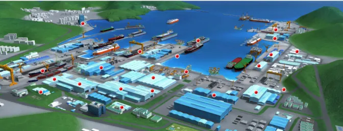
Figure 2: 3D model of the FPSO ... 3
Figure 3: 3D-exploded view of the FPSO with the area of concern ... 4
Figure 4: 3D model of the Ichthys CPF ... 5
Figure 5: Localization of the Ichthys FPSO, CPF and the LNG facility connected by pipeline ... 6
Figure 6: 3D Plan of the DMSE yard ... 7
Figure 7: Comparison between normal project and a project under the OPERCOM philosophy ...18
Figure 8: Summary of the pre-commissioning activity ...19
Figure 9: Summary of the commission activity ...21
Figure 10: Seawater required capacity for operational tests ...25
Figure 11: Sketch of the cooling medium expansion drum and pumps ...27
Figure 12: Sketch of the seawater/cooling medium exchangers ...29
Figure 13: Sketch of heating medium expansion drum ...32
Figure 14: Split range details of the controller S-640-PIC-009 ...33
Figure 15: Sketch of heating medium pumps ...34
Figure 16: Sketch of heating medium WHRUs ...36
Figure 17: Flow valve controler ...37
Figure 18: Sketch of distribution of the primary heating medium circuit ...38
Figure 19: Split range details of the controller S-640-TIC-158 ...39
Figure 20: Schematic of the heating medium gas-fired heaters ...41
Figure 21: Schematic of the heating medium circulation for the offshore phase of commissioning ...43
-iv-
Abbreviations
ACTEMIUM The sub-contractor for the Commissioning on this project
CPF Central Processing Facility
DSME The constructor on this project
EPCC Engineering Procurement Construction Commissioning
FPSO Floating Production Storage and Offloading
HVAC Heating, Ventilation and Air Conditioning
GS EP EXP General Specification Exploration & Production
ICAPS© Integrated Commissioning And Progress System
ICHTHYS Name of the Project (offshore oil field)
INPEX Client company
ISV Inlet Surge Vessel
HP Flare High Pressure Flare
LNG Liquefied Natural Gas
LPG Liquefied Petroleum Gas
GTG Gas Turbine Generator
MEG MMscfd
Mono Ethylene Glycol
Million Metric standard cubic feet per day
OPERCOMTM TOTAL’s philosophy for Exploration & Production Projects
OTP Operational Test Procedure
PSH High Pressure Switch
PSL Low Pressure Switch
PZHH High High Pressure Trip
PZLL Low Low Pressure Trip
TEG Triethylene glycol
TOTAL Client company
TSP Temperature Set Point
WHRU %wt
Waste Heat Recovery Unit Weight percentage
-v-
ACKNOWLEDGMENTS
First, I would like to thank Miroslav Petrov for his support and guidance. Our discussions made this thesis possible.
I am especially grateful to Philippe Davin, Thomas Seligmann, Christian Journet, and Oliver Mackenzie for their confidence in me.
I would also like to thank my company supervisor Jon Lasaga and my colleagues Ji-Hun Kim, Barthelemy Hennequin, Carlos Palma, and Aziz Azougagh. Whenever I faced problems, their patience and comments provided insight. I cannot name all my colleagues, but am grateful for their enthusiasm and amiability in the office.
Finally, thanks to my family and friends for being close to me always, even when I am on the other side of the world.
-1-
1 INTRODUCTION
This master thesis was written after completing a double master’s degree in Mechanical and Energy Transfer from KTH in Stockholm and from Arts & Métiers in Paris - ParisTech.
Working with Actemium on an FPSO project made it possible to put in practice the knowledge gained through the double degree studies on energy technology and mechanical systems.
The practical working experience that was used for this thesis and the creation of the report took place at the DSME Yard on Geoje Island, located in South Korea.
The methodology to write this master thesis involved discovering the commissioning activity by working as a commissioning engineer. In this way, the pros and cons of the commissioning activities and the possibilities to optimize them were easier to understand.
The thesis focuses on the heating medium and cooling medium systems. The heating medium system supplies heat for the methylene glycol regeneration package (with a needed temperature of 210°C) and to other systems (with a needed temperature of 115°C). The heat is provided by recycling the waste heat from the gas turbine generator, which supplies energy to the entire FPSO, and by some additional fuel gas burners.
The cooling medium system rejects heat to cool down the different appliances such as motors, HVAC, etc. The cooling system relies on seawater as a heat sink.
-2-
2 PROJECT BACKGROUND
2.1 Ichthys Project
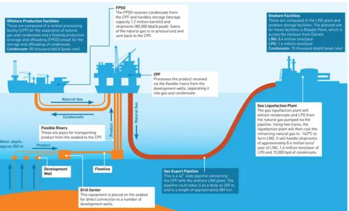
INPEX plans to install offshore a central processing facility (CPF) to develop the Ichthys field. The majority of the crude oil is transferred from the field through a subsurface transfer line to a nearby floating production, storage, and offloading (FPSO) facility where the condensate will be treated, stored, and offloaded to tankers for export. Natural gas from the field is sent through an 885-km-long gas export pipeline to the onshore facility at Blaydin Point in Darwin Harbour for processing of the gas into liquefied petroleum gas (LPG) and liquefied natural gas (LNG).
Figure 1: Schematic of the Ichthys LNG project 2.2 Ichthys FPSO
2.2.1 General description
There are two main trains in FPSO Ichthys, each capable of handling approximately 422 m3/h or
nominally 50% of the liquid production peak. Liquids reaching the FPSO though the subsea transfer line are received in the pipe slug catcher. The liquid is then divided equally between the two production trains. Each production train consists of three stages of three-phase separation: giving flash gas, condensate, and an aqueous stream.
The flash gas is compressed through a four-stage compression process. It provides gas to the FPSO, which is used by the gas turbine generators (GTG) to provide electricity to the whole facility. In the early life of the FPSO, there will be an excess of flash gas (in comparison with the needs of the GTG), and liquids from the intermediate pressure and medium pressure stages of compression will be sent back from the FPSO to the CPF via one of the flash gas subsea transfer lines.
-3-
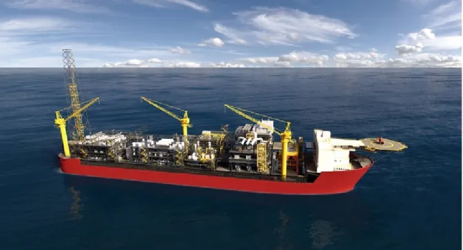
The condensate passes through three stages of separation. The condensate vapour pressure is controlled in a heating or cooling process during the final stage so that the condensate can pass straight from the final separation stage into the FPSO reception tanks. The reception tanks provide a final separation stage for the condensate. Any remaining rich monoethylene glycol (MEG) accumulates at the bottom of the tank and can be pumped out separately before the stabilized condensate is pumped into the cargo tanks. The condensate is transferred to storage at 48°C. The cargo tanks store the condensate at high temperate (38°C to 48°C) to prevent wax from dropping out. The contents of the cargo tanks are permanently running through heat exchangers located on the topsides to regain heat lost through the walls of the cargo tanks. The aqueous stream is called rich MEG (about 50%wt MEG in water). The rich MEG passes through a MEG regeneration unit, where MEG is recovered and re-concentrated to lean MEG (about 90%wt) for re-use.
Figure 2: 3D model of the FPSO
2.2.2 Heating and cooling requirements
Cooling requirement
The purpose of the cooling medium system is to facilitate cooling at certain stages of the process and remove excess heat generated by various items of equipment.
Closed loop re-circulating treated fresh water cooling systems is used throughout equipment packages. Cooling of the fluid medium will be via seawater system heat exchangers.
The cooling medium expansion tank shall be of sufficient capacity to provide a means of safely venting gas to flare in the event of gas cooler failure.
-4-
Heating requirement
A heating medium system is to be provided as a heat source for use in the gas and liquid hydrocarbon processing systems.
The system shall provide for:
• A closed loop system in which a suitable heating medium is constantly circulated;
• Heating medium circulation pumps with on line spares to assure power generation performance can be maintained at all times;
• Installation of a dump cooler to dissipate heat during low process heat demands; • A side stream filter arrangement to remove suspended particles.
The filter shall be of duplex construction to facilitate safe cleaning online. The design of the heating medium system will ensure maximum availability. There will be no single point failure mechanism within the system and all maintenance will be carried out while the system is on line.
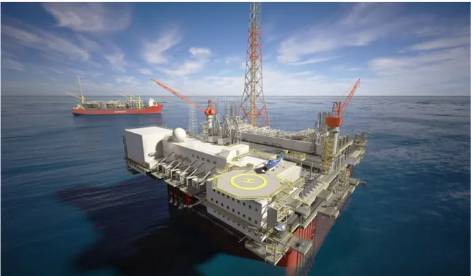
Figure 3: 3D-exploded view of the FPSO with the area of concern
2.3 Annex Installations
2.3.1 Subsea
Subsea wells are located in clusters (drill centres). Fluids are transported to the central processing facility (CPF) from the various drill centres through gas-gathering systems. Each gas-collection system consists of two flowlines connecting two to three drill centres to the CPF. At the CPF, each subsea flowline is connected to the topsides flowline with its own flexible production riser. The lean MEG (90%wt MEG in water) is injected in each well-head choke as an active hydrate inhibitor. This lean MEG injection results in the fluids arriving to the CPF being a mixture of gas
-5-
condensate, hydrocarbon gas, and a water/MEG mixture (rich MEG). The lean MEG is sent subsea from the FPSO.
2.3.2 CPF
There are three production trains on the CPF. Each of them has a nominal capacity of 600 MMscfd. Each flowline is connected to two of the three trains, but only one train at the time will be in line during operation. In normal production, there is basic gas or liquid separation in the ISV (inlet surge vessel). At the outlet of the ISV, the gas passes thought the high-pressure separator (which allows liquid drop-out) and then passes to the dehydration inlet scrubber. The flash gas that comes back from the FPSO is injected at this stage. The gas then passes through the glycol dehydration column in which the TEG (triethylene glycol) removes the water from the gas stream. The final stage has the export compressors leading the gas to the LNG plant through the gas export pipelines. After many years of field exploitation, the operating pressure of the ISV will be reduced. A booster compression facility will be inserted between the high-pressure separator and the dehydration inlet scrubber in order to ensure the operating pressure in the glycol dehydration column.
All the liquids removed during the different stages on the CPF are transferred to the FPSO through subsea transfer lines. In order to avoid the appearance of wax, the temperature of the transferred liquid is controlled in the liquid export heat exchanger. The gas or liquid separation in the ISV depends on the arrival temperatures of the fluids at the CPF. Higher temperatures will drive more gas out of the liquid, which means a reduction of the liquid flow to the FPSO.
Condensate is transferred from CPF to FPSO via one of the two condensate transfer lines. In normal operation, only one line is used at one time. However, under certain conditions, one line is not enough to support the flow rate, and both lines are used.
-6- 2.3.3 Gas Export Pipeline
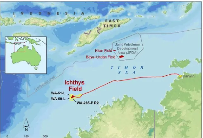
The dry export gas is fed from the topsides facilities of the CPF to the gas export riser base. The riser base provides a manifold connection of the four flexible risers and facilities for temporary connection of a subsea pig launcher. The gas export riser base is connected by rigid pipe to the gas export pipeline. Gas is exported via a nearly 900 km long pipeline from the CPF to the onshore LNG facilities located in Blaydin Point (Darwin, Australia). All along the pipeline, there are hot tap tees and a removable spool for future gas export pipeline tie-ins.
Figure 5: Localization of the Ichthys FPSO, CPF and the LNG facility connected by pipeline
2.3.4 LNG Plant
The facilities onshore at Blaydin Point, Darwin include gas receiving, an LNG process plant (2 x 4.2 Mtpa trains), product storage, and export facilities to LNG tankers. In addition to the production of LNG for the LNG tankers, other products that are produced and exported will include LPG and condensate.
-7-
3 THE COMPANIES
3.1 Client
Oil and gas projects no longer have only one client. In order to minimize risk for investment, the clients are usually joint venture holdings. The Ichthys project (FPSO, CPF, pipeline, LNG plant) is financed by INPEX (76%) and Total (24%). The client is named INPEX as it invests more. In this report, the term ‘client’ will be used.
Two major facts result from this joint venture holding. The first is due to Total. Total’s philosophy, named OPERCOMTM (explained in Section 5.1), is the conception philosophy used
for the Ichthys project. The second fact is that the Ichthys project is based in Australia. This leads to tougher regulations in design and commissioning.
INPEX Corporation is a global oil and gas exploration and production company headquartered in Tokyo. INPEX is involved in more than 70 projects in nearly 30 countries. In 2014, INPEX was ranked 61st in the global energy company ranking (see Platts Top 250).
Total is a global oil and gas exploration, production, and distribution company headquartered in Paris. It is involved in hundreds of projects in more than 130 countries. In 2014, Total was ranked eighth in the global energy company ranking (see Platts Top 250)
3.2 Constructor
Founded only 40 years ago, the DSME yard is now one of the top shipbuilding and marine engineering companies in the world. To give an example of its strength, in 2014, DSME became the first shipbuilder to receive an order for 49 gas carriers in a single year. The 4,900,000-m2 yard
employs more than 13,000 direct employees and 25,000 subcontracted production employees. The yard capacity is 55–60 commercial vessels, 16–18 offshore projects, and two to three special vessels.
From the 1970s to the current date, DSME has succeeded in major projects. DSME constructed 943 commercial ships (LNG and LPG carriers, oil tankers, full containership, etc.), and 439 offshore projects and plants (fixed platforms, FPSO, drillships, semi-submersible rigs, etc.).
-8- 3.3 Main equipment vendors
Sulzer (Pumps)
Sulzer is an industrial engineering and manufacturing company headquartered in Winterthur (Switzerland). It is one of the world leaders in the diesel pumps market.
LHE (Plate-type Heat Exchangers)
LHE is a local SME (small and medium-sized business) based in Busan (Korea). It produces heat exchangers for the naval industry.
Alfa Laval (Heaters)
Alfa Laval is an industrial engineering and manufacturing company headquartered in Lund (Sweden). It is a world leader in heat transfer, separation, and fluid handling.
General Electric (WHRU on GTG)
General Electric is a company headquartered in Fairfield (USA). General Electric is a global leader in the energy sector.
3.4 Sub-contractor for the Commissioning
Actemium is a subsidiary of the group VINCI Energies. It is the brand dedicated to the industrial process.
The commissioning activity of Actemium focuses on the OPERCOMTM philosophy and the
software ICAPS©. Actemium undertakes the following activities: • Delimitation of the systems and sub-systems
• Planning of the task, material, and equipment
• Organization of the different teams involved in the project (sub-contractors, suppliers, certification company)
• Human resources estimation
• Commissioning and pre-commissioning management • Population of the database in the software ICAPS©
Actemium provides commissioning on the following activities: administration and coordination ICAPS©, electricity, instrumentation, telecommunication, construction, mechanics, piping, and command control and process.
The main business sector of the commissioning activity of Actemium is the oil and gas sector (including exploration, production, refining, transport structure, compression station, and underground storage). The company is located in Europe (Norway, Spain, Italy, France, etc.), Africa (Gabon, Congo, Nigeria, etc.), the Middle East (Saudi Arabia, United Arab Emirates, etc.), Asia (Thailand, Indonesia, Korea, etc.), and America (Argentina).
3.5 Certification Company
DNV (Det Norske Veritas) is a Norwegian independent foundation that deals in risk management. It specializes in the evaluation and inspection of the technical conditions of naval construction. In this project, DNV is present to ensure that the engineering, construction, and commissioning is carried out safely and in the most efficient way.
-9-
4 THE INSTALLATION
4.1 Base of design
The installation is designed to produce 1,657 MMscfd (28,317 m3/day). Each day of unavailability
of the installation represents a significant daily shortfall. As the FPSO is located 300 km away from the nearest point on the Australian coast, the time needed to order, transport and install specific equipment (motors, heat exchangers, etc.) could stop production for weeks. In order to prevent any such shortfall, the redundancy philosophy is more exigent than in other industries. The security on the FPSO is another key point. Any system should be able to run at any time — even in case of equipment failure or during equipment maintenance. High pressure, high temperature, high voltage, high mechanical strain and toxic/ explosive/ flammable liquid and gas represent potential hazards. From the failure of an equipment may result consequential damages. Sparing and redundancy philosophy is thus based on these two main factors: shortfall and safety. The following are descriptions of all the equipment of heating and cooling systems, which are the subject of the sparing and redundancy philosophy. First, the sparing philosophy for each type of item present in the systems is described. Then, the sparing philosophy is explained for the instrumentation.
Note: When an item or instrument is indicated to be N+1 spared, it refers to N as the minimum number of items or instruments required for proper functioning.
Pressure Drums
Pressure drums are not susceptible to mechanical breakdown and as such do not require to be taken out of service frequently for maintenance or inspection purposes. Full field shutdowns will occur in year 1 and subsequently at 3 year intervals. The duration of full field shutdowns will vary depending on whether the shutdown is purely for inspection requirements or for planned maintenance.
Due to the requirement for total facilities shutdown to permit flare tip inspection and maintenance, most of the vessels within critical utilities systems are not spared. The cooling medium and heating medium expansion drums do not require to be spared. They will be inspected during this full facilities planned shutdown (every 3 years).
Shell & Tube Heat Exchangers
Shell and tube (S&T) heat exchangers are generally not susceptible to mechanical breakdown although appropriate protection shall be provided to safeguard equipment in the event of tube failure and cross contamination of fluids. In general, S&T heat exchangers shall not be spared and are inspected periodically.
However, the 2 x 100% heating medium exchangers (S-640-E-002-A/B) which supply heat to the secondary heating medium system are critical S&T heat exchangers. They shall be spared for productions reasons and for operation in fouling service requiring frequent maintenance for cleaning. For this reason, this heat exchanger is N+1 spared.
Air Cooled Heat Exchangers
Air cooled heat exchangers (ACHE) are susceptible to mechanical breakdown of the motor-driven fans.
-10-
However, an ACHE can continue to operate on reduced duty if a single fan is lost. ACHE are not normally spared, unless in a production critical service. The 2 x 100% heating medium dump coolers (S-640-E-001-A/B) are the only ACHE in a production critical service and are N+1 spared (although these ACHE are not normally in operation, one must always be available to remove residual heat from the WHRU when required).
Plate Heat Exchangers
Plate heat exchangers (PHE) are prone to leakage through gaskets and are more susceptible to fouling than S&T heat exchangers. Hence maintenance requirements are generally greater than for a S&T exchanger. In general, an N+1 sparing configuration shall be used.
PHE are used in heating and cooling medium systems. The FPSO seawater/cooling medium exchangers (S-650-E-001-A/B/C/D) are 4 x 33%.
Fired Heaters
Fired heaters are susceptible to mechanical breakdown and are generally spared for inspection and maintenance.
Fired heaters are required to make up the heating medium duty on the FPSO in addition to the heat supplied by the WHRU (S-640-F-001-A/B/C). Heating medium is a critical service, hence the fired heaters must have a high level of availability.
The heating medium fired heaters are to be marine ‘D’ type fired heaters. The optimum configuration for these heaters in terms of plot area, weight, cost and availability has been found to be 3 x 50% (S-640-A-002-A/B/C).
Initially the heating demand is less and the fired heaters will be a 3x100% installation; after year 5 of field exploitation the configuration will change to 3x50%.
Pumps
All types of pumps are considered to be susceptible to mechanical breakdown and generally shall have an installed spare. The decision not to install a spare will depend upon the criticality of the service and whether the pump is in continuous or intermittent operation. In general, pumps shall be N+1 spared.
The 3 x 50% heating medium circulation pumps (S-640-P-001-A/B/C), the 2 x 100% heating medium minimum flow pumps (S-640-P-002-A/B), the 2 x 100% secondary heating medium circulation pumps (S-640-P-010-A/B) and the 3 x 50% cooling medium pumps (S-650-P-001-A/B/C) are N+1 spared.
The 1 x100% heating medium top-up pump (S-640-P-003) is a specific exception. This pump only operates occasionally to top up the inventory of heating medium in accordance with the level in the expansion drum. Therefore a spare pump is not required.
Mechanical Filters
Mechanical filters generally operate in dirty services and require regular maintenance for flushing of filter elements, replacement of filter cartridges or removal and recharging of filter material. Filters are normally provided with installed spares to ensure that the process is not interrupted by the temporary unavailability of the filter.
In heating medium systems – where the temporary loss of a filter does not have a detrimental effect neither on the process nor on the environmental or safety implications – it can be chosen not to install a spare filter but to install a filter bypass instead.
-11-
Level gauges and transmitters (instrument)
In general, measuring elements (i.e. pressure, temperature, flow, level) are not required to be spared. A portion of the instruments are considered as “critical” instruments, where a failure of the instrument could directly lead to a system shutdown; these critical instruments are to be spared.
For the pressure and the level in the expansion drum of the cooling and heating systems, two measuring sensors and transmitters will measure the same process parameter, one for indication, control and pre-alarming and the other for tripping. Significant disagreement between the two transmitters (5%) will generate a discrepancy alarm. The level transmitter on the expansion drum will be spared (2 out of 3 voting).
Relief Valves (instrument)
Spare relief valves shall be installed where it is unacceptable for an item of equipment or system to be out of service for relief valve maintenance. In general, for every relief valve installation a spare relief valve shall be provided.
Emergency Shutdown Valves (instrument)
Emergency shutdown valves shall not be spared and shall be tested and maintained within planned shutdown periods as far as practicable. Annual emergency shutdown valve closure testing, and bi-annual leak testing will be done. If an emergency shutdown valve is taken out of service, the associated section of plant will be shut down.
4.2 Description of the System
4.2.1 Cooling Medium System
For a better comprehension of the system, appendix 1 shows the schematic representation of the cooling medium system and its major components.
The cooling medium system comprises of the following equipment items: - Cooling medium pumps, S-650-P-001-A/B/C
- Seawater/cooling medium exchangers, S-650-E-001-A/B/C/D - Cooling medium expansion drum, S-650-V-001
- Chemical injection eductor, S-650-M-001
3 x 50% cooling medium pumps, S-650-P-001-A/B/C, circulate the cooling medium via the 4 x 33% seawater/cooling medium exchangers, S-650-E-001-A/B/C/D. Each of the pumps is rated for 4146 m3/hr. From the plate exchangers, the cooling medium flows to the users.
Hot cooling medium from the users is collected and returned to the suction of the cooling medium pumps for recirculation.
The minimum ambient temperature in the Ichthys Field is 19°C and therefore the cooling medium can be inhibited fresh water. Fresh water will be dosed with inhibitor for the initial cooling medium system fill. Inhibition may be topped up by directly dosing the cooling medium expansion drum through the fresh water make-up nozzle, by temporary facilities. Chemical injection point for corrosion inhibitor and biocide is provided at the cooling medium pump suction line for batch injection of chemical when required. Biocide and corrosion inhibitor batch dosage rate is 250ppm and 500-1000ppm respectively.
-12-
The seawater/cooling medium exchangers, each rated for a duty of 74.6 MW, cool the cooling medium from 60ºC to 34ºC by heat exchanged with seawater. The seawater is supplied at a maximum temperature of 29ºC and heated to a maximum of 45ºC. The seawater flow is fixed. A constant cooling medium supply temperature is maintained by means of temperature control valves on the bypass line which control the cooling medium flow through and around the seawater/cooling medium exchangers.
Temperature control valves in the cooling medium outlet of each process user maintain the required process temperature by controlling the cooling medium flow through the cooler.
A bypass line with control valve is provided between the cooling medium supply and return distribution headers. A pressure differential controller, PDIC-024, detects the high differential pressure when the cooling medium demand depletes and will send signal to open the flow control valves to maintain closed loop flow. Dedicated low flow transmitter provided at each cooling medium pump discharge line will input to FIC-010. A low selector will compare input from PDIC-024 and FIC-010 and send signal to the flow control valve to ensure minimum flow of cooling medium pumps.
A cooling medium expansion drum, S-650-V-001, is installed at the highest point of the closed loop cooling medium circuit to allow for the expansion and contraction of the cooling medium at every start-up and shutdown. The drum is sized to sufficiently accommodate the required expansion volume.
Adequate net positive suction head for the cooling medium pumps is ensured by positioning the cooling medium expansion drum at the highest elevation and by a nitrogen gas blanket to the drum to maintain an operating pressure of 150 kPag. Any leakage of hydrocarbon gas into the cooling medium system will migrate to the system high point and be vented from the expansion drum to the HP Flare. The presence of hydrocarbons will be detected by an analyser on the vent line. A hydrocarbon analyser on the drum vent line continually monitors vented gas for hydrocarbon content which may arise from leakage within process coolers. High hydrocarbon concentration detected in the drum will alert operators.
The cooling medium circuit could experience some liquid losses and occasional make-up of the cooling medium inventory may be required from the service water system. Fresh water is added by flexible connection to the expansion drum.
The cooling medium system should be a clean system, however, to promote system cleanliness the strainer in each cooling medium pump suction line is a permanent installation. Corrosion inhibitor and biocide will be injected into the cooling medium system when required. Chemical drums and chemical injection inductor S-650-M-001 are provided for corrosion inhibitor and biocide injection.
4.2.2 Heating medium system
For a better comprehension of the system, appendices 2 & 3 show the schematic representation of the heating medium system with its major circuits and components.
The heating medium system comprises a primary and secondary circuit. The primary circuit provides the high temperatures required for the MEG regeneration package. A lower temperature secondary circuit is required for the liquid heaters, condensate heaters and cargo heat exchangers due to the risk of fouling at the higher temperature. The slop tanks heating coils could use the
-13-
primary heating circuit, but use secondary heating medium due to their location (near to the cargo heat exchangers) so that only one circuit is run to this location.
Both circuits have a pressurised expansion drum located at the highest point of the respective system, above all equipment in their circuit. Heating medium does not circulate through the expansion drums and is directly returned back to the pump suction manifolds. The heating medium return lines for each system are routed via a high point in their respective circuits, near the pump suction manifolds. The respective expansion drums are connected to the return lines at this high point to allow for free venting during the initial fill and removal of gaseous components which may be generated from breakdown of the water treatment chemicals during normal operation.
Primary Heating Medium Circuit
The primary circuit of the heating medium system comprises the following equipment items: - Heating medium expansion drum, S-640-V-001
- Heating medium circulation pumps, S-640-P-001-A/B/C - Heating medium minimum flow pumps, S-640-P-002-A/B - Waste heat recovery units, S-640-F-001-A/B/C
- Heating medium heater packages, S-640-A-002-A/B/C - Heating medium dump coolers, S-640-E-001-A/B - Heating medium exchangers, S-640-E-002-A/B - Heating medium filter, S-640-S-001
The heating duties of the following equipment are supplied by the primary circuit: - MEG reboilers within MEG regeneration package, S-730-A-001
- MEG recycle heaters within MEG regeneration package, S-730-A-001 - Rich MEG recycle heaters within MEG regeneration package, S-730-A-001 - Heating medium exchangers, S-640-E-002-A/B
The heating medium expansion drum is operated at a minimum of 2450 kPag to ensure an adequate margin above the maximum temperature in the circuit to prevent boiling in the WHRUs or in the additional combustion heaters. This pressure corresponds to a boiling temperature of 225°C (the chemicals inside the heating medium modify the boiling temperature of water), allowing a margin of 15°C above the maximum bulk fluid temperature of 210°C in the heating coils / tubes. This pressure is well above the pressure of the low pressure nitrogen distribution system and so is maintained from bottled nitrogen reserve within the nitrogen cylinder package. Post start-up there is minimal flow of nitrogen to the expansion drum with a tight regulation of the heating medium return temperature. For temperature excursions up to 190°C at the heating medium return header (which can only be precipitated by the sudden trip of at least two MEG reboilers) and without the benefit of any HP nitrogen make-up, the minimum pressure reached at the drum is expected to be marginally above the low pressure trip setting. However, if the primary heating medium circuit continues to cool without the nitrogen make-up, low pressure trip would eventually be triggered and the heating medium system would be unable to restart, until the drum blanketing pressure is re-established within the operating range.
Heating medium is circulated around the primary circuit via the heating medium circulation pumps. Discharge of the pumps is routed to the heating medium heater(s) and WHRU(s) in operation. All heat sources are operated in parallel. Normal operation will demand two out of three WHRUs in operation.
-14-
The heat available from the exhaust of the main power generation gas turbines will vary with the power demands on the FPSO and with the electrical power necessary to be exported to the CPF. The heating medium heater packages provide the balance of the heating duty for the heating medium system. A slipstream from the pumps discharge manifold is also routed to the heating medium filter to remove corrosion particles from the system.
Hot primary heating medium at normal supply temperature of 210°C is collected from the various heat sources and distributed to the users. The cooled (return line) primary heating medium is collected from the users and summed into the suction point of the circulating pump. For heat exchanger design purposes, the return temperature for maximum heat duty under fouled conditions is 160°C. Actual return temperatures will be lower during operation with clean exchangers and/or reduced throughput.
A hot bypass line across the supply and return headers is provided to pass the highest flow evaluated from the following criteria:
• Minimum required flow though a single heating medium heater plus a single WHRU; • Minimum required flow for one pump of S-640-P-001-A/B/C;
• Rated flow through one pump of S-640-P-002-A/B.
The heating medium minimum flow pumps are powered from the emergency switchboard and are continuously on standby with auto-start to provide back-up heating medium circulation to the WHRUs in the event of heating medium circulation pumps stoppage due to a trip or main power failure, in order to achieve a controlled shutdown and/or to sustain operation of any surviving main power generation gas turbines (without heat recovery).
Unlike the heating medium heaters, firing of the GTGs may not be stopped upon loss of main heating medium circulation. The heating medium minimum flow pumps ensure continued supply of a minimum heating medium flow to the WHRUs to remove residual heat gained from exhaust gas leaking through the dampers as well as heat from radiative transfer, in order to avoid exceeding the design temperature of the WHRU coils under pressurized conditions.
During main power failure or start-up of the heating medium system, no consumer is available for the heat absorbed from the WHRU; therefore the heating medium is routed to one of the dump coolers whose fans are also on the emergency switchboard, to reject the excess heat to the ambient air.
The primary heating medium circuit operates at pressures above that of the systems being heated and therefore exchanger failures will not release hydrocarbons into the heating medium circuit. Hydrocarbon detectors are therefore not provided for the primary circuit.
A corrosion probe, a corrosion coupon and a sample point are provided in the common heating medium circulation pump discharge header. A separate sampling point is also provided at the common inlet line to the shell side of the heating medium exchangers.
Secondary Circuit
The secondary circuit of the heating medium system comprises the following equipment items: - Secondary heating medium expansion drum, S-640-V-010
- Secondary heating medium circulation pumps, S-640-P-010-A/B - Heating medium exchangers, S-640-E-002-A/B
-15-
- Secondary heating medium filter, S-640-S-010
- The heating duties of the following equipment are supplied by the secondary circuit: - Liquid heater – train 1, S-211-E-001
- Liquid heater – train 2, S-212-E-001
- Condensate heaters – train 1, S-221-E-002-A/B - Condensate heaters – train 2, S-222-E-002-A/B - Cargo heat exchangers, S-241-E-001-A/B
- Heating coils in slop tanks, S-905-T-001 / 002 / 003
The secondary heating medium expansion drum is operated at a minimum of 240 kPag to ensure an adequate margin above the maximum temperature in the circuit to prevent boiling in the heating medium exchangers as well as to utilise the excess margin between operating and design pressure to improve the available net positive suction head in order to extend the life of the secondary heating medium circulation pumps. This pressure corresponds to a boiling temperature of 138°C (the chemicals inside the cooling medium change the boiling temperature of water), allowing a margin of 23°C above the maximum bulk fluid temperature of 115°C in the heating medium exchangers and provides a margin of 100% above the required net positive suction head. The nitrogen required for blanketing this drum is supplied from the low pressure nitrogen distribution system.
Heating medium is circulated via secondary heating medium circulation pumps. Discharge of the pumps is routed to the heating medium exchangers. There are no minimum flow pumps for the secondary circuit as the heating medium exchangers, being the only heat source, are non-fired heat exchangers and the colder tube side has been fully designed to withstand the design temperature of the hotter shell side. A slipstream from the main heating medium flow is routed to the secondary heating medium filter to remove corrosion products.
Hot secondary heating medium at normal supply temperature of 115°C is supplied to the users. The cooled secondary heating medium is collected from the users and returned to the pump suction. For heat exchanger design, the return temperature for maximum heat duty under fouled conditions is 95°C for the condensate heaters and liquid heaters and 90°C for the users in the hull, giving an average return temperature of 94°C. Actual return temperatures will be lower during operation with clean exchangers and/or reduced throughput.
The secondary heating medium circuit operates at a pressure lower than the liquid heaters. In case of tube rupture, hydrocarbons will be released into the heating medium circuit. Therefore, a hydrocarbon detector is provided for the secondary circuit at the secondary heating medium expansion drum.
A corrosion probe, a corrosion coupon and a sample point are provided in the common secondary heating medium circulation pump discharge header. A corrosion probe and a sampling point are also provided at the common outlet line from the tube side of the heating medium exchangers.
Top-up facilities
The top-up facilities for the heating medium system (primary and secondary) comprise the following equipment:
- Heating medium top-up tank, S-640-T-001 - Heating medium top-up pump, S-640-P-003
-16-
The heating medium top-up tank is an atmospheric tank. A connection is provided for filling the tank from the fresh water system. A DN300 diameter chemical measuring pot is provided to facilitate measurement of small chemical dosages involved during the routine top-up of corrosion inhibitor and oxygen scavenger, as well as contingent administration of scale inhibitor, in the event of hardness excursion in the fresh water supply. Topping up with make-up water and the addition of any chemicals are operated manually, with monitoring from liquid level instrumentation mounted near the operated valves, as well as from the control room.
Both primary and secondary circuits are topped up from the same tank and pump. The heating medium top-up pump suction is permanently connected to the heating medium top-up tank. The pump is a positive displacement type pump to suit the high pressure of the primary heating medium circuit. There is a hard-piped connection to both heating medium circuits.
Make-up water and top-up chemicals are added to the circuit at the circulation pump suction headers. A recirculation / mixing line is provided downstream of the pump discharge header on each circuit and routed into the expansion drum. It shall be opened manually for a short period of time after the addition of chemicals to allow the content of the drums to be homogenized with the circulation loop.
-17-
5 METHODOLOGY OF THE COMMISSIONING
Actemium has worked on many projects with Total. As this project is co-financed by Total and INPEX, the OPERCOMTM philosophy and its associated software ICAPS© have been used and
are therefore described here.
5.1 Methodology OPERCOMTM and ICAPS©
The OPERCOMTM philosophy was set up by Total in order to optimize - in terms of delay,
quality, and security - the transfer of a hydrocarbon exploitation structure from the construction team to the exploitation team. OPERCOMTM is composed of many specifications that summarize
Total’s conception of the commissioning activity. The goal is to define and prioritize the different installation activities, check and test all the equipment, and ensure traceability of these activities. These four specifications, which are applicable to all of Total’s projects, are the following:
• GS EP EXP 101: ‘Pre-commissioning and Commissioning Specification’. It defines how to successfully complete the pre-commissioning and commissioning activities. It explains the main definitions and characteristics of the tasks composing these activities.
• GS EP EXP 103: ‘Pre-commissioning and Commissioning Technical Preparation’. It details, in particular, the different documents to be produced for preparation of the pre-commissioning and pre-commissioning activities.
• GS EP EXP 105: ‘Pre-commissioning Execution’. It provides the information, procedures, and necessary support for the execution of the pre-commissioning.
• GS EP EXP 107: ‘Commissioning Execution’. It provides the information, procedures, and necessary support for the execution of the commissioning.
To support this OPERCOMTM methodology, the Total group developed the software ICAPS©.
This allows organization and monitoring of the preparation as well as execution of the different pre-commissioning and commissioning phases of an installation.
The various functionalities allowed by this software are: • Preparation of equipment list
• Preparation of the database of the task to be performed listed by equipment, sub-systems, etc.
• Generation of activity reports
• Management of the ‘punch list’ (see below) • Calculation of project progress
• Provision of a database for future maintenance of the installation
5.2 Project Organization
-18-
This division of activities saves a significant amount of time. As soon as the construction of one subsystem is completed (notably pipes installation, supports, equipment and wires), the pre-commissioning phase can start, even if the whole installation is not competed yet.
Figure 7: Comparison between normal project and a project under the OPERCOM philosophy
Similarly, this division enables carrying out the commissioning tasks of certain subsystems, whereas the construction and pre-commissioning of other subsystems is not completed yet (see Section 4.1)
According to OPERCOMTM, the division is as follows:
• Project: the whole installation (boat, platform, factory, etc.)
• System: subdivision of the project that performs a main function (electric generation, heating generation and distribution, water treatment, HVAC, etc.)
• Subsystem: subdivision of a system that performs a partial function of the system (waste heat recovery unit, produced water collection, ventilation for living quarters, etc.)
• Basic Function: group of equipment performing one elementary function (pump and its instrumentation, etc.)
• Item: equipment to check parts individually during the pre-commissioning execution (pump, fan, valve, transmitter, etc.)
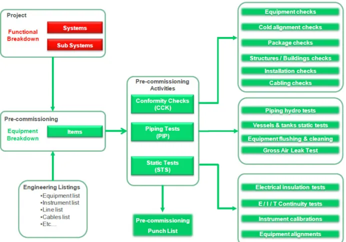
5.3 Pre-commissioning Activities
From a methodological point of view, pre-commissioning activity can be divided into three types of activity:
-19-
• Conformity Checks: These are conducted on each item in order to visually check the general condition of the equipment as well as its conformity with design project specifications.
• Static Tests: These are de-energized tests carried out on each item in order to check individual performance and quality (calibration of a transmitter, cables insulation, setting of a security pressure valve, etc.)
• Piping Tests: These tests are conducted on the piping and the vessels to check their mechanical integrity, cleanliness, and alignment (flushing, mechanical resistance test using water under pressure, chemical cleaning, leak test with air under low pressure). These tests are organized by ‘Test Pack’.
A ‘punch list’ is used throughout the project. It enables identifying all missing, incomplete or unsatisfactory documents and components. The punch list must be cleared before the beginning of the next phase.
An A-category punch list marks a major blocking point observed during the pre-commissioning activity. It prevents starting the commissioning of the considered subsystem (missing equipment, defective cable, etc.). It must be cleared before the signature of the ‘Ready for Commissioning’ certificate. This certificate validates the end of the pre-commissioning phase of the final installation.
-20- 5.4 “Commissioning” activities
From a methodological point of view, commissioning activity can be divided into four different types of activity.
• Preliminary Checks: These are carried out on each subsystem before the ‘Ready for Commissioning’ certificate is issued. It is a verification of the physical integrity of the subsystem, including also a review of the pre-commissioning dossier of the appropriate subsystem.
• Functional Tests: These energized tests are carried out on each electrical, instrumental or telecommunication basic function. This test proves the operability of the basic function according to the design criteria (e.g. proving the proper functioning of a pressure, temperature, or flow instrumentation). The electricity distribution readiness is a necessary condition to operate functional tests.
• Piping and Vessels Preparation: This activity is carried out on all the piping and the vessels in order to prove that they conform to specifications and are ready to receive the hydrocarbons (e.g. leak test, cleanliness of the pipes and the vessels, absence of oxygen, etc.). The typical activities are the following: drying, leak test with helium or nitrogen, reduction of the oxygen percentage, filling of the chemicals. These preparations are organized by ‘Test Pack’.
• Operational Tests: Operational tests are carried out on each sub-system in order to demonstrate that they are ready to operate as per the design. The tests confirm whether the sub-system is able to perform with nominal operational performance under proper security conditions. Inert fluid (water, nitrogen, air or diesel) is used to operate the subsystem during a significant period of time (from a few hours up to some days). The proper operation of the security systems is especially examined during this test (fire-water system, emergency stop of the installation under unsafe working conditions, gas emergency release, etc.)
This Master Thesis report is focused especially on operational tests, which are the most complex test procedures during the commissioning phase.
A B-category ‘Punch List’ marks a major blocking point observed during the commissioning activity. It prevents beginning the start-up operation of the considered subsystem.
-21- Figure 9: Summary of the commissioning activity
5.5 Start-up Activities
The ‘Ready for Start-up’ certificate issuance marks the end of the commissioning phase of a subsystem. It attests that all activities have been carried out properly and that the sub-system can operate.
The start-up activities correspond to the hydrocarbons introduction phase and the progressive deployment of the utility and process systems (electrical generation, lighting, service water, instrument air, etc.). It begins when all the required sub-systems are certified ‘Ready for Start-up’. It stops when all the equipment is working normally and in a stable way. After this phase, the installation can be transferred to the final Client for operation.
The Client and the contractor can agree to proceed to the commissioning phase off-shore with the introduction of hydrocarbons.
A C-category punch list marks a major blocking point that prevents the signature of the ‘Commissioning Completion’ certificate. This certificate marks the total responsibility transfer of the installation between the final Client and the contractor. These defaults are of secondary importance (painting work, non-essential documentation, etc.) but need to be cleared before the end of the project.
-22- 5.6 Engineering Documents
During the engineering phase, the contractor (or the company responsible for the engineering sub-contract) produces documents for the representation of the installation. Among these, the main documents are:
- Isometric Drawing: This is a scale drawing of the installation containing dimensions of the pipes, vessels, ship, equipment, etc.
- Process and Instrumentation Diagram (PID): This is a schematic representation of the pipes, vessels, pumps, process equipment, and all the instrumentation and control of the associated commands. Generally, a subsystem is represented by several PIDs.
- Process and Flow Diagram (PFD): This is a simplified diagram of the overall installation from a process viewpoint. Generally, a PFD represents an entire system.
- Single-line Diagram (SLD): This is an electric schematic representation using single-line representation. The whole electric installation of the site is represented using many SLDs. - Causes And Effects (CAE) Matrix: This is a double-entry table synthesizing the logic
functioning of the control system and security of the site.
- Data Document (DAT): This is a list of the specific data of certain equipment, such as dimension, power, intensity, noise, nominal flow rate, etc. Generally, these documents are supplied by the vendors.
PIDs are the documents that reference all the process equipment and their inter-connections. They gather all the necessary information for comprehension of the process on the installation:
- Circulation direction, and the type of the fluid
- Number, dimension, rate, and composition of the pipes
- Number, name, function, and main characteristic of the process equipment
- Number, function, set point of the instrumentation equipment, and their associated security (trigger point for the opening or closing of valves, alarm, shutdown of equipment, etc.)
-23-
5.7 Commissioning: Onshore and Offshore
The split of activities between those at shore and offshore can be summarized as follow:
• At shore: All utilities and process systems that do not require hydrocarbon to be commissioned and are not subject to offshore hook up will be fully commissioned before sail away. Other systems will be commissioned to the maximum possible extent.
• Offshore: All commissioning activities requiring hydrocarbon and/or offshore hook up will be completed offshore and subsequent systems commissioning will be completed.
The priorities are:
• To ensure that all works are carried out in a safe and efficient manner, safeguarding personnel and equipment with minimal impact on the regional environment;
• To maximise the amount of work completed Onshore, before Sail Away. This, in order to limit the project exposure to different or unknown/unsecure industrial environment and associated risks in terms of cost and schedule, and to minimize the duration of offshore commissioning and therefore the overall schedule;
• To ensure that all facilities meet their respective performance output rates as designed without any unplanned turndown or shutdown;
• To execute the Commissioning in a planned and controlled manner to bring the offshore facilities into service within time and budget;
• To demonstrate and put on record that all equipment has been tested according to the project specifications and best industry standards.
-24-
6 HEATING AND COOLING SYSTEMS OPERATIONAL TEST
PROCEDURES
6.1 General Planning
The FPSO Ichthys is divided into two main parts: the hull and the topsides. The hull is the first part to be constructed and tested. The cooling and heating systems both belong to the topsides. As the cooling medium system is required in all the subsystems including a pump with a cooling system, the construction of the M05 module for the cooling medium system is the first one. As a consequence, the cooling medium system is the first system to be tested during the topsides commissioning. The heating medium system will be used only during offshore operation. As a consequence, the heating medium system is one of the last systems to be tested. Both of the operational tests are initially planned to last five weeks.
6.2 Cooling System
Note: The figures in this section and the name tags for the cooling system components refer to the overall schematic of the cooling medium system shown in Appendix 1.
6.2.1 Activity completion
As mentioned in Section 5.4 (Commissioning Activities), before the operational tests can take place, conformity checks must be conducted. These checks ensure that all the pre-commissioning tasks (mentioned in Section 5.3. Pre-commissioning Activities) have been realized and the points in the A-category punch list have been cleared.
The functional test is necessary in order to ensure that all the instrumentation (pressure, temperature, level, noise or vibration indicators) are tested and calibrated. The alarms generated by the instrumentation are also tested. These tests are primordial, as the operational tests rely on the instrumentation.
Piping and vessel preparation is necessary in order to confirm that the system is able to support nominal pressure of 900kPa. The pressure test is realized by injecting nitrogen under pressure.
6.2.2 Pre-requirement of the OTP for the cooling medium system
Prior to commissioning, the availability of utilities such as instrument air, hydraulic power valve control system, power generation and distribution, and HP flare must be confirmed. Instrument air and hydraulic power valve control systems are among the first systems to be ready as they are required in almost all the systems. Similarly, power distribution is required in almost all the systems and is one of the first systems to be tested. However, power generation onboard, which is provided by a gas turbine, will not deliver any power during the onshore commissioning phase. The power is supplied by a temporary external power generator.
According to the construction and commissioning planning, the HP flare should be ready to use for the operational test of the cooling medium system. In case the commissioning of the HP flare is not finished yet, a temporary hose connection could be used to extract nitrogen to an appropriate and safe place.
The seawater system needs to be established prior to start-up of the cooling medium system. This system includes 3 x 33% seawater lift pumps, each pump having a design capacity of 4,740 m3/h.
-25-
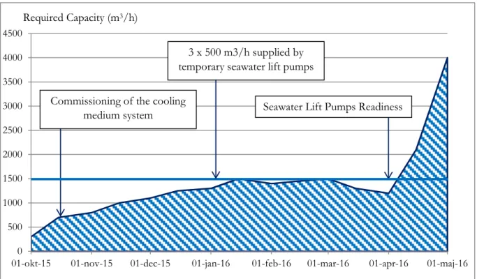
The cooling medium system is the main power user (90%). The seawater system will not be ready for this operational test. In order to avoid deformation of the heat exchangers structure due to lack of seawater under pressure, seawater must be provided during testing. Moreover, once the cooling medium system is ready, it will be used to cool other systems during their operational tests. Figure 9 shows the seawater requirement during the onshore commissioning phase. Before the seawater lift pump is ready, a flow rate of 1,500 m3/h is required. In order to provide this
flow rate, three temporary seawater lift pumps with a capacity of 500 m3/h will be used.
Figure 10: Seawater required capacity for operational tests
The service water system will not be ready. The cooling medium loops need to be filled with significant quantities of service water. The estimated required volume of service water is 500 m³. The filling of the loops will be done prior to the operational test conducted. Certified-quality water will be brought by tank lorries and transferred to the loops by temporary hose connection. Multiple filling points and venting points will be needed to remove the air from the cooling loops. The venting points are located close to the pumps and the heat exchangers. During the filling, the low-level alarms on the expansion drum will be dynamically tested.
The cooling medium loops should be injected with corrosion inhibitor and biocide to protect the system piping. The estimated required injection rate is 2,000L for the corrosion inhibitor and 150L for the biocide. If water were removed after the operational test, it would have been tested without the chemicals. The agreement with the client is that the water inside the cooling medium loops will not be removed after the operational test. But the chemical drums (for the corrosion inhibitor and the biocide) will not be ready for the cooling medium’s operational test. During the water filling of the cooling medium system, an appropriate dosage of corrosion inhibitor and biocide will be added. The dosage of chemicals will be determined by manual sampling along the cooling medium loop.
Once the cooling medium system is filled with water, the cooling medium expansion drum needs to be filled with nitrogen. The filling requirement is estimated to be 30 Sm³. Nitrogen will not be ready for commissioning of the cooling medium system. As the pressure required is only 600–800
0 500 1000 1500 2000 2500 3000 3500 4000 4500
01-okt-15 01-nov-15 01-dec-15 01-jan-16 01-feb-16 01-mar-16 01-apr-16 01-maj-16
Seawater Lift Pumps Readiness Required Capacity (m3/h)
Commissioning of the cooling medium system
3 x 500 m3/h supplied by temporary seawater lift pumps
-26-
kPa (in comparison with the heating medium system, which needs 2,600 kPa), the system can be pressurized with temporary compressors connected by a temporary hose connection. The pressure will be controlled on the discharge line of the compressors.
Note: The unit ‘Sm³’ is the standard cubic metre. It should not be confused with ‘Nm³’, which is the normal cubic metre. Both represent a gas volume unit. The reference conditions are the following: temperature of 0°C and pressure of 101,325 kPa for the normal cubic metre; and temperature of 15°C and pressure of 101,325 kPa for the standard cubic metre.
6.2.3 Control Philosophy
The objective of this OTP is to prove that the cooling system functions as per design, to ensure that all safety devices function as per design, and to check the function and operation of the equipment in different operating modes.
The safety devices must be tested during the operational test. Discussions between the client, the constructor, and the company in charge of commissioning led to the following agreement. Reaching a safety trip indicates that the system runs in a hazardous range of parameters. In case of failure of the trip, the test could damage the equipment. In order to prevent any damage, the safety device trip is tested by changing its setting point below/above the current value. Then, the initial setting point is re-instated.
This operational test must prove that the system functions as per design. The following equipment and their associated control need to be checked:
- Cooling medium expansion drum pressure control - Cooling medium pumps flow and pressure control - Cooling medium exchanger flow and temperature control - Cooling medium users temperature control
In the following sections, each piece of equipment and its instrumentation is described more specifically. The commissioning philosophy is to test each instrument by changing the set point (to a lower/higher value than the current one) and confirm the actions on the different equipment. In case the commissioning is done in another way, the philosophy will be mentioned.
6.2.3.1 Cooling Medium Expansion Drum S-650-V-001
Pressure Control:
Pressure in the cooling expansion drum is maintained by the presence of a pressurized nitrogen blanket. A constant pressure in the drum is achieved by pressure regulators in the nitrogen inlet and vent gas outlet lines, respectively. To minimize the consumption of high pressure nitrogen, the drum has 2x100% split range blanketing valves S-690-PCV-032-A/B on the drum overhead. Pressure fluctuation due to liquid level is allowed within the pressure band of 150 – 350 kPag. Outbreathing of the vapour is vented to the HP flare system via 2x100% split range pressure regulators S-690-PCV-028-A/B. The pressure is controlled in the drum to prevent reaching the boiling point of water. In case of a too high pressure in the tank, the PZHH trip will shut down the supply nitrogen valve S-690-SDV-031.
As mentioned in the paragraph 6.2.2 the nitrogen supply system will not be ready. Temporary air supply will be connected to both inlet (1) (refer to Figure 10) and outlet (2) of the pressure control
valve S-690-PCV-032-A. In order to avoid pressurizing the Expansion Drum above its design pressure, the valve before the inlet of the pressure control valve S-690-PCV-028-A (3) will be opened. First, air will be supplied by valves (2) and valve (3) will be closed progressively to test
-27-
the operation of pressure control valve S-690-PCV-028-A/B. Then, air will be supplied by valve (1) to test the operation of pressure control valve S-690-PCV-032-A/B.
Figure 11: Sketch of the cooling medium expansion drum and pumps
Level Control:
There is no automatic control on the drum level as it is sized for the maximum expansion of cooling medium from minimum ambient temperature of 19°C to maximum operating temperature of 80°C during turndown. The level rises and falls in accordance with the temperature of the system. At very low level values in the expansion drum (2 out-of 3 voting are provided for this LZLL to increase the reliability) the cooling medium pumps are instantly shut down. In addition, upon triggering high level, switch S-650-LSH-004-A will shut down the service water supply valve S-672-XV-001.
-28-
A switch is tested in the same way as a trip – by changing the set point below (for a high switch) or above (for a low switch) the current value. However it is interesting to explain the difference between a switch and a trip. A switch will start/stop a pump or open/close a valve. It changes the current state of the equipment. A trip will stop a pump or close a valve by forcing the equipment to go in its failure state and by inhibiting the equipment. A trip – contrary to the switch – will provide to re-start the pump or to re-open the valve. The operator will need to access the central security system to remove the inhibition.
6.2.3.2 Cooling Medium Pumps, S-650-P-001-A/B/C
Refer to Figure 10 and Appendix 1
Flow and Pressure Control:
The cooling medium pumps operate as 3 x 100% up to year 2, and as 3 x 50% for later years. The test will be done with the 3 x 100% configuration.
On failure of one of the operating pumps or low flow in the individual cooling medium pumps discharge, the standby pump will auto-start. The cooling medium pumps must be tested in full capacity to avoid high discharge pressure due to a lower flow rate.
The pump recycle flow line acts to prevent high differential pressure between the supply and return headers and to maintain the minimum flow. When the cooling medium demand depletes, there will be an increase in differential pressure across the supply and return headers. When the differential pressure exceeds the set point of 500 kPa, differential pressure indicator S-650-PDIC-024 will send signal to open the 2 x 100% recycle valve S-650-FV-010-A/B to maintain the closed loop flow.
Dedicated low flow controllers are provided for the cooling medium pumps - S-650-FI-257/258/259. The output from the flow controller of each pump is halved and summation of the outputs is used for modulating the recycle valve (each sized for minimum flow of two pumps). This output will override the signal from PDIC-024 and take control over FV-010-A/B.
In addition, dedicated low low-flow trip is provided for each pump which will cause a trip for the respective pump. However, if all operating pumps FZLL are triggered, this will initiate a production shutdown after a timer delay.
-29-
6.2.3.3 Cooling Medium Exchangers, S-650-E-001-A/B/C/D
Figure 12: Sketch of the seawater/cooling medium exchangers
Flow Control:
The seawater / cooling medium exchangers operate as 4 x 50% up to year 2, and as 4 x 33% for later years. The number of operating exchangers will be manually adjusted over the years of operation. During commissioning, the 4 x 50 % configuration will be tested.
The seawater flow need to be maintained at a constant rate through the seawater/ cooling medium exchangers independent of the cooling medium system cooling load. As mentioned in the paragraph 6.2.2, the seawater for the test will be supplied by temporary lift pumps.
Temperature Control:
At low cooling medium system loads, the temperature controller S-650-TIC-028 on the cooling medium supply header will detect low temperature and open the 2 x 100% control valve in the cooling medium bypass line around the seawater/ cooling medium exchangers, S-650-TV-028-A/B to control the supply temperature at 34°C. As none of the users will be ready for the operational test of the cooling medium, the temperature inside the cooling loop will not increase. The temperature control will be tested by reducing the temperature set point (as mentioned in section 6.2.3.).
Note 1: Pressure and temperature indicators belong to the seawater distribution system