Master of Science Thesis
KTH School of Industrial Engineering and Management Energy Technology EGI-2013-109MSC EKV973
Division of Applied Heat and Power Technology SE-100 44 STOCKHOLM
Fuel supply investigation for an
externally fired microturbine
based micro CHP system
Case study on a selected site in Bishoftu, Ethiopia
-2-
Master of Science Thesis EGI 2013: 109MSC EKV973
Fuel supply investigation for an externally fired microturbine based micro CHP system
Case study on a selected site in Bishoftu, Ethiopia
Aboma Emiru Aga
Approved
2013
Examiner
Prof: Torsten Fransson
Supervisor
Peter Hagström
Commissioner Contact person
Abstract
Sudden change on earth’s climate, which is a result of an increase in CO2 in the atmosphere, is mainly
caused by burning of fossil fuels for various energy services. However, for the energy services to be favourable to the environment, there should be a balance with the environmental protection, and we can call that “Sustainable Innovative Development”.
“EXPLORE Polygeneration” initiative will serve as an important tool to promote the application of renewable technologies extending to the future sustainable energy engineering field. This paper is intended in investigating a suitable fuel supply for the microturbine based micro CHP system available at the Division of Heat and Power Technology, KTH, Sweden; for a site called “Alema Farm PLC”, Bishoftu, Ethiopia.
Though there is a large biomass energy resource and a huge potential to produce hydroelectric power in Ethiopia, the modern energy sector is very small and the energy system is mainly characterized by biomass fuel supplies and household energy consumption. The nation’s limited biomass energy resource is believed to have been depleting at an increasingly faster rate.
Of the many and surplus amount of renewable energy resources available in and around Alema Farm PLC, poultry litter and pig’s manure are selected to be the two main energy sources for the CHP system available in the lab, after passing through different conversion techniques. However, after considering some basic properties like: Energy content and Bulk Density of the fuel, Moisture content , Ash characteristic, Tar content, Fuel logistics, Local storage, Fuel feeder system, and Magnitude of GHG Reduction; poultry litter is found to be the most convenient to produce a syngas with a Downdraft atmospheric gasifier available in the HPT lab.
Finally, For the problems caused by the nature of the poultry litter by itself and the methods used in the conversion process, the 40 TRIZ principles of TRIZ inventive principles is used and some major points are recommended.
-3-
TABLE OF CONTENT
1 INTRODUCTION ... 9 1.1 Objectives ...11 2 PERFORMANCE OF WORK ...12 3 MICRO-CHP SYSTEMS ...13 3.1 Microturbine ...13 3.1.1 Definition ... 13 3.1.2 Components of Microturbine ... 14 3.1.2.1 Combustor ... 14 3.1.2.2 Heat Exchanger ... 14 3.1.2.3 Turbocharger ... 15 3.1.2.4 Generator ... 15 3.1.2.5 Lubrication System ... 15 3.1.2.6 Recuperator ... 15 3.1.2.7 Atmospheric gasifier ... 16 3.1.3 Types of Microturbine ... 193.1.3.1 Externally or Indirectly fired Microturbine ... 19
3.1.3.2 Directly fired Microturbine ... 19
3.2 Sources of Energy for Microturbines ...20
3.2.1 Non-Renewable energy sources ... 20
3.2.2 Renewable energy sources... 21
3.2.2.1 Solar Energy ... 21
3.2.2.2 Biomass Energy ... 22
4 GENERAL COMPANY PROFILE ...30
4.1 Company overview ...30
4.2 Mission and Vision ...31
4.3 Products and Byproducts ...31
4.4 Energy supply and management ...32
4.5 The potential quantities in energy amounts of biomass and use ...34
4.6 The total supply of poultry litter, manure from cattle and pig and its use ...35
-4-
5.1 Introduction ...37
5.1.1 The Explore Vision ... 37
5.1.2 Explore polygeneration demonstration unit ... 37
5.1.2.1 Objectives ... 38
5.1.3 Approach ... 38
5.2 Biomass-Powered Gasturbine Based Ploygeneration ...39
5.2.1 Design ... 39
5.2.2 Fuel supply... 41
5.2.2.1 Biogas supply ... 41
5.2.2.2 Gas mixing panel from bottles ... 41
5.2.2.3 Downdraft atmospheric gasifier ... 42
5.2.2.4 Fluidized bed atmospheric gasifier ... 44
5.2.3 Prime mover – Compower Unit (CPU) ... 44
5.2.3.1 Fuel valve ... 45
5.2.3.2 Burner... 45
5.2.3.3 Control systems ... 46
5.2.4 Energy services ... 46
5.2.5 Connections, logistics and safety ... 46
5.2.5.1 Connection fuel source to prime mover ... 46
5.2.5.2 Connection prime mover to downstream services ... 46
5.2.5.3 Floor occupation and service availability ... 47
5.2.5.4 Safety procedures ... 47
5.2.6 System modeling and analysis ... 47
6 METHODOLOGY ...48
7 INVESTIGATION AND DETAILED STUDY OF FUEL SOURCES ...50
7.1 Introduction ...50
7.2 Syngas production ...50
7.2.1 Biomass gasifiers available in the laboratory ... 50
-5-
7.3 Production of syngas from poultry litter ...55
7.4 Alternative approach to energy generation from poultry litter ...57
7.4.1 Anaerobic digestion ... 57
7.5 Alternative approach to utilization of poultry litter ...58
7.6 Problems related to poultry litter gasification...58
7.7 Solutions for the problems related to poultry litter gasification ...59
8 CONCLUSION ...62
9 FUTURE WORK ...63
10 ACKNOWLEDGMENTS ...64
REFERENCES ...65
APPENDIX 1: LIST OF THE 39 TRIZ CONTRADICTION MATRIXES ...70
-6-
INDEX OF TABLES
Table 3.1: Typical physical characteristics of a Fixed Bed Gasifier (GasNet, 2010) ………...17
Table 3.2: Comparison of Fixed Bed Gasification Technologies (Naik-Dhungel, 2007)….………....………..17
Table 3.3: Typical Characteristics of a Fluidized Bed Gasifier (GasNet, 2010) ………..18
Table 3.4: Poultry litter analysis (New South Wales Department of Primary Industries, 2004)………...23
Table 3.5: Typical composition of biogas (Wikipedia, 2010d)………...…….…..……...25
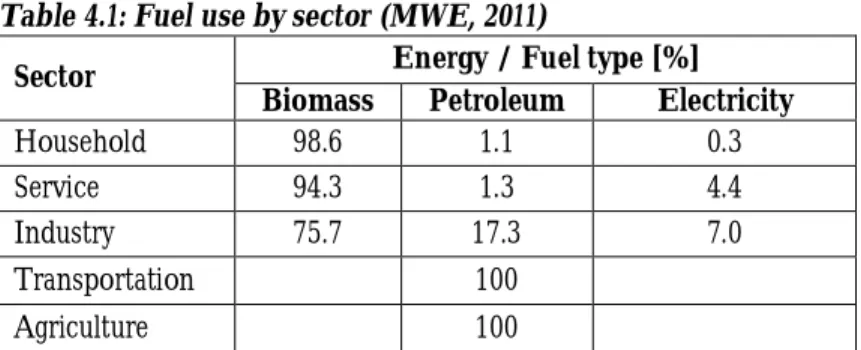
Table 4.1: Fuel use by sector (MWE, 2011)...33
Table 4.2: Energy resources potential of Ethiopia (MWE, 2011)...33
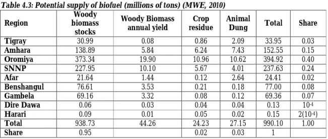
Table 4.3: Potential supply of biofuel in millions of tons (MWE, 2010)...35
Table 4.4: The approximate livestock number in the country (Central Statistical Agency, Agricultural Sample Survey 2010/2011) ……….………...36
Table 7.1: SWOT matrix for pig’s manure………..……...…………....…...54
-7-
INDEX OF FIGURES
Figure 3.1: Fixed Bed Gasifier Types (Bain, 2006) ………..…...………..……..16
Figure 3.2: Fluidized Bed Gasifier (Bain, 2006)……….18
Figure 3.3: The key process stages of anaerobic digestion (Wikipedia, 2010d) ………..…….25
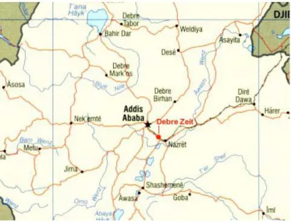
Figure 4.1: Location of the town Bishoftu (Debre Zeit) (Ethiopia guide, 2010) ………31
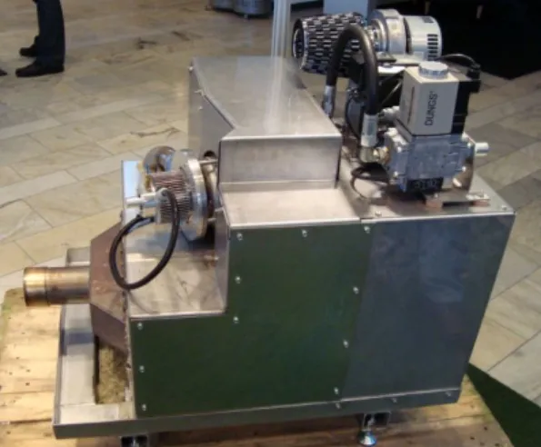
Figure 5.1: Gas turbine sub-system of the Compower CHP unit. This assembly includes the fuel valve, burner, primary heat exchanger, gas turbine and generator ………...39
Figure 5.2: The Micro CHP configuration ………..…………..……...40
Figure 5.3: Representation of the baseline configuration of the first Explore polygeneration demonstration facility, a biomass powered gas turbine with waste heat recovery. The gas mixing station will be design to allow the simulation of various biogas and gasified biomass mixtures ………....40
Figure 5.4: Downdraft atmospheric gasifier and its cleaning system in their current state of operation………..42
-8-
NOMENCLATURE
AC Alternate Current
CAD Computer-Aided Design
CHP Combined Heat and Power
EC Ethiopian Calendar
EEPCo Ethiopian Electric Power Corporation
EFGT Externally Fired Gas Turbine
GHG Greenhouse Gas
HPT Heat and Power Technology
HHV High Heating Value
ILRI International Livestock Research Institute
KTH Kungliga Tekniska högskolan
LHV Low Heating Value
LPG Liquefied Petroleum Gas
MWE Ministry of Water and Energy
NOAA National Oceanic and Atmospheric Administration's
NTP Normal Temperature and Pressure
PERC Propane Education and Research Council
PLC Private Limited Company
ppm Parts Per Million
STP Standard Temperature and Pressure
SWOT Strength-Weakness, Opportunities-Threats
TRIZ Teoriya Resheniya Izobretatelskikh Zadatch
TIPS Theory of Inventive Problem Solving
UN United Nation
UNDP United Nation Development program
-9-
1 INTRODUCTION
Economies can only survive in the long term if continuous innovative developments in every aspect are guaranteed. Increasing the innovative strength of every system is therefore vitally important. For this reason, out of the many other aspects, innovations in the stream of energy are becoming increasingly valuable, on a global manner.
As every move we make and every activity we do is related to our environment, one way or the other, with the innovative developments we are trying to bring, we put our environment at risk or favour. Meaning, the strategies we pursue, in order to bring the innovative developments we dreamed of, have a great effect on our environment.
The only way that our innovative developments could be favourable to the environment is; if we are trying to gratify our innovative developments without distressing the upcoming generation’s ability in every aspect, it could be resource utilization or environmental protection way. Therefore, we always have to try to bring a balance between our innovative developments and environmental protection, and we can call this “Sustainable Innovative Development”.
Sudden change on earth’s climate like; global warming, rapid melting of glaciers, rise of sea level, loss of
biodiversity, severe drought, cyclones and hurricanes are all results of an increase in CO2 in the
atmosphere. According to the National Oceanic and Atmospheric Administration's (NOAA) 2006 report,
CO2 concentrations in the atmosphere increased from approximately 280 ppm in pre-industrial times to
382 ppm, about a 36% increase in one and a half century. Relatively speaking, this may be a big change in
the history of the earth’s climate. This increase in CO2 emission is mainly caused by burning of fossil fuels
for various energy services used in the modern society. That is why; today our world needs a considerable revolution towards a Sustainable Innovative Development.
In addition to Sustainable Innovative Development, despite the varied and overall development and modernization strategies that have been pursued in the stream of energy, many energy transformation processes are still highly inefficient in the sense that they mostly concentrate upon one energy service, instead of using the available energy fully to supply different services at the same time.
“EXPLORE Polygeneration” is a wide project being held at KTH, at the Division of Heat and Power Technology. It is a stepwise growing demonstration case covering, from a system perspective, both the production and use of energy and all the dynamic relations in between. The concept of simultaneous transformation of basic energy sources through polygeneration is the next logical step to take towards a significant higher yield from the basic energy source. The multidimensional and interdisciplinary research and educational platform “EXPLORE", covers all major climate- and energy-related research in a global perspective.
Moreover, the “EXPLORE Polygeneration” initiative will serve as an important tool to promote the application of renewable technologies extending to the future sustainable energy engineering field by taking advantage of the facilities available at the Division of Heat and Power Technology (KTH/HPT). Therefore, “EXPLORE Polygeneration” is an excellent project, to resolve the mentioned two crucial problems, consequences of Innovative Developments in the stream of energy, sustainability and efficiency.
The microturbine available for this project is ET10, a microturbine based micro CHP system, available at the Division of Heat and Power Technology. The gas turbine system included in this system is based on a truck turbocharger and is externally fired from a burner that operates with atmospheric combustion. The residual heat is recovered by a large heat exchanger connected to a water circuit. Extensive electronics are implemented to monitor the system performance and a PLC with custom software is used to ensure smooth operation at 160,000 rpm. The whole assembly is fitted inside a standard, 2 m long container with theoretically the only connections required being fuel input, cold water input, hot water output and electricity network access.
-10-
“EXPLORE Polygeneration” comprises many Sub-systems and phases. Each of the sub-systems can be seen as work packages, with the workload further divided into work tasks addressing specific issues. These work tasks are then chopped into sub-projects sized to be suitable for MSc theses. Fuel supply investigation is one of the many work packages enclosed in this wide project called “EXPLORE Polygeneration, Work Package 19”.
The system, microturbine, was initially designed to operate on natural gas and, in the first phase, it has been tested for a fuel of biological origin, biogas. This gaseous fuel is supplied from pressurized cylinders and mixed using a series of flow controllers. At this stage, second phase, further refinement is going to be put on each of the sub-systems to allow the use of gasified biomass as an energy carrier. Thus, this work package, “Work Package 19”, is specifically aimed at investigating good ways to use locally available gasified biomass in an externally fired microturbine.
The availability, physical and chemical property of the gasified biomass to be used as an energy carrier depends on the nature of the specific place at which the study is to be held. In addition, I am a distance student doing this project from Ethiopia, on a distance basis. Therefore, in order to accomplish my study I have selected a specific place called “Alema Farm PLC”, Bishoftu, Ethiopia.
-11-
1.1 Objectives
As this work package is one part, sub-system, of the wide project “EXPLORE Polygeneration”, its general objective is to provide the required input to other work packages, like design, that uses the output of this project. This achievement modifies the gas turbine ET 10 to operate on gasified biomass, and use it as a prime mover for the production of electricity and recover waste heat to provide a variety of energy services.
The specific objective of this Work Package, “Fuel Supply investigation”, is to describe how the selected locally available gasified biomass can be fed into the combustion system of an externally fired microturbine, by taking into account the:
Fuel logistics, Local storage, Fuel feeder system, Combustor and
Composition of combustion gases in relation to heat exchangers and chimney downstream the combustion.
-12-
2 PERFORMANCE OF WORK
In order to achieve what is intended in the objective, here are some of the main activities that will be performed:
Gathering literature review about gasified biomass
Collecting all the necessary data about the selected geographical region of investigation Define one preferred fuel and one alternative fuel and describe why they are selected.
Describe the fuels with respect to available annual quantity, logistics, storage, combustion principles and composition of flue gas.
Define technical conflicts that must be avoided or accepted.
Using “theory of innovative problem solving” (TIPS, TRIZ) to propose work-around to these conflicts.
Compare solutions with respect to Strength-Weakness, Opportunities-Threats (SWOT)
Write a report describing the fuel supply in the selected region and the findings, technical conflicts and the proposed work-around, for the preferred fuel and the alternative fuel. Illustrate the results e.g. with statistics, price comparisons, photos etc.
-13-
3 MICRO-CHP SYSTEMS
For general application, energy appears in different forms. These forms typically include some combination of: heating, ventilation, and air conditioning, mechanical energy and electric power. Often, these forms of energy are produced by a heat engine. However, according to the second law of thermodynamics, heat engine’s maximum efficiency is limited by Carnot’s principle. It always produces a surplus of low-temperature heat which is commonly referred to as a "waste heat".
To make efficient use of energy, the "waste heat" must be used purposefully. And it can be put to a good use by a system called “Combined Heat and Power (CHP)” system or sometimes called “Cogeneration”. Micro-CHP system is an energy producing system involving the simultaneous generation of thermal (steam or hot water) energy between 3kW and 18 kW and electric energy between 1kW and 5kW by using a single primary heat source (Disenco Energy plc, 2006). By this way, Micro-CHP systems are able to increase the total energy utilization of primary energy sources. Most of the time, this system is used for home and small commercial building operations.
In traditional power plant, delivering electricity to consumers, about 30% of the heat content of the primary heat energy source reaches the consumer, although the efficiency can be 20% for very old plants
and 45% for newer gas plants.In contrast, a CHP system converts 15%–42% of the primary heat to
electricity, and most of the remaining heat is captured for hot water or space heating. Totally, as much as 90% of the heat from the primary energy source goes to useful purposes when heat production does not exceed the demand (Wikipedia, 2010a). However, when heat production exceeds the demand, a way to avoid it is to reduce the fuel input to the CHP plant. Moreover, CHP is most efficient when the heat can be used on site or very close to it.
Micro-CHP engine systems are currently based on several different technologies: Internal Combustion Engines
Stirling Engines Steam Engines Microturbines
3.1 Microturbine
3.1.1 Definition
A Microturbine is a gas turbine which incorporates all the components and represents all the characteristics of a gas turbine. It is becoming widespread for CHP application. And it is used for generating electricity, primarily, but having smaller power output when compared with a gas turbine. Typical microturbines produce between 30 kW and 250 kW of electric power (PERC, 2010). The exhaust heat from the microturbine can be used for water heating, space heating, drying processes or absorption chillers, which create cold for air conditioning from heat energy instead of electric energy, Microturbine-based CHP system. Microturbines can also be used in automotive applications such as buses. Moreover, microturbine is a recent development and is still being developed in many cases.
Microturbine operates with different fuels, but mostly with natural gases delivered at pressures exceeding 55 psi (379 kpa), may go as high as 90 psi (629 kpa), for driving the small turbine that powers the electric generator (Kolanowski, 2004). However, due to some reasons like: unstable natural gas prices, action toward carbon emissions regulation, and excess risk from dependence on a single fuel sources, we are forced to look for an alternatives (Capstone Turbine Corporation, 2010). An alternative fuel source, attractive from both environmental and economic perspective is a renewable fuel source, biomass. Though, biomass is a low-pressure gas, it can be boosted with centrifugal or scroll-type compressors and used (Kolanowski, 2004).
-14-
The electrical output of the microturbine is a high-frequency AC (1500–4000 Hz, 3-phase). The voltage is rectified and inverted to a normal 3-phase 50 or 60 Hz. Virtually, all microturbines are installed with recuperators to achieve 28–30% electric efficiency. Unrecuperated microturbines generally run at 14–17% efficiency (LHV) (Kolanowski, 2004). However, the efficiency of the microturbine can also be increased by utilizing the waste heat, either in a combined-cycle with a waste heat boiler and a steam turbine or in a combined-heat-and-power system, though; a further possibility is the recuperative air heating in the gas turbine itself.
Of the many others, one advantage of a microturbine is the ultra-low emissions that it emits. The disadvantage is that the small size of the compressor and turbine wheels limits the component efficiency, holds down the pressure ratio and prevents the turbine wheel from being internally cooled. Thus, the efficiency of a microturbine is well below that of a reciprocating engine, 14% vs. 40% (Kolanowski, 2004).
3.1.2 Components of Microturbine
A microturbine comprises components like: a combustion chamber (combustor), a heat exchanger, a turbocompressor (turbocharger), a generator and a lubrication system, with recuperator as an optional component. In addition, for biomass to be used as a fuel source, an integration of the microturbine with biomass gasifier, atmospheric gasifier, is required.
Here are some of the major components of a microturbine:
3.1.2.1 Combustor
A combustor or combustion chamber is one of the components of the microturbine, where combustion of the fuel-air mixture takes place to elevate the temperature of the exhaust air from the compressor, which finally expands in the turbine to drive the compressor and the electrical generator. The heat transfer, heating of the compressed exhaust air from the compressor, takes place through different mechanisms, accordingly with the type of the microturbine.
For a directly fired microturbine, the heat transfer takes place by burning the fuel with the compressed air in the combustor directly, the combustion gases are in direct contact with the moving parts of the machine. However, for an externally fired microturbine, the combustor is replaced by a heat exchanger and a burner; in case of using recuperation, the recuperator becomes part of the heat exchanger, the combustion gases do not pass through the moving parts of the machine (Kautz et al., 2009).
3.1.2.2 Heat Exchanger
The high temperature heat exchanger is the key to the success in the externally fired gas turbine. It is required to transfer heat from the heat source, combustion chamber, to the working fluid of the microturbine. The higher temperature the heat exchanger can provide the higher the system efficiency will be (Al-attaba et al., 2006).
Though, there are different types of heat exchangers, the main issue is how to build or select a heat exchanger that can withstand the stresses caused by the working conditions, considering a reasonable building cost. In addition, issues like: ability and ease of future expansion, Clean-ability, maintenance and repair and others are also considered.
With the nickel-based super alloys heat exchanger, the turbine inlet temperature could reach 800-825°C and in many projects they are using an additional natural gas combustor to raise the temperature up to around 1100°C to increase the cycle efficiency (Al-attaba et al., 2006). However, ceramic heat exchangers can reach such a high turbine inlet temperature with a long operational life time, but the production cost of these heat exchangers are very high which takes a very long payback time, but this option might be economical in the future with further developments for the ceramic heat exchangers technology to reduce
-15-
its costs (Al-attaba et al., 2006). We can calculate the power transferred to the air through the heat exchanger using the equation below:
Q = ma * Cp * (Δ Ta) (3.1)
3.1.2.3 Turbocharger
Turbocharger is a name given for a compressor and turbine mounted on a single shaft as an electrical generator. The main construction of the turbocharger is the impeller of turbine and the impeller of compressor which are placed on the same shaft, supported with two bearings. The compressor is taking the rotating torque from radial flow turbine which is placed in the exhaust of the engine, expanding the high speed exhaust gases. This main construction of the turbocharger is typically the same with the main construction of one shaft micro gas turbine, or we can call it the heart of the microturbine.
A truck turbocharger can be used to build a microturbine, for the advantage that a turbocharger is very cheap comparing with the microturbine engine.
In truck turbochargers, the compressor air pressure is about 3 bar absolute and the air flow rate is assumed to be low because the turbocharger is not expected to run in full speed, due to the low turbine inlet temperature, so air flow rate will be around 0.12 kg/s (Al-attaba et al., 2006).
3.1.2.4 Generator
Generator is a component of the microturbine that converts mechanical energy obtained from the rotating shaft of the turbine to electric current, usually by rotating a conductor in a magnetic field, thereby generating current through electromagnetic induction. This sort of generator produces an alternating current (AC).
Thought, generators are made in a wide range of sizes, from very small machines with a few watts of power output to very large central-station generators providing 1000 MW or more, generators used for microturbines typically produce between 30 kW and 250 kW of electrical power (PERC, 2010).
3.1.2.5 Lubrication System
Lubrication system is a secondary system used to lubricate and cool the turbocharger’s bearings. However, this doesn’t mean that it is not important. Our turbocharger depends totally on the lubrication system, because the rotating shaft is totally floating on the oil film which is also acting like a damping system to eliminate the vibrations. The modern microturbine engines are using air bearings with no oil.
The main components of the lubrication system are: High pressure automotive oil gear pump Driving electrical motor
Oil cooling unit. 3.1.2.6 Recuperator
The recuperator is a heat exchanger, transferring heat from the hot turbine exhaust gas to the colder compressed air in a heat exchanger between compressor and combustor. Almost all microturbines require recuperators to achieve desirable system thermodynamic efficiency. Before the compressed air enters the combustor, the exhaust gas is reduced to near compressor discharge temperature and the compressor discharge air is heated to near turbine exhaust gas temperature. The heat added to the compressed air reduces the amount of fuel required to raise the temperature to that required by the turbine and the thermal efficiency increases (Kolanowski, 2004). Recuperators are difficult to design and manufacture because they operate under high pressure and temperature differentials.
-16- 3.1.2.7 Atmospheric gasifier
While using biomass as a fuel source, an integration of the microturbine with biomass gasifier, atmospheric gasifier, is required. And the type of an atmospheric gasifier used varies with: the types of fuels, the efficiency level we want to operate in, expenses and others. Below, some of the gasifiers used are discussed.
Generally, two principal types of gasifiers have come into view, namely (Naik-Dhungel, 2007): Fixed Bed Gasifiers and
Fluidized Bed Gasifiers
Major characteristic of these gasifiers is discussed below:
Fixed Bed Gasifiers
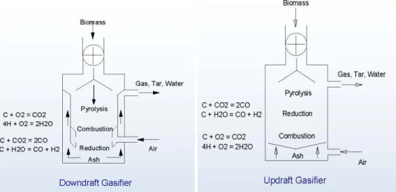
Fixed Bed Gasifiers typically have a fixed grate inside a refractory-lined shaft. The fresh biomass fuel is typically placed on top of the pile of fuel, char, and ash inside the gasifier. A further classification is based on the direction of air, oxygen, flows (Naik-Dhungel, 2007). Based on the direction of air flow, fixed bed gasifiers are classified as:
Downdraft Gasifier Updraft Gasifier and Crossflow Gasifier
In Downdraft Gasifier: air flows down through the bed and leaves as biogas under the grate. Whereas, in Updraft Gasifier: air flows up through the grate and biogas are collected above the bed and for the case of Crossflow Gasifier: air flows across the bed, exiting as biogas. Schematics of the primary section of the fixed bed gasifier types are shown in Figure 3.1.
Figure 3.1: Fixed Bed Gasifier Types (Bain, 2006)
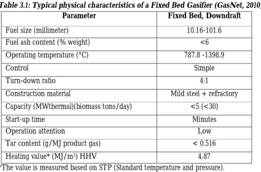
Fixed bed Gasifiers are usually limited in capacity, typically used for generation systems that are able to produce less than 5 MW (Naik-Dhungel, 2007). The physics of the refractory-lined shaft reactor vessel limits the diameter and thus the throughput. Though, developers have identified a good match between fixed bed gasifiers and small-scale distributed power generation equipment, the variable economics of biomass collection and feeding, coupled with the gasifier’s low efficiency, make the economic viability of the technology particularly site-specific. The typical physical characteristics of this Fixed Bed Gasifier are clearly shown in Table 3.1.
-17-
Table 3.1: Typical physical characteristics of a Fixed Bed Gasifier (GasNet, 2010)
Parameter Fixed Bed, Downdraft
Fuel size (millimeter) 10.16-101.6
Fuel ash content (% weight) <6
Operating temperature (°C) 787.8 -1398.9
Control Simple
Turn-down ratio 4:1
Construction material Mild steel + refractory
Capacity (MWthermal)(biomass tons/day) <5 (<30)
Start-up time Minutes
Operation attention Low
Tar content (g/MJ product gas) < 0.516
Heating value* (MJ/m3) HHV 4.87
*The value is measured based on STP (Standard temperature and pressure).
Due to the difference in the direction of air flow of the different types of Fixed Bed Gasifiers, their methods of operation differs too, and this results in different advantages and disadvantages. A major comparison between these different types of Fixed Bed Gasifiers is clearly shown in Table 3.2.
Table 3.2: Comparison of Fixed Bed Gasification Technologies (Naik-Dhungel, 2007) Types of Gasification
Downdraft Updraft Crossflow
Operation Biomass is introduced from the top and moves
downward. Oxidizer (air) is introduced at the top and flows downward. Syngas is extracted at the bottom at grate level.
Biomass is introduced from the top and moves
downward. Oxidizer is introduced at the bottom and flows upward. Some drying occurs. Syngas is extracted at the top.
Biomass is introduced from the top and moves
downward. Oxidizer is introduced at the bottom and flows across the bed. Syngas is extracted opposite the air nozzle at the grate.
Advantages Tars and particulate in the syngas are lower, allowing direct use in some engines without cleanup. The grate is not exposed to high
temperatures.
Can handle higher – moisture biomass. Higher temperatures can destroy some toxins and slag minerals and metals. Higher tar content adds to heating value.
Simplest of designs. Stronger circulation in the hot zone. Lower temperatures allow the use of less expensive
construction materials.
Disadvantages Biomass must be very dry (< 20% moisture content). The syngas is hot and must be cooled if compression or extensive cleanup is required. About 4 -7 % of the carbon is unconverted and remains in the ash.
Higher tar content can foul engines or compressors. The grate is exposed to high temperatures and must be cooled or otherwise protected.
More complicated to operate. Reported issues with slagging. High levels of carbon (33%) in the ash.
-18-
Fluidized Bed Gasifiers
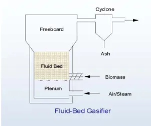
Fluidized bed gasifiers utilize the same gasification processes and offer higher performance than fixed bed systems, but with greater complexity and cost. Similar to fluidized bed boilers, the primary gasification process takes place in a bed of hot inert materials suspended by an upward motion of oxygen deprived gas. As the amount of gas is augmented to achieve greater throughput, the bed will begin to levitate and become fluidized. Sand or alumina is often used to further improve the heat transfer. Notable benefits of fluidized bed devices are their high productivity (per area of bed) and flexibility. Fluidized bed gasifiers can also handle a wider range of biomass feedstocks with moisture contents up to 30 % on average (Naik-Dhungel, 2007). The schematic of this Fluidized Bed Gasifier is shown in Figure 3.2.
Figure 3.2: Fluidized Bed Gasifier (Bain, 2006)
There are three stages of fluidization that can occur on the gasifier depending on the design: bubbling, recirculating, and entrained flow. At the lower end of fluidization, the bed expands and begins to act as a fluid. As the velocity is increased, the bed will begin to “bubble.” With a further increase in airflow, the bed material begins to lift off the bed. This material is typically separated in a cyclone and “recirculated” to the bed. With still higher velocities, the bed material is entrained. The typical physical characteristics of this Fluidized Bed Gasifier are clearly shown in Table 3.3.
Table 3.3: Typical Characteristics of a Fluidized Bed Gasifier (GasNet, 2010)
Parameter Fluidized Bed
Fuel size (millimeter) 0-20.32
Fuel ash content (% weight) <25
Operating temperature (°C) 732.2 -954.4
Control Average
Turn-down ratio 3
Construction material Heat-resistant steel
Capacity (MWthermal)(biomass tons/day) 5 and up(>30)
Start-up time Hours
Operation attention Average
Tar content (g/MJ product gas) < 0.86
Heating value* (MJ/m3) HHV 5.62
-19-
Generally speaking, Fixed Bed Gasifiers are typically simpler, less expensive, and produce a lower heat content syngas. Whereas, Fluidized Bed Gasifiers are more complicated, more expensive, and produce a syngas with a higher heating value (Naik-Dhungel, 2007).
3.1.3 Types of Microturbine
Based on the firing of the gas turbine, microturbine can be of two types. These two categories are: Externally or Indirectly fired Microturbine
Directly fired Microturbine
3.1.3.1 Externally or Indirectly fired Microturbine
The externally or indirectly firing of the gas turbine means that the combustion chamber is not directly connected to the gas turbine, therefore, the combustion exhausted gases are not inserted directly to the turbine and not in direct contact with the turbine’s impeller. Rather, the combustion process here is used for heating up a compressed fluid, commonly air, using a high temperature heat exchanger, and then the fluid is expanded in the turbine producing a high rotary speed shaft power (Al-attaba et al, 2006).
Both the indirectly and directly fired microturbines are similar in concept and both are explained thermodynamically by the Brayton cycle. In the indirect fired open Brayton cycle; first, the working fluid is drawn by the compressor and compressed. Then, the working fluid passes through a heat exchanger for heating up. After heating up, it expands through the turbine, and finally, either discharged directly to the environment from the turbine or returned back to the compressor after a cooling process (Al-attaba et al., 2006).
The externally fired gas turbine, EFGT, has the advantage of freedom in choosing the fuel source. The fuel sources could be liquid, gas or even solid types, like: coal and biomass fuels. Though, this advantage is also available in the Rankine steam cycle, the rankine steam cycle has a lower thermodynamic efficiency compared with the Brayton cycle which has a higher temperature of the working fluid in the inlet of the turbine with a lower pressure compared with steam temperature and pressure in Rankine cycle (Al-attaba et al., 2006).
The externally fired gas turbine cycle can be divided in to two types: The open cycle externally fired gas turbine.
The closed cycle externally fired gas turbine.
In the open cycle, the working fluid is discharged to the combustion chamber as a heat and oxygen supply for the combustion process, or discharged to the environment after decreasing its temperature in a heating or drying process. However, in the closed cycle, the working fluid is returned back to the compressor after a cooling process (Al-attaba et al., 2006).
3.1.3.2 Directly fired Microturbine
The direct fired gas turbine, DFGT, has a higher thermodynamic efficiency compared with the externally fired gas turbine because of the higher temperature of the combustion gases in the turbine’s inlet. However, on the other hand, direct fired gas turbine can only deal with the clean liquid or gas fuels along with the fuel compressing and injecting equipments which is not necessary in the externally fired gas turbine. The direct fired gas turbine can use the solid fuels like biomass or coal after gasification process only after an intensive cleaning process for the producer gas (Anheden, 2000).
Generally, in comparison with the directly fired gas turbine, the externally fired gas turbine sets less stringent requirements with respect to composition and cleaning of the combustion gas, as far as, the combustion gases do not pass through the turbine. In addition, EFGT also has the advantage of the preheated air, the utilization of the waste heat from the turbine in a recuperative process, and the advantage of allowing burning alternative, non-standard fuels, for instance biogenic fuels. The smaller unit
-20-
size also enables decentralized units appropriate for the biomass output from farms and agricultural processing units.
3.2 Sources of Energy for Microturbines
There are different sources of energy, source of fuel, for microturbine to drive the small turbine that powers the electric generator. Broadly, we can divide these energy sources in to two. These are:
Non-Renewable energy sources, and Renewable energy sources
3.2.1 Non-Renewable energy sources
Non-Renewable energy sources are sources of energy which are found naturally, not produced or generated by human beings (Wikipedia, 2010b). These energy sources have the highest consumption rate in our day to day activities. Most of our systems or machines today, industrialized society, are designed to fit for these energy sources, as well as microturbine. Quantitatively speaking, over 85% of the energy used in the world is from non-renewable sources (Connexions, 2009). Non-Renewable energy sources are also known for their higher heating values.
However, since these energy sources exist in a fixed amount and due to their high consumption rate, they are being consumed much faster than nature can create them and they also have higher environmental effect, climate change. From fuels that are grouped under this energy source, fossil fuels and nuclear power are the major ones.
Fossil fuels are compounds of the chemical elements carbon and hydrogen. Fossil fuels were formed millions of years ago, during the Carboniferous Period, from the remains of plants and animals. As the plants and animals that inhabited the swamps died, they were buried under sand and mud which stopped them from decaying. Over time, more sediment covered the remains and pressure, together with heat, turned them into natural gas, coal and oil deposits. These three are the main types of fossil fuels. However, there are also other like: oil shale and tar sands, but less-used. Fossil fuels are mostly found deep underground. Since the Industrial Revolution, we have come to rely on fossil fuels as our main source of energy. Today, fossil fuels are used in power stations to generate electricity.
Natural gas, one of the fossil fuels, is a gas that occurs naturally underground and piped to the surface through wells drilled into the underground rock. It is a mixture of gases, the most common being methane
(CH4) and it can be processed into propane and other types of fuels. It is usually not contaminated with
sulfur and is therefore the cleanest burning fossil fuel. All natural gas fuels are highly flammable and odorless, so for safety reason, natural gases are mixed with chemicals to give a noticeable smell before being sent to consumers. It can be stored and shipped in pressurized containers.
The use of natural gas is growing rapidly and is commonly used in homes to cook food and heat water, and compressed natural gas can power specially designed vehicles. Natural gas is the main energy source for microturbines. It can also be used as a source of hydrogen gas by reforming process.
The other fossil fuel is coal, which is a solid hydrocarbon that we excavate from underground, just as we mine for minerals. During the formation of coal, carbonaceous matter was first compressed into a spongy material called "peat," which is about 90% water (Connexions, 2009). As the peat became more deeply buried, the increased pressure and temperature turns it into coal. Coal is easy to transport, usually in large containers aboard ships or in special cars on trains. Coal is the most abundant fossil fuel in the world with an estimated reserve of one trillion metric tons.
Coal is mainly used for electricity production and sometimes for heating and cooking in less developed countries and in rural areas of developed countries. The burning of coal results in significant atmospheric pollution. The sulfur contained in coal forms sulfur dioxide when burned. Harmful nitrogen oxides, heavy metals, and carbon dioxide are also released into the air during coal burning. The harmful emissions can be reduced by installing scrubbers and electrostatic precipitators in the smokestacks of power plants.
-21-
The third one is oil, also known as petroleum or crude oil. It is a thick black liquid hydrocarbon found in reservoirs, hundreds to thousands of feet below the surface, and extracted by drilling wells deep into the underground rock and then inserting pipes. Once extracted, crude oil can be refined to various products. These include gasoline, diesel, jet fuel, home heating oil, asphalt, and oil burned for electrical power. Oil products are sent from refineries through pipelines directly to their consumers, or are delivered in large tanks aboard trains, trucks, or tanker ships.
Oil is the main source of power for vehicles, in the form of petrol or diesel. The burning of oil releases atmospheric pollutants such as sulfur dioxide, nitrogen oxides, carbon dioxide and carbon monoxide. These gases are smog-precursors that pollute the air and greenhouse gases that contribute to global warming. However, it is a preferred fuel source over coal. An equivalent amount of oil produces more kilowatts of energy than coal. It also burns cleaner, producing about 50 % less sulfur dioxide than coal (Connexions, 2009).
The other non-renewable source of energy is Nuclear power. Nuclear power originates from nuclear reactions which results in mass reduction that is converted to energy. Specifically speaking, from the atoms of the chemical element uranium, which is found in certain types of rock.
3.2.2 Renewable energy sources
Renewable energy sources are sources of energy that describe a wide range of naturally occurring, replenishable within a short period of time and infinite energy sources (Mourelatou, 2001). In its various forms, it derives directly from the sun, or from heat generated deep within the earth. Renewable energy sources include: Solar energy, Wind energy, Hydropower, as well as geothermal energy and energy from plants and animals, Biomass energy or biofuel. Though, there are many others like: Hydrogen and Ocean energy, the previous five are sources used most often.
In 2008, around 19% of the global total energy consumption was from renewable energy, with 13% coming from traditional biomass, mainly used for heating, and 3.2% from hydroelectricity. New renewable (small hydro, modern biomass, wind, solar, geothermal, and biofuels) accounted for another 2.7% and are growing very rapidly (Wikipedia, 2010c). Renewable energy sources are also seen as an alternative source of energy that are renewable, will never run out , and will not contribute to the climate change as that of non-renewable energy sources, produce little or no pollution or greenhouse gases. In other word, they overcome the problems of non-renewable energy.
Below, some of the most often used renewable energy sources are discussed clearly.
3.2.2.1 Solar Energy
The sun is our most powerful source of energy. It is a result of nuclear reaction called fusion. Sunlight, or solar energy, is commonly used for heating, lighting and cooling homes and other buildings, generating electricity, water heating, and a variety of industrial processes. It works by trapping the sun's rays into solar cells where this sunlight is then converted directly into electricity or hits solar thermal panels to convert sunlight to heat water or air (Orloff, 2010).
Most forms of renewable energy come either directly or indirectly from the sun. For example, heat from the sun causes the wind to blow, contributes to the growth of trees and other plants that are used for biomass energy, and plays an essential role in the cycle of evaporation and precipitation that makes hydropower possible. Therefore, we can say, solar energy is a starting point for other renewable energy sources too.
In addition to its renewability, it also doesn’t cause water or air pollution, because there is no chemical reaction from the combustion of fuels. However, it doesn’t produce energy at nighttime and cloudy days, as far as, the sun is not shining and it can be very expensive to construct (Orloff, 2010).
-22- 3.2.2.2 Biomass Energy
Biomass is the amount of organic material made from plants and animals and stores solar energy by the process of photosynthesis in the presence of sunlight. Plants absorb the sun's energy in a process called photosynthesis. The chemical energy in plants gets passed on to animals and people that eat them. So, in general term, the word biomass is used to describe all organic carbon-containing materials produced by photosynthesis in plants. Biomass is the only carbon source that is renewable and it can, directly or indirectly, be converted to biofuels of different forms. Therefore, Biomass Energy is the fuel energy that can be derived directly or indirectly from biological sources, biomass.
Biomass has been a major source of energy ever since people first began burning wood to cook food and warm themselves against the winter chill, prior to the discovery of fossil fuels like coal and petroleum. And wood is still the most common source of biomass energy. There are also other sources of biomass, like: food crops, grasses and other plants, agricultural and forestry waste and residue, organic components from municipal and industrial wastes, and even methane gas harvested from community landfills (West, 2010).
Generally speaking, biomass is a complex mixture that encompasses organic materials like: carbohydrates, fats, and proteins, along with small amounts of minerals, such as sodium, phosphorous, calcium, and iron. If we take plants as an example; the main components are carbohydrates, approximately 75% on dry weight, and lignin, approximately 25%, which can vary with plant type (Answers, 2010). The carbohydrates are mainly cellulose or hemicelluloses fibers, which impart strength to the plant structure, and lignin, which holds the fibers together. Some plants like: potatoes, sunflower, corn, and soybeans; also store starch and fats as sources of energy, mainly in seeds and roots (Answers, 2010).
Biomass derived fuels, biofuels, could be of solid, liquid, or gaseous forms. Liquid fuels can be used directly in the existing road, railroad, and aviation transportation network stock, as well as in engine and turbine electrical power generators. Solid and gaseous fuels can be used for the production of electrical power from purpose-designed direct or indirect turbine-equipped power plants.
Renewability and less environmental pollution are the major advantages of using biomass as a source of fuels or chemicals. However, difficulty of handling, less efficiency, larger area requirement and lack of portability for mobile engines are some of the major limitations of solid biomass fuels and to address these issues, research is being conducted to convert solid biomass into liquid and gaseous fuels (Answers, 2010).
A) Sources of Biomass Energy
Of its nature, biomass appears in two major forms: wet or dry. These two major forms of biomass have different sources. Though, wood is the most common source of biomass energy, especially in the developing countries, there are also other sources, from which biomass energy could be derived. The four distinct and common sources of biomass energy are:
Wood materials, includes: wood or bark, sawdust, timber slash, and mill scrap;
Energy crops, such as poplars, willows, switchgrass, alfalfa, prairie bluestem, corn (starch), and soybean (oil);
Municipal waste, such as waste paper and yard clippings; and
Agricultural wastes, such as corn stalks, straw, seed hulls, sugarcane leavings, bagasse, nutshells, and manure from cattle, poultry, and hogs.
Below, some of the sources of biomass energy are discussed in short:
Poultry Litter
Poultry, generally, stands for any domestic fowls, such as: meat chickens (broilers), egg laying chickens (layers), turkeys, ducks, geese, guinea fowls or pheasants; which are raised for their meat or eggs, primarily. All poultry ranks high nutritionally. It's classified as a complete protein, is a good source of calcium,
-23-
phosphorus and iron and contains riboflavin, thiamine and niacin. Poultry litter is a solid waste material discharged from the body of poultry, particularly feces. It is composed of undigested food, bacteria and water, and discharged from the body through the anus. In addition, it also contains feathers, and spilled feed.
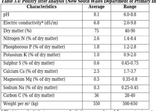
The chemical composition of litter is highly variable due to differing fowl species, diets, bedding retention times and other farm management practices. Below, a sample poultry litter analysis is shown in Table 3.4.
Table 3.4: Poultry litter analysis (New South Wales Department of Primary Industries, 2004)
Characteristics Average Range
pH 8.1 6.0-8.8
Electric conductivity* (dS/m) 6.8 2.0-9.8
Dry matter (%) 75 40-90
Nitrogen N (% of dry matter) 2.6 1.4-8.4
Phosphorous P (% of dry matter) 1.8 1.2-2.8
Potassium K (% of dry matter) 1.0 0.9-2.0
Sulphur S (% of dry matter) 0.6 0.45-0.75
Calcium Ca (% of dry matter) 2.5 1.7-3.7
Magnesium Mg (% of dry matter) 0.5 0.35-0.8
Sodium Na (% of dry matter) 0.3 0.25-0.45
Carbon C (% of dry matter) 36 28-40
Weight per m3 (kg) 550 500-650
* Electric conductivity is a measure of salinity, measured as a 1:5 suspension in water.
Traditionally, Poultry litter is used as a fertilizer. Comparing to other manures, the fertilizing value of poultry litter is excellent, but it is less concentrated than chemical fertilizers, giving it a relatively low value per ton. This makes it uneconomical to ship long distances. Instead, it is used on nearby farms. In addition, these days, it is also used as a livestock feed as a cost-saving measure compared with other feedstock materials, particularly for beef animals.
Though it is in smaller scale, some countries use poultry litter as a biomass energy source. They use the poultry litter as a fuel to heat the broiler houses for the next batch of poultry being grown thus removing the need for LPG gas or other fossil fuels. Some companies are also developing gasification technologies to utilize poultry litter as a fuel for electrical and heating applications, along with producing valuable by-products including activated carbons and fertilizers.
Manure from Cattle
The term manure from cattle is used to refer to excreta of cattle like: cows, sheep, pigs and others, and usually consisting of feces and urine; with or without litter such as straw, hay, or bedding. Because of its nitrogen, phosphate and other nutrients content, it has been used for centuries as a fertilizer for farming, as it improves the soil structure, aggregation, so that the soil holds more nutrients and water, and becomes more fertile. However, its composition varies greatly depending upon the animals that produce it. For instance, sheep manure is high in nitrogen and potash, and pig manure is relatively low in both. Often the manure is reinforced with additions of superphosphate to make it a better balanced fertilizer and to reduce the loss of nitrogen as ammonia.
-24-
Like poultry litters, manure from cattle could also be considered as a source for biomass energy. However, as manure from different cattle may have different qualities, physical and chemical properties, it should pass through different conversion technologies, so as to derive biofuels of different types and forms. Anaerobic digestion is considered as one of the most cost-effective alternatives for converting manure from cattle to biofuel. Especially, biogas plant processing swine manure have acted as an income source at the pig farms in some countries since it produces renewable energy (methane) and valuable digested residues that can be used as liquid fertilizer and soil conditioner.
B) Biomass Conversion Technologies
Biomass conversion refers to the process of converting biomass into energy that will in turn be used to generate electricity and/or heat or others too. As far as, biomass could be in dry or wet form. To use this biomass as an energy source, there are different routes to go through. Moreover, with today’s requirements for efficiencies, low cost, and low emissions, the conversion of biomass is in most cases still highly challenging. Therefore, the choice of conversion technology depends on the form that biomass appear in, property and quantity of the biomass, the desired form of the energy, environmental standards, economic conditions and project-specific factors.
For example, Dry biomass can be used as a fuel for gas turbines in different ways. It can be gasified or pyrolysed for internal combustion or it can be used as an external heat source. This heat source can be used to replace the combustor, to preheat the combustion air, or eventually to feed a primary reformer to yield hydrogen for the gas turbine (Ruyck et al., 2004). Wet biomass also goes under different energy conversion processes, to be used as an energy source.
The two principal technologies used to convert biomass into a usable fuel form, solid, liquid or gaseous, are: Biochemical conversion and Thermo-chemical conversion. Below, these two principal categories are discussed.
I. Biochemical Conversion
As far as biomass is a natural material, many highly efficient biochemical processes have been developed in nature to break down the molecules of which biomass is composed. And many of these biochemical conversion processes can be harnessed (Answers, 2010), so as to use biomass as an energy source.
Biochemical conversion is the transformation, breaking down, of biomass molecules through intermediates. These intermediates could be enzymes of bacteria or other microorganisms. In most cases, microorganisms are used to perform the conversion process. The major conversion techniques, grouped under this biochemical conversion are: Anaerobic digestion and Fermentation.
Anaerobic Digestion
Anaerobic Digestion is a biological process that occurs naturally when microorganisms break down biodegradable materials, organic materials, in the absence of oxygen (Wikipedia, 2010d). Almost any organic material can be processed with anaerobic digestion, including waste paper and cardboard, grass clippings, leftover food, industrial effluents, sewage and most of the time, animal wastes. The digestion process takes place in an airtight container, known as a digester.
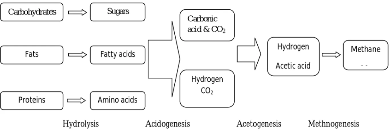
The digestion process begins with bacterial hydrolysis of the input materials in order to break down insoluble organic polymers such as carbohydrates into simple sugar, amino acids, and fatty acids, which make them available for other bacteria. Next, Acidogenic, fermentative, bacteria breakdown the remaining components further, i.e., the sugars and amino acids are converted into carbon dioxide, hydrogen, ammonia, and organic acid. In the third stage, acetogenic bacteria convert the resulting organic acids into acetic acid, along with additional ammonia, hydrogen, and carbon dioxide. Finally, methanogens convert
-25-
Hydrolysis Acidogenesis Acetogenesis Methnogenesis
Figure 3.3: The key process stages of anaerobic digestion (Wikipedia, 2010d)
There are three principal products of anaerobic digestion. These are: biogas, digestate and waste water (Wikipedia, 2010d). Biogas is the gaseous mixture obtained from this conversion technology, anaerobic digestion, and it can be used for energy generation since more than 85% of the potential oxidation energy of the organic substrate is retained in the biogas (Kheshgi, 2000). Though, the gaseous composition of biogas depends on the routes employed for the production and the type of biomass used, it is mainly composed of methane and carbon dioxide with a small amount of water vapor, hydrogen and trace hydrogen sulfide. The average values for these compositions are shown in Table 3.5.
Table 3.5: Typical composition of biogas (Wikipedia, 2010d)
Matter % Methane, CH4 50-75 Carbon dioxide, CO2 25-50 Nitrogen, N2 0-10 Hydrogen, H2 0-1 Hydrogen sulfide, H2S 0-3 Oxygen, O2 0-2
Most of the biogas is produced during the middle of the digestion, i.e., after the bacterial population has grown, and tapers off as the decayed material is exhausted. The gas produced by this process is normally stored on top of the digester in an inflatable gas bubble form or extracted and compressed in gas holder cylinders.
The methane constituted in the biogas can be burned to produce heat and/or electricity. The methane produced is usually used for a reciprocating engine or microturbine, and often, in a cogeneration arrangement where the electricity and waste heat generated are used to warm the digesters or to heat buildings (Wikipedia, 2010d). Excess electricity can be sold to suppliers or put into the local grid. Unless a leakage appears, Biogas does not contribute to the greenhouse gas (GHG) emissions to the atmosphere because the gas is not released directly into the atmosphere and the carbon dioxide produced comes from an organic source with a short carbon cycle (Wikipedia, 2010d). However, due to some other toxic products like hydrogen sulphide, it requires treatment or 'scrubbing' to refine it for use as a fuel.
Hydrogen sulphide is a toxic product formed from sulfates in the raw biomass and is released as a trace component of the biogas. National environmental enforcement agencies such as the U.S. Environmental Protection Agency or the English and Welsh Environment Agency put strict limits on the levels of gases
Fats Carbohydrates Proteins Sugars Hydrogen Acetic acid Hydrogen CO2 Methane CO Amino acids Carbonic acid & CO2 Fatty acids
-26-
containing hydrogen sulfide, and if the levels of hydrogen sulfide in the gas are high, gas scrubbing and cleaning equipment, such as amine gas treating, will be needed to process the biogas within regionally
accepted levels. An alternative method to this is by the addition of ferrous chloride FeCl2 to the digestion
tanks in order to inhibit hydrogen sulfide production (Wikipedia, 2010d).
The second output from anaerobic digestion is “Digestate”. It is the solid remnants of the original input material to the digesters that the microbes cannot use and also consists of the mineralized remains of the dead bacteria within the digesters. It can come in three forms: fibrous, liquor or a sludge-based combination of the two fractions (Wikipedia, 2010d).
Though, digestate typically contains elements such as lignin that cannot be broken down by the anaerobic microorganisms. It may also contain ammonia that is phytotoxic and will hamper the growth of plants if it is used as a soil improving material. For these two reasons maturation or composting stage may be employed after digestion (Wikipedia, 2010d).
The final output from anaerobic digestion systems is waste water. This water originates from the moisture content of the original waste that was treated and water produced during the microbial reactions in the digestion systems. This water may be released from the dewatering of the digestate or may be implicitly separate from the digestate (Wikipedia, 2010d).
The wastewater exiting the anaerobic digestion facility will typically have elevated levels of Biochemical Oxygen Demand and Chemical Oxygen Demand. Therefore, further treatment of the wastewater is often required. This treatment will typically be an oxidation stage where air is passed through the water in a sequencing batch reactors or reverse osmosis unit (Wikipedia, 2010d).
Fermentation
We know that, biomass is a mix of many organic materials like: carbohydrates, fats, proteins and other. For example, plants are composed of three basic components: lignin, cellulose and hemicelluloses. And lignin serves as a sort of “glue” giving structural strength for the biomass fibers. Hemicelluloses and cellulose polymers are the basic building blocks of the fibers. In order to breakdown the hemicelluloses and cellulose to sugars, the basic structural of the biomass must be attacked. Once the structure of the biomass is disrupted, the hemicelluloses and cellulose can be converted to sugars enzymatically (Agbontalor, 2007). And this is done by the help of the process called by fermentation.
Though fermentation has many definitions; fermentation under this concept is: a biochemical conversion, the breaking down, of the basic components of a biomass, specifically: hemicelluloses and cellulose polymers, into a relatively simple substance in order to release sugars, which can finally be used as a fuel source, in the absence of oxygen by the help of micro-organisms, that could be yeasts, bacteria or fungi (Agbontalor, 2007).
There are two basic approaches of biomass breakdown to sugars, fermentation. The first one is, acid hydrolysis with a variety of low acid-high temperature or high acid-low temperature conditions being suitable to both breakdown the structure of the biomass and release free sugars. And the second one is: enzymatic hydrolysis after some sort of pretreatment which allows enzymatic attack of the polymers (Agbontalor, 2007).
The acid hydrolysis is regarded as the most technologically mature method of sugar release from biomass. However, the second approach eliminates the need for large quantities of acid although, commercial cellulose enzyme costs are currently high and enzyme attack of the hemicelluloses and cellulose polymers can be slow (Agbontalor, 2007).
-27-
II. Thermo-chemical Conversion
Thermo-chemical conversion is the other principal technologies used to convert biomass, so as to use biomass as an energy source. It is a technology that transforms solid biomass to gas and then converted to biofuels, i.e., by breaking down the organic building blocks of biomass, partial oxidation, to carbon mono oxide and hydrogen gases. The major conversion techniques, grouped under this thermo-chemical conversion are: Combustion, Gasification and Pyrolysis.
Combustion
The most common utilization method of solid fuel biomass is direct combustion. It is employed, especially, in the developing countries where a bulk of biomass is used in unprocessed form by rural households in traditional and inefficient devices: for cooking, space heating and lighting (Agbontalor, 2007). The applications employed range from the three-stone fire to the sophisticated biomass burning boilers, which are used nowadays and known for their better efficiency and less emission. Generally, combustion can be defined as: an exothermic chemical reaction in which the biomass fuel is burned with excess air to produce a hot high-pressure steam that is used to generate power.
Today, a great effort at improving the efficiency of use of biomass as energy source, for this conversion method, is being employed. And the new technique discovered so far is called co-firing. It refers to the practice of introducing biomass as a supplementary energy source in high-efficiency boiler. A co-firing of biomass with other fuel can be advantageous with regard to cost, efficiency and emissions (Agbontalor, 2007).
Boilers today burn a variety of fuels and continue to play a major role in industrial process heating, commercial and institutional heating, and electricity generation. Boilers are differentiated by their configuration, size, and the quality of the steam or hot water produced.
Gasification
Biomass gasification is the other thermo-chemical conversion process. In this process, solid or liquid biomass is heated at high temperature, >700°C, with a controlled amount of oxygen and/or steam to
produce a low or medium calorific value gas, called synthesis gas or syngas. This gas has H2 and CO as
major constituents (Wikipedia, 2010e). However, the gas composition depends upon the starting moisture
content of the biomass raw material. In addition to the above mentioned gases, CO2 primarily, and some
low molecular weight alphatic hydrocarbons are also produced (Agbontalor, 2007). The heating value of syngas generally comes from CO and hydrogen produced by the gasification process. Depending on these carbon and hydrogen contents and the gasifier’s properties, the heating value of the syngas, can range
anywhere from 100 to 500 Btu/cubic foot (3.726 - 18.629 MJ/m3n) (10 to 50 % that of natural gas)
(Naik-Dhungel, 2007).
The gasification process includes several steps. The general process steps are (Wikipedia, 2010e):
1. Pyrolysis (or devolatilization): it is the primary conversion process where thermal decomposition of the biomass, in a controlled minimal amount or absence of oxygen environment, takes place to produce gases, liquids (tar), and char. Pyrolysis releases the volatile components of the biomass
feed at around 1100°F (593.33oC) through a series of complex reactions. Biomass fuels are an
ideal choice for pyrolysis because they have so many volatile components (70% to 85% on dry basis, compared to 30% for coal).
2. Combustion: this process occurs as the volatile products, the leftover tars and some of the char reacts with oxygen to form carbon dioxide and carbon monoxide, which provides heat for the subsequent gasification reactions. The basic chemical reaction is:
(3.2) Where letter “C” represents carbon containing organic compounds