V¨
aster˚
as, Sweden
Thesis for the Degree of Master of Science in Intelligent Embedded
Systems 30.0 credits
OBJECT DETECTION
Antonio Ezio Frascarelli
afi13002@student.mdh.se
Examiner: Giacomo Spampinato
M¨
alardalen University, V¨
aster˚
as, Sweden
Supervisor: Fredrik Ekstrand, Nesredin Mahmud
M¨
alardalen University, V¨
aster˚
as, Sweden
Company supervisor: Torbj¨
orn Martinsson
Volvo CE, Eskilstuna, Sweden
Acknowledgments
I would like to express my sincere gratitude to my colleagues and fellow labmates, Giulio and Giuseppina, for the time spent together, the sleepless nights and early waking, the stimulating discussions about theology and science and for the great fun we have had during these long 5 months.
A huge thank you goes to all the people I met during this two years experience here in Sweden, especially to Richi, Alma, Sejo, Carlos, Zohaib, Sama, Denis, Bruno, Cody, and Pavlosni.
To my parents, you are the only reason I reached this important goal. Grazie. Vi voglio bene. Last but not least, I would like to thank the love of my life, Sara, who has supported me during this long experience, continuously cheering me up despite all the difficult moments and the distance, and never giving up on me. Ti amo.
Abstract
During the last two decades the interest about computer vision raised steadily with multiple applica-tions in fields like medical care, automotive, entertainment, retail, industrial, and security. Object detection is part of the recognition problem, which is the most important scope of the computer vision environment.
The target of this thesis work is to analyse and propose a solution for object detection in a real time dynamic environment. RoboCup@Home will be the benchmarking event for this system, which will be equipped on a robot competing in the 2018 event. The system has to be robust and fast enough to allow the robot to react to each environment change in a reasonable amount of time.
The input hardware used to achieve such system comprise of a Microsoft Kinect, which provides an high definition camera and fast and reliable 3D scanner. Through the study and analysis of state-of-the-art algorithms regarding machine vision and object recognition, the more suitable ones have been tested to optimise the execution on the targeted hardware. Porting of the application to an embedded platform is discussed.
Table of Contents
1 Introduction 5
1.1 Computer Vision and Object Detection . . . 5
1.1.1 Object Detection . . . 5
1.2 Intelligent service robot . . . 6
1.3 RoboCup . . . 6
1.4 Problem Formulation . . . 7
1.5 Thesis outline . . . 7
2 Method 8 3 State-of-the-art: object detection algorithms 9 3.1 Local Features . . . 9
3.1.1 Key Point Detector . . . 9
3.1.2 Local Features Descriptor . . . 10
3.2 Feature Detection Techniques . . . 10
3.2.1 SIFT . . . 10
3.2.2 SURF . . . 11
3.3 Binary Descriptors . . . 13
3.3.1 BRISK . . . 14
3.3.2 FREAK . . . 15
4 Object Detection System Design and Development 17 4.1 Work environment . . . 17
4.2 Object detection in OpenCV . . . 17
4.3 Software Design . . . 17
4.4 SURF Detector . . . 22
4.5 Matching methods . . . 22
4.5.1 SURF . . . 23
4.5.2 BRISK, and FREAK . . . 23
4.6 False Positives Removal . . . 24
4.7 Position Estimation . . . 25
4.8 Speed-up Computation . . . 26
5 Test and Results 29 5.1 Testing the system . . . 29
5.2 Results considerations . . . 32
6 Future Work 33
7 Conclusion 34
References 36
List of Figures
1 System Development Research process. . . 8
2 Geometric transformations that must be handled by the key points detector. . . 9
3 Visualization of SIFT descriptor computation. Image Source: [7] . . . 11
4 SURF behavior with affine transformation on different angles (0◦, between 30◦and 60◦, and over 60◦). . . . 12
5 SIFT downsampling image pyramid (left) against SURF integral images with up-scaling filter (right). Image Source: [8] . . . 12
6 Gaussian approximation by box filter in SURF. Image Source: [8] . . . 12
7 SURF descriptor extraction. Image Source: J¨urgen Brauer [35] . . . 13
8 BRISK sampling pattern. Image Source: [16] . . . 14
9 Short distance pairs (512) on the left and long distance pairs (870) on the right. Image Source: [37] . . . 15
10 Receptive fields distribution over the retina in a human eye. Image Source: [15] . . 15
11 FREAK sampling pattern. Image Source: [15] . . . 16
12 FREAK’s sampling pairs resulting from Coarse-to-fine analysis. Image Source: [15] 16 13 Successful detection output from [Algorithm 4.1]. . . 18
14 Visual representation of descriptor containing local feature extracted from the same image using SURF (left), and BRISK (right). . . 20
15 Syntax of the “yml” file exported by the algorithm described in 4.3. . . 21
16 KeyPoints Grabber algorithm procedure . . . 21
17 OpenCV images coordinates management. . . 25
18 Object detection software visual output before[18a] and after [18b] the cropping procedure. [Blur has been added for privacy reasons]. . . 27
19 Objects used for testing . . . 29
20 Computational time (in milliseconds) test analysis. . . 30
21 Number of features detected in a frame. . . 30
22 Number of features matched between the frame and the object descriptor. . . 31
BRIEF Binary robust independent elementary features BRISK Binary robust invariant scalable keypoints CMOS Complementary metaloxidesemiconductor CPUs Central processing units
DSLR Digital single-lens reflex DoG Difference-of-Gaussian
FLANN Fast approximate nearest neighbor search library
FPS Frames per second
FREAK Fast retina key point GUI Graphical user interface
KB Kilo bytes
IFR International Federation of Robotics ISR Intelligent service robot
LoG Laplacian-of-Gaussian NSS Nearest neighbor search
OSs Operating systems
ORB Oriented FAST and rotated BRIEF
PCs Personal computers
RANSAC Random sample consensus SIFT Scale-invariant feature transform SURF Speeded-up robust features YAML Yet Another Markup Language
1
Introduction
The target of this thesis work is to analyse, and propose a solution for object detection in a real time dynamic environment, then the development of a vision system able to detect known objects. The overall requirement of the thesis work is object detection to fulfill high productivity, defined as relative execution time of a task when compared to a human, in a typical service tasks. The accuracy of the detection is taken into account as well as the time response of the system. The last is determined by the speed, calculated as Frames per second (FPS), at which the system is able to obtain images from the camera, and perform analysis on it.
The vision system achieved at the end of this thesis will be used as starting point for the devel-opment of an Intelligent service robot (ISR) [1] which will participate in the 2018 RoboCup@Home.
1.1
Computer Vision and Object Detection
Computer vision is that field of Artificial Intelligence that through acquisition of real world images, processing, analysis, and understanding aim to produce numerical or symbolic information in the form of decisions [2][3].
Applications for computer vision vary from industrial machine vision systems [4] to robots that can comprehend and interact with the world around them [5].
Computer Vision is a fast growing area of research thanks to increasing power of hardware and software. This is due the fact that optical object detection is a very challenging task since it has to deal with many problems at once: different views of an object, various light conditions, surface reflections, and camera noise are just some of them [6].
Scale-invariant feature transform (SIFT)[7] and Speeded-up robust features (SURF)[8], state-of-the-art feature detection algorithms, which will be described in section3.2, are able to partially solve these problems by computing image features, which are invariant anent scaling and rotation [9]. On the downside these algorithms are computational demanding and require powerful hard-ware to operate in real time [8]. For this reason the application, based on OpenCV[10], has been entirely developed using standard computer hardware. Its porting into an embedded platform is discussed in section6.
1.1.1 Object Detection
Since SIFT feature work by David Lowe [7], interest toward the area of feature detectors and descriptors has raised, encouraging more research about the subject.
The use of local invariant features facilitate the development of robust and efficient recognition proposals, which are able to achieve excellent results despite disadvantageous viewing conditions and partial occlusion.
The most used approach in the study of object detection is the use of image sets [11] to teach the system how an object looks like. These sets consists of a large number of views of the object from different perspectives [12], as the recognition must be invariant to view point changes such as rotation and scale [13], from which the system will extract relevant data.
The methods SIFT, SURF, and basically all the related algorithm derived by them, use to achieve object detection can be summarized into the following steps:
1. Find a set of distinctive key points.
3. Extract and normalise the previously detected region with regard to scale invariance and orientation.
4. Compute a descriptor from the normalised region. 5. Match the local descriptors.
During the first three phases some invariant features of each image in the object image set are selected. To do so, SURF combines a Hessian-Laplace region detector with its own gradient ori-entation based feature descriptor to discriminate among the features selection [8]. SIFT can use a combination of many region detectors1 achieving generally good performance [14].
The same analysis is then repeated on the analysed image, or video frame. In the next phase the obtained features are encoded in descriptors; such descriptors are then used in the upcoming matching where the two feature sets are confronted in order to get analogies. If any can be found, usually using a threshold of 5 or more correspondence, the object is detected in that scene.
As a features detector SURF is the most used solution, concerning detection of known ob-jects in a small and dynamic environment. Differently there are many valid solutions available to compute descriptors. A deeper analysis about two of them, Fast retina key point (FREAK)[15] and Binary robust invariant scalable keypoints (BRISK)[16], is described in details in chapter3.3.
1.2
Intelligent service robot
The International Federation of Robotics (IFR) has proposed a definition of a service robot: ”A service robot is a robot which operates semi or fully autonomously to perform services useful to the well being of humans and equipment, excluding manufacturing operations.” [17]
This definition is put in the framework of typical benchmarking events, such as the RoboCup@Home competition, which has defined several generic work tasks to be performed by autonomous robots. Productivity is seen as an overall measurement of performance speed that is believed to be an essential feature for any robot co-operating with humans in the context described above. An ISR that interacts with humans needs to be perceived as capable and easy to use [18]. If the robot is seen as a very slow partner, user acceptance quickly degrades.
1.3
RoboCup
RoboCup [19][20] is an annual global robotic competition for autonomous service robots aimed to foster AI and intelligent robotics by providing a series of different challenges. Many teams from different countries join the event challenging each other in five different competition2 each with a number of leagues. Each of this challenges focus on different aspects.
RoboCup@Home target is the development of a service robot which will be used for domestic applications. The robot capabilities are judged by its performance results in human robot interac-tion and cooperainterac-tion, navigainterac-tion and mapping in a realistic non standardized home environment, computer vision and object recognition and manipulation.
The task a robot must complete will range from registering itself for the competition, to per-forming service duty such as cleaning, or butlering for a previously unknown person, to grocery shopping in real world locations.
1Laplacian-of-Gaussian (LoG), Difference-of-Gaussian (DoG), Harris-Laplacian , Hessian-Laplace 2RoboCup Soccer, RoboCup Rescue, RoboCup@Home, RoboCup Logistics League, RoboCupJunior
1.4
Problem Formulation
The main challenge that an ISR has to face is the variable nature of the surrounding human envi-ronment while accomplishing both autonomous tasks and human guided tasks [21]. The ability to recognise and interface with objects is of primary importance.
Visual object recognition is a key function of the human brain. It tolerates fluctuations given by variable illumination and different viewing angles of the object [22]. The act of recognizing objects is a natural activity for humans as they possess a remarkable ability to determine what things are simply by looking at them [12]. Using prior knowledge, expectations and reasoning humans can effortlessly figure out objects they have knowledge of, and categorize unknown ones through knowledge fusion and exclusion, automatically weighting all the information given by visual inputs [23].
In computer vision, matching visual objects is challenging on a number of fronts. It is a very tough computational problem as each existing object can cast an infinite number of different images into a Complementary metaloxidesemiconductor (CMOS) image sensor3. This is due to the fact that it is not possible to represent all possible projections of an object, due to position, pose, lighting and background variations relative to the camera [24].
Despite years of research and experience, actual ISRs are still far from perfection. The ef-ficiency of ISRs participating to Robocup is arguable. The contestant fail when trying to detect objects and interface with them on the testing arena.
During the latest RoboCup Open, all the contenders showed big software issues. While ana-lyzing the surrounding environment, they failed the detection of objects positioned right in front of them often abending, showing lack of robustness, and spending a great amount of time computing. Those failures are oddly surprising considering the static nature of the environment setting, with artificial lights, blank backgrounds and lack of movements during object analysis.
This poor performance observed in ISR can be reduced if lower resolution is used to sense the external world. Lowering the working resolution does speedup the detection analysis. On the other hand, it reduce the sensibility of the system, constraining the detection to a closer range. The question which comes to mind is:
Main Research Question: “Is it possible to develop a vision system able to detect known objects at high frame rate, without sacrificing quality and distant detection? ”.
Using a higher resolution camera will allow the system to get a larger window view to the external environment, granting the possibility to enhance certain detail and get better results in terms of detection.
1.5
Thesis outline
This thesis is organized in the following sections: in section2 is presented the method used to carry out the thesis. In section3related works and algorithms used in the field of computer vision and object detection are presented and described. Section4 illustrate the software and different algorithms developed during this thesis work. In section 5 the experimental evaluation of the system is presented with a brief discussion on the result of the tests. Section6 gives a personal view on possible future work. Finally, in section 7 main ideas are summed up to give a brief explanation about the entire thesis work.
3Type of active pixel sensor made using the CMOS semiconductor process where circuitry next to each photo
2
Method
For this thesis work System Development Research [25] method has been chosen. This method is adopted when is hard to obtain a theoretical solution. As proposed by this method, a system has to be developed to prove that a given solution is valid to solve the proposed research question. This is done by evaluating the results obtained and, eventually, applying correction to the system.
As shown in figure1 the method consists of five phases.
Figure 1: System Development Research process.
In the first phase, a research question needs to be formulated. This question, as stated by Nunamaker and Chen [25], needs to be important in the applied field and clearly stated. The system functionalities need to be investigated together with the requirement. Existent and rele-vant literatures must be studied so that valuable information can be extracted and used to match the problem. Such literatures have been identified using manual research on two important dig-ital libraries, IEEE[26] and ACM[27]. This research helped to define state-of-the-art algorithms regarding object detection which are presented in section3.
In the second phase the system architecture must be defined with all the components and their interactions and functionalities. The fulfillment of the target objectives is predominant during the choice of constraints for the system components. Of course the system must be designed to be modular and easy to extend.
System analysis and design is done during the third phase. Here the functionalities to be im-plemented are driven by the project requirement and can be partially determined by the research sponsor request [25]. Alternative solutions need to be evaluated while one solution must be chosen and carried out.
The system is then built. Its implementation is the proof of the design feasibility and func-tionalities usability. During this phase the researcher can judge if the choice of framework and component has been appropriate. Such knowledge can be used to re-design or refine the system. Furthermore researchers gain insight about the problems and complexity of the system.
The last phase regards the evaluation of the system. It is observed by case study and evaluated by laboratory experiments. Purpose of these tests is to measure the performance and usability of the system, as stated in the requirement definition phase. Extensions can be developed as result of observation of the system’s usage.
3
State-of-the-art: object detection algorithms
Despite the fact that there are many different methods applicable to object detection to choose from, picking the most suitable and ensuring that it meets the application requirements can be very difficult.
The use of local features algorithms help to achieve object detection within the thesis require-ments. In the following sections will be explained in details the logic behind the state-of-the-art algorithms.
3.1
Local Features
Local features are the foundations on which this object detection work is built. The concept behind this is to describe a parsed image with a set of points, called key points or points of interest. Each key point can be described as an image pattern that diverges from its immediate neighborhood. This change is correlated to some image properties such colour, texture and intensity.
Thanks to these features the algorithms are able to identify local structures in the image and compute an encoded image invariant to translation, rotation, and scaling[28].
This extraction mechanism has to give the same feature as result of multiple iteration of the same object, given similar images.
Furthermore, features should be unique for each object to avoid misinterpretation with other image structures. Finally to detect a partially occluded object, an ample number of feature regions is needed to cover the target [28].
3.1.1 Key Point Detector
Depending on the nature of the viewpoint diversity expected for the target application, the op-portune detector must be chosen. The key points detected in a image must be the same in a geometrically transformed version of the latter and found in corresponding locations.
The detector needed for this thesis purpose has to be invariant to all kind of transformations like rotation, translation, scaling and affine transformations [Figure2].
Figure 2: Geometric transformations that must be handled by the key points detector. When dealing with larger viewpoint changes, as in dynamic environment matching applica-tions, affine invariance becomes paramount in order to still establish correspondences [29].
During RoboCup competition, ISRs are requested to recognise certain objects which are sit-uated in predefined places. The distance and movement speed at which the recognition must be executed is such that a scale invariant algorithm will suite perfectly without any substantial pre-cision loss.
3.1.2 Local Features Descriptor
After the detector has extracted interested points from an image, the region around those must be encoded in a feature descriptor or feature vector, which will be later used for discriminative matching [29].
The ideal descriptor captures the most important and distinctive information content enclosed in the detected salient regions, such that the same structure can be recognized if encountered [16]. Among the different existing approaches to describe the area surrounding a feature point, there are two main school of thought/denominations: local histograms based descriptors and binary descriptors.
The first category will be discussed together with their related detectors algorithms, while the seconds will be outlined afterwards.
3.2
Feature Detection Techniques
In this section the algorithms which were considered are described in details. First SIFT and SURF operation is illustrated. They provide both detector and descriptor functionality. Their performance can be extended with the use of other algorithms which adopt a different approach to achieve descriptors characterization.
3.2.1 SIFT
Presented in 2004 by Lowe [7], SIFT provides a great tool for extracting distinctive invariant fea-tures from images. It consists of four computation stages:
1. Scale-space extrema detection 2. Keypoint localization
3. Orientation assignment 4. Keypoint descriptor
The first phase uses a Difference-of-Gaussian (DoG)4 function to identify potential interest
points that are invariant to scale and orientation. Basically an image pyramid is built and each layer is filtered using a Gaussian.
In the second stage, a detailed model for each candidate is used to determine location and scale. Key points are selected based on measures of their stability: the ones which have low con-trast or are poorly localised on an edge are eliminated from the previously built list.
In the next step each key point is given a consistent orientation based on local image gradient directions. This is to achieve invariance to rotation, by delineating descriptors relative to key points orientation.
4Feature enhancement algorithm that involves the subtraction of one blurred version of an original image from
The same gradients are then used to create the key point descriptors. First they are rotated to line up with the key point orientation and then weighted by a Gaussian. A set of histograms are created using such data. The largest orientation values in the histogram are used as the main orientation of the feature descriptor [Figure3].
Figure 3: Visualization of SIFT descriptor computation. Image Source: [7]
At the end of the process, the original image data is transformed into scale-invariant coor-dinates relative to local features. For a 500x500 pixels image around 2000 stable features will be generated (depending on both image content and parameter choice)[7].
Despite being very good at matching locally affine pieces of images, SIFT is computation-ally expensive. Gaussian scale-space and gradient direction histogram computations take a large amount of time to be calculated.
3.2.2 SURF
The SURF algorithm, proposed by Bay and Tuytelaars [8] is based on the same principles as SIFT, but resorts to a different scheme and provides better results in a shorter time. As SIFT, SURF focus on scale and in-plane rotation invariant local features detection. It offers a good compromise between feature complexity and robustness to commonly occurring deformations [30]. SURF is not fully affine invariant as can be seen in figure4.
Skew, anisotropic scaling, and perspective effects are assumed to be second order effects, that are covered to some degree by the overall robustness of the algorithm. When the view angle falls under 60◦it displays partially invariant behavior to viewpoint changes. Raising the incidence angle over 60◦, SURF can match some features but not enough to detect the object.
SURF detection’s core is based on the determinant of the Hessian matrix5. Integral images
and approximated kernels are used to approximate and speedup the convolution, three times faster than DoG used in SIFT [31], which otherwise will be computational costly[8].
In SIFT, DoG is used to build up an image pyramid with different scales of the same image. In SURF different scales of Gaussian masks are used [Figure5] instead, keeping the image unaltered, saving time on the downsampling process [32].
The pyramid is then filtered using a box filter approximation of second-order Gaussian partial derivatives [Figure6], since integral images allow the computation of rectangular box filters in near constant time [8]. Essentially, Gaussian scale-space and the histograms of the gradient direction are replaced by fast approximations.
5Square matrix of second order partial derivatives of a scalar field, which describes the local curvature of a
Figure 4: SURF behavior with affine transformation on different angles (0◦, between 30◦and 60◦, and over 60◦).
Figure 5: SIFT downsampling image pyramid (left) against SURF integral images with upscaling filter (right). Image Source: [8]
The SURF descriptor uses Haar wavelets[33] to compute how the pixel intensities are dis-tributed within a scale dependent neighborhood of each interest point previously detected. The use of Haar wavelets increase robustness and decrease computation time [34].
A grid is built up around the feature point, split in 4 by 4 cells where Harr wavelets responses are computed at 5 by 5 regularly spaced sample points [Figure 7]. The absolute value of the response is summed, giving for each cell a 4 dimension descriptor vector, concatenated into a 64 dimensional vector.
Figure 7: SURF descriptor extraction. Image Source: J¨urgen Brauer [35]
3.3
Binary Descriptors
As explained in the previous section, SIFT and SURF are both efficient, especially the latter, and provide a good performance in detecting key point and extracting descriptors for each one. How-ever, they are based on gradient histograms where every single pixel need to be analysed, which costs computational time.
Despite the use of integral images adopted by SURF, some applications demand faster per-formances.
Binary descriptors provide the ability to encode all the information regarding the surrounding of a feature point as binary strings.
The limited memory demand while empowering faster computation, place binary key point descriptors as a great alternative to their competitors, especially during the development of appli-cations which target embedded vision.
Most recent binary descriptors consist of a sampling pattern, an orientation compensation method and a sampling pairs system. The pattern, which is distinctive for the chosen descriptor, is overlapped with the area around the detected key point and centered on it. Such sampling pattern is ideally a set of concentric circles.
A number of pairs of points is chosen on the pattern, and the intensity value of each point in the pair is compared with its matched one. If the first result is larger then the second, the value “1” is written in the string, “0” otherwise. When all the pairs have been analysed, the information describing the area around the key point will be encoded in a string of “0” and “1”.
The orientation compensation is a mechanism where the orientation of the interesting area is calculated relatively to some intrinsic feature of the area itself. The chosen pairs are rotated to that same angle, before evaluating the intensity, to make sure that the binary descriptor will result rotation invariant.
In the next sections two binary descriptors, which have been evaluated for this thesis purpose, are described to give a brief overview of their function. Despite being relatively new, BRISK and FREAK binary descriptors far surpass the industry standards as they perform much better than
the predecessor6 in this field [36].
3.3.1 BRISK
Taking in input a set of key points, the BRISK descriptor creates a binary string by concatenat-ing the results of intensity comparisons, as previously mentioned. In contrast with other binary descriptors7, BRISK adopts a custom sampling pattern where points lie on scaled concentric rings
[Figure8].
Figure 8: BRISK sampling pattern. Image Source: [16]
When the points are analysed, a small area around them, which radius is equal to the red circles shown in the pattern above, is taken and smoothed with Gaussian.
The BRISK algorithm defines the pairs in two subsets: short-distance-pairs, adopted to com-pute the intensity comparison necessary to assemble the descriptor, and long-distance-pairs, used to determine orientation [Figure9].
Short-distance-pairs consist of sampling points which distance is below a certain threshold ∆max. The distance of long-distance-pairs sampling points is above a certain threshold ∆min,
different from the previous one. The two thresholds are set as ∆max<∆min such as no
short-distance-pair is also a long-short-distance-pair.
The local gradients between long distance pairs are computed and the entire set is summed to estimate the feature orientation. Rotation invariance is obtained by rotating the short distance pairs at the same angle as the key point orientation [37]. For each pair the Gaussian smoothed intensity of one sampling point is compared with the other point of the pair. As said before, if the intensity is larger in the first point “1” is written as result, “0” otherwise. All this comparing will finally result in the binary descriptor [38].
Given a sample number of 60, the two subsets of distance pairing will count a total of 870 long and 512 short distance pairs. The descriptor will result 512 bits long.
6SIFT and SURF
Figure 9: Short distance pairs (512) on the left and long distance pairs (870) on the right. Image Source: [37]
3.3.2 FREAK
Similarly to BRISK, FREAK also makes use of a handcrafted sampling pattern. In their work Alahi et al [15] suggest the use of a pattern similar to the human retinal sampling grid [Figure10] where the density of receptive areas is higher in the center.
Figure 10: Receptive fields distribution over the retina in a human eye. Image Source: [15]
To mimic this behavior, a pattern where the points density drops exponentially with the distance from the center has been designed. Differently from BRISK the circles, or receptive fields, overlap while their size grows exponentially instead of gradually.
Each sample point needs to be smoothed to make it less sensitive to noise. The rings shown in figure11represent the standard deviation of the Gaussian kernel applied to the corresponding sampling point [15].
The overlapping introduce redundancy which adds more discriminative power to the algorithm allowing to reduce the number of receptive fields. The same redundancy exists in the receptive field of the retina, according to Tokutake et al. [39].
Computing the difference between pairs of key points areas and their respective Gaussian kernel, the descriptor is built as a string of one bit DoG. The matched pairs are selected differently from BRISK, which uses their spatial distance. In the used approach the best pairs are learned from training data, a coarse-to-fine[40] [Figure 12].
pat-Figure 11: FREAK sampling pattern. Image Source: [15]
tern. The inner ring is regularly left for the latest pairs. This is done similarly to the human eye, where the peripheral vision is used to estimate the location of an object of interest while the verification is achieved with the fovea area receptive fields [41].
Figure 12: FREAK’s sampling pairs resulting from Coarse-to-fine analysis. Image Source: [15]
FREAK orientation method, which compensate rotation changes, is similar to the one BRISK uses. Only 45 pairs are selected, with symmetric receptive fields with respect to the center. The higher number of receptive fields in the inner circle grants more errors handling than BRISK. This brings to a discretization of the space of orientation driving to a load of 5 times less memory [15].
4
Object Detection System Design and Development
4.1
Work environment
Vision algorithms are mostly developed on Personal computers (PCs) with general purpose Central processing units (CPUs) as they are normally easier to use compared to dedicated embedded hard-ware. There is a plethora of operating systems, tools and middle ware which can be used to achieve a working vision system which often uses complex, computationally demanding algorithms. Most embedded vision systems, and virtually all vision algorithms, begin life on a personal computer [23].
PCs are great platforms for research and prototyping as they are inexpensive and available everywhere. Outstanding development infrastructure are available for all the major PCs Operating systems (OSs). Generic software tools and libraries, vision specific libraries and design and simu-lation tools are free to use as well as an ever growing collection of example applications.
As the computational power of once weak devices keeps rising, smartphones and tablets have the potential to become effective embedded vision platforms[42].
For this thesis purpose an Intel CoreR TM i5 CPU powered PC equipped with 8GB of RAM,
has been configured to run the latest OpenCV libraries[43][10] taking advantages of the Microsoft Kinect[44] HD camera.
4.2
Object detection in OpenCV
OpenCV[43] is a free, open source BSD-licensed8computer vision software library originally
devel-oped by Intel, and now maintained by Willow Garage. It amounts to over two thousand algorithms, and can be installed on Windows, Linux, and Mac OS X. It is written in C++, and its interface is developed in the same language but is available an interface in Python; recently, new interfaces in Java, and MATLAB/OCTAVE have been developed.
Applications that are written using with OpenCV run on Microsoft OS, both PC, and Phone, Linux, Apple operating systems[45], android[46], Maemo[47], FreeBSD, and BlackBerry[48].
OpenCV is designed, and optimized for real time applications, dealing with fields such secu-rity, medical image processing [49], human-computer interaction, augmented reality, and robotics, among others.
OpenCV provides all the previously discussed algorithms to achieve object detection. Al-though, using them without knowing how they work, and how to set the dedicated parameters, will produce unexpected results with extremely poor performance.
4.3
Software Design
Once the environment had been set up [AppendixA], the first step to be done was to design the object detection software. The pseudo code in4.1shows a general idea of the first rough version
8BSD licenses are a family of permissive free software licenses, imposing minimal restrictions on the redistribution
of how the software was conceived. Pseudo Code 4.1: Object Detection v1
Data: x = (object template images enumerated from 0 to N)
1 for x ∈ N do
2 load x template image 3 image color preprocessing
4 detect image key points, and extract key points local features 5 store image local features in a descriptor
6 end
7 initialize camera, and set resolution 8 while escape key do
9 load camera f rame 10 f rame color preprocessing
11 detect f rame key points, and extract key points local features 12 store f rame local features in a descriptor
13 for x ∈ N do
14 if (image descriptor) match (f rame descriptor) then 15 extract object coordinate in f rame
16 show detected object [Figure13]
17 end
18 end 19 end
Figure 13: Successful detection output from [Algorithm4.1].
The basic idea was to have a certain amount of images representing the object to be found taken from different angles. Such images had to be stored in a certain folder, and named in a standard way, i.e. for the object “keso” the images had to be named keso 0, keso 1, keso 2, ..., keso n, so to be loaded trough a loop one by one in a Mat variable, which is the basic OpenCV image container.
As the image had to be computed by SURF to detect possible key points, it was loaded as a grayscale 8 bit image, as defined in [8]. This is due to a couple of reasons: first pattern matching has a better performance with using normalised grayscale images, coping better with different light conditions; second 8 bit dimension helps to avoid the curse of dimensionality[50]. Once the image was loaded, its key points were computed, and the local features extracted. Those information were stored in an array, to be used for the matching phase. This was done for all the object template
images9.
The next step was the camera initialization, and settings. In this stage of the software devel-opment the internal computer camera was still used. OpenCV provides a class for video capturing from video files or cameras, internal or external ones. Once the camera was initialised, single image frames were taken from it, then converted to 8 bit grayscale, and computed in order to extrapolate the local features.
To take advantage of the computer hardware the matching process was split in multiple threads, each one running on a single CPU core. The matching process was meant to take the local feature extracted from a single object template image, and try to match them with the ones found in the camera frame.
If a certain amount10 of matching features was found, a built-in method to extrapolate the
spatial location in the frame was used, and returned as 2D coordinates. This process, and the matching will be better illustrated in the next sections.
This preliminary version of the software could achieve object detection despite the computa-tional demand was considered excessive.
It required around 100ms for each template to be loaded, and its local features to be com-puted. To obtain a robust detection a picture from each angle of an object must be analysed. To obtain a more accurate result many images must be loaded, to the detriment of real time execu-tion. More images also meant more threads running the matching algorithm, which by itself took another 250ms for a single thread. All this resulted in a low frame rate (2 FPS).
The next implementation [Algorithm 4.2] aimed to take advantage of the BRISK descriptor to speed-up the computation.
Pseudo Code 4.2: Object Detection v2
Data: x = (object template images enumerated from 0 to N)
1 for x ∈ N do
2 load x template image 3 image color preprocessing
4 detect image key points, and extract key points local features 5 add image local features to image descriptor matrix
6 end
7 initialize camera, and set resolution 8 while escape key do
9 load camera f rame 10 f rame color preprocessing
11 detect f rame key points, and extract key points local features 12 store f rame local features into f rame descriptor matrix
13 if (image descriptor matrix) match (f rame descriptor matrix) then 14 calculate object coordinate in f rame
15 return object position 16 end
17 end
The use of binary descriptor allowed to get rid of the array used to store the descriptors related to each template image. In this new version the new extracted local features were “pushed” into a matrix file as a new binary string row.
This feature drastically reduce the memory usage. Furthermore, having all the features in a
9Pictures of the object to detect used as template to build detector, and descriptor.
single matrix, removed the need for matching the descriptors obtained from every object image with the one taken from the camera.
With this new solution the execution time was reduced by
n
X
i=1
(matching time)i | ∀ n ∈ template images set (1)
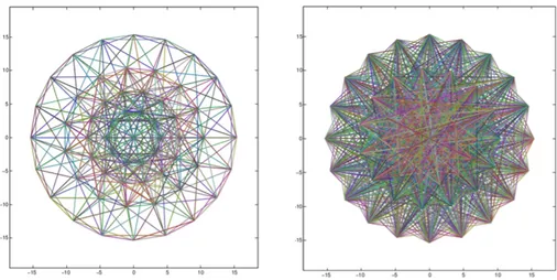
Figure 14: Visual representation of descriptor containing local feature extracted from the same image using SURF (left), and BRISK (right).
Aiming for robustness, having as reference a big number of images for object is paramount. In the latest revision of the developed software, additional improvements have been added. To take maximum advantage of binary descriptors another algorithm [4.3] has been created to take care of local features extraction.
Pseudo Code 4.3: KeyPoints Grabber
1 initialize camera, and set resolution 2 while escape key do
3 stream camera video 4 if (area is selected) then 5 area color preprocessing 6 extrapolate area dimension
7 if (area dimension) > (object dimension) then 8 object dimension = area dimension
9 end
10 detect area key points, and extract local features 11 store area key points into keypoint array 12 store area local features into descriptor matrix 13 end
14 end
15 export object dimension, keypoint array, descriptor matrix to file
This simple script allows the building of a file containing all the needed information for detect-ing an object. The produced output is a Yet Another Markup Language (YAML)’[51] file. YAML syntax [Figure 15] was designed to be easily mapped to data types common to most high-level languages constructs like lists, arrays, and matrices.
For this thesis purpose it has been set to export three fields, dim, keypoints, descriptors, de-fined by a known string so to ease the importing phase. The big advantage of using this system is
Figure 15: Syntax of the “yml” file exported by the algorithm described in 4.3.
the capacity of the object detection system to load all the needed informations, regarding a certain object, in a single step without the hassle of looping trough folder’s files.
An “.yml” file containing data of over 20 views of an object does not exceed the dimension of 400Kilo bytes (KB) while a single image used as training element accounts for the same dimension. It must also be considered that images to be used as template must be free of external visual references to avoid unrelated features to be detected. Pictures must be taken, cropped, and the eventual background removed before being parsed by the key points detection function. This new algorithm takes care of all the inconvenience [Figure16].
(a) Original image (b) Object area selection
(c) Image cropping
(d) Features extraction Figure 16: KeyPoints Grabber algorithm procedure
Pseudo Code 4.4: Object Detection v3
1 while escape key do
2 get object to detect name
3 load object dimensions, keypoint array, descriptor matrix from file 4 initialize camera, and set resolution
5 while escape key do 6 load camera f rame 7 f rame color preprocessing
8 detect f rame key points, and extract key points local features 9 store f rame local features into f rame descriptor matrix 10 if (descriptor matrix) match (f rame descriptor matrix) then 11 calculate object coordinate in f rame
12 return object position
13 end
14 end 15 end
4.4
SURF Detector
The detector algorithm choice fell on SURF. As has been touched on in the previous chapter, SURF detection algorithm uses a blob detector based on the Hessian matrix to find points of in-terest.
When declaring a SURF detector in OpenCV some parameters must be defined [1], as de-scribed in the algorithm documentation [52].
SURF( d o u b l e h e s s i a n T h r e s h o l d , i n t nOctave =4 , i n t n O c t a v e L a y e r s =2 , b o o l e x t e n d e d=t r u e , b o o l u p r i g h t= f a l s e )
Listing 1: SURF constructor
The “hessianThreshold” defines how large the output from the Hessian filter must be in order for a point to be used as an interest point. Giving a large value will give as result fewer but more salient interest points, while a lower value will result in more numerous but less salient points.
The second parameter depict the number of Gaussian pyramid octaves the detector will use. Giving as input a bigger value than the default, which is 4, will result in larger features.
The remaining variables are not mandatory to be set. They regard the number of images to be used within each octave of a Gaussian pyramid (nOctaveLayers) set by default to two, a flag(extended ) to set the computation of basic11or extended12 descriptor, and a flag to enable the computation of orientation features (upright ).
4.5
Matching methods
Depending on which descriptor algorithm is used to extract local features, a different matching procedure needs to be chosen. In the following section there is a brief description of how the differ-ent pairing algorithms are developed in relation of the descriptors tested during the developmdiffer-ent of this work.
1164 elements 12128 elements
4.5.1 SURF
SURF descriptor adopt the “FlannBasedMatcher ” interface in order to perform a quick, and effi-cient matching by using the Fast approximate nearest neighbor search library (FLANN).
FLANN is a library that contains a collection of algorithms optimized for fast nearest neigh-bor search in large datasets, and for high dimensional features [53].
The problem of Nearest neighbor search (NSS) is defined as follows: given a set of points in a metric space, they must be preprocessed in such a way that given a new query point, finding its nearest point in the previous metric space can be done quickly [54].
FLANN operating principle is quite easy to understand with an example. The FLANN matcher takes one feature from the object template descriptor, and looks for a nearest neigh-bor in the descriptor extracted from the image captured from the camera.
The method used in OpenCV to perform a matching using the FLANN matcher is shown in [2].
FlannBasedMatcher . match ( Mat queryImage , Mat t r a i n I m a g e , v e c t o r <DMatch> matches )
Listing 2: FLANN matcher method
The two matrices given as input are the object descriptor obtained from the template images, and the descriptor extracted from the camera image. The resulting vector “matches” contains the best match for each query key point, and its distance from it.
Once obtained a list of matches, the minimum distance between such key points must be calculated to collect only the “good” matches. Such are the ones whose distance is less than a certain threshold. This threshold is usually set as follows:
threshold = max(2 ∗ min dist, 0.02) (2) If a minimum of five good matches are found, the object is detected and its coordinates in the camera image can be calculated. This operation will be explained further on in this chapter.
4.5.2 BRISK, and FREAK
As binary visual descriptors, BRISK, and later FREAK were meant for fast matching, allowing tracking while the object was moving in front of the camera. Clearly they suit events where the object is still, and the camera is changing its position.
As said before, binary descriptors computation requires less resources in terms of calculation power, and memory to store the resulting feature points [55]. The matching phase provides another speed up if done using the Hamming distance.
The Hamming distance calculated between two binary string having the same length is the number of differing bits. The matching between two BRISK obtained descriptions can be achieved with a single instruction, the sum of the XOR operation between the two binary strings [56].
BFMatcher[57] is a descriptor matcher available in OpenCV which performs matching using the brute force method13. During its declaration [3] BFMatcher takes two optional parameters. The first refers to the distance measurement to be used while the second parameter is a boolean variable [59].
BFMatcher ( i n t normType=NORM L2, b o o l c r o s s C h e c k= f a l s e )
Listing 3: BFMatcher constructor
Hamming distance, NORM HAMMING, is used. The matching method adopted is the one showed in [4].
BFMatcher . knnMatch ( Mat queryImage , Mat t r a i n I m a g e , v e c t o r <v e c t o r <DMatch>> matches , i n t k )
Listing 4: knnMatch method
Given both the template, and the camera image descriptors as input the knnMatch function returns a vector containing the nearest neighbor matches. The “k” integer parameters is used to define how many match for feature must be returned.
After obtaining all the possible matches, and their neighbors, the list is slimmed down. This filtering is meant to remove unreliable matches.
4.6
False Positives Removal
During the matching phase, especially when operating in a dynamic environment, some features not belonging to the sought object can be confused for its own.
The matched features are used to estimate the position of the object in front of the camera. Wrong matching can lower the quality of the result reducing the accurate detection of the object. A method to assess false positive matches, and get rid of them has being developed using key points location estimation.
Each detected, and matched feature point has certain, and unique coordinates on the image matrix. The coordinates of the good matches are dumped into a Point2F vector, which is a tem-plate class for 2D points specified by its coordinates x, and y [60].
Such vector is then passed to the method 4.5 which will parse its content, and return only the key points belonging to the object.
Pseudo Code 4.5: FalsePositiveRemoval
1 determine key points average coordinate position
2 determine optimal distance from average key point position 3 for ∀ key point ∈ key point vector do
4 if keypoint is f ar f rom average then 5 remove key point from vector
6 end
7 end
In the first phase the average values of the x, and y coordinates of all the key points is cal-culated while the minimum, and maximum values are retrieved, and stored. These are needed in the second step to calculate the optimal distance, for both x, and y, from the average coordinates.
The optimal distance is calculated with a custom logic operation14[4.6].
Pseudo Code 4.6: Optimal distance algorithm
1 if (unsigned)(average − minimum) > (unsigned)(average − maximum) then 2 optimaldistance = (unsigned)(average − maximum)
3 else
4 optimaldistance = (unsigned)(average − minimum) 5 end
Once obtained the maximum distance from the average at which a point can reside without being considered a false positive, the removal function comes naturally as follow [4.7].
Pseudo Code 4.7: Key point removal logic
1 for ∀ key point ∈ key point vector do
2 if (key pointx > (averagex+ distancex)) || (key pointy > (averagey+ distancey)) || 3 (key pointy < (averagex< distancex)) || (key pointy < (averagey− distancey)) then 4 remove key point
5 end
6 end
4.7
Position Estimation
The graphical parameters of an object, and its position estimation in object detection problems is usually obtained computing the f indHomography method [5].
findHomography ( I n p u t A r r a y s r c P o i n t s , I n p u t A r r a y d s t P o i n t s , i n t method=0)
Listing 5: findHomography method
The first input parameter is a P oint2f type arrays containing the coordinates of the corner of the object to be found. Practically it keeps the dimensions of the template image, used to extract the local features, to be matched on the camera image.
The last parameter, used to describe which method should be used to compute the homog-raphy matrix, is usually associated with the Random sample consensus (RANSAC). This is an “iterative method to estimate parameters of a mathematical model from a set of observed data which contains outliers” [61].
The use of this method has been avoided for its request of object images. Such images need to be loaded to extrapolate the object shape, and would have overloaded the resulting software with useless information.
Needs to be mentioned that OpenCV coordinates are organised differently of a normal Carte-sian plan. As the images are considered matrices, the coordinates have to be considered as rows, and columns, as shown in figure17.
Figure 17: OpenCV images coordinates management.
The solution provided concerns the area around the object rather than the object shape itself. Using the vectorial sum of key points coordinates, the one situated closer to the matrix-axis origin
is taken as interesting area top-left point. In the same way the area width, and height is calculated using the object dimension loaded from file with the keypoint array, and descriptor matrix.
The algorithm [4.8] runs together with [4.7] as it requires the minimum, and maximum coor-dinates values to detect the area corners.
Pseudo Code 4.8: Object area detection logic
Data: minimum sum = (camera image width + camera image height), maximum sum = 0 origin cornerx, origin cornery, area width, area height, template width, template height 1 for ∀ key point ∈ key point vector do
2 if (key pointx + key pointy < minimum sum) then 3 minimum sum = key pointx + key pointy 4 origin cornerx = key pointx− template width 5 origin cornery = key pointy− template height
6 end
7 if (key pointx + key pointy > maximum sum) then 8 maximum sum = key pointx + key pointy
9 area width = key pointx − origin cornerx + template width 10 area height = key pointy − origin cornery + template height 11 end
12 if (origin cornerx + area width > maximum camera resolution) then 13 area width = maximum camera resolution − origin cornerx 14 end
15 if (origin cornery + area height > maximum camera resolution) then 16 area height = maximum camera resolution − origin cornery 17 end
18 end
A visual representation of the previous algorithm execution is shown in figure18.
With this information the camera orientation can be adjusted to direct the ISR straight to the localised target.
4.8
Speed-up Computation
The most computational demanding operation lie in the feature points extraction. The bigger the picture to analyse the longer the time taken. Parsing a full resolution camera frame, 1920x1080 pixels, and achieving object detection takes approximatively 800ms.
This result is achieved on a personal computer with large computational power. An eventual porting of the software on an embedded machine with limited resources, would result in extremely low performance.
Taking advantage of OpenCV image editing tools, the computation time can be drastically reduced. Once the object is detected, and its coordinates are extrapolated, the latter are used to isolate the object position in the next frame, cropping out the area around the object.
This saves the software to compute a large picture containing non interesting data, focusing all the resources on what is needed.
Cropping out a portion of the camera image results in better performance, once the object is detected. However, when the system is searching for it its reaction times are low.
(a) Original camera image
(b) Detected object in cropped camera im-age
Figure 18: Object detection software visual output before[18a] and after [18b] the cropping proce-dure. [Blur has been added for privacy reasons].
multi threading system to match multiple objects’ template images at the same time. To further speed up the performance a routine [4.9] has been added.
Pseudo Code 4.9: Camera Frame Crop
1 if (object not detected) then
2 crop camera f rame in four region
3 detect region key points, and extract key points local features 4 store region local features into region descriptor matrix 5 while (object not detected) do
6 if (object descriptor matrix) match (region descriptor matrix) then 7 calculate object coordinates in region
8 calculate object coordinates in camera f rame 9 return object position
10 end
11 end 12 end
In4.9 the camera image is divided in four quadrant. Each quadrant is processed to extract local features and matched with the object descriptor. This procedure is run in parallel as a single thread for each image region. If the object is detected its coordinates are calculated, so to crop its area and focus the detection process on it.
5
Test and Results
5.1
Testing the system
Some tests have been carried out to test the reliability of the resulting software using SURF as key point detector and BRISK as features extractor. The results shown below consist in the average of multiple tests executed during different days, under different lighting conditions which is common cause of failure among object detection systems.
Objects of common use or commonly present in home have been selected as test subjects. They are shown in figure19.
(a) Cheese box (b) Water bottle (c) Yogurt Figure 19: Objects used for testing
All the objects have been tested at different distances and in multiple stances: normally positioned, rotated 90 degrees and covered up to 50%.
The first test carried out was related to computational time for a successful detection. The first bar group shown in chart 20 refers to the instant when the object detection software was executed to detect the test subjects. The entire camera frame had to be analysed and matched with the object descriptor.
Once the object was detected, its position was extracted and the frame cropped around its area. This was reflected in the following test with a drop in computation time. This is better understood looking at the chart in chart21. Here is shows how many features point the software detected in each testing condition. In the first frame, the entire image taken from the camera is analysed, giving as result thousand of key points.
In the other poses, after the cropping phase [Algorithm4.9], the number of detected features drops by the hundreds for each test subject. There is no lost of precision in this procedure as the important features, the ones regarding the object to be detected, appear entirely in the cropped area [Figure18b].
The tests regarding the matching process shown in chart22 describe the number of feature detected in the camera frame and matched with the objects descriptor ones. Here can be seen how an object which provides simple texture and has bigger dimension drives the software to better results.
The last chart [Chart23] refers to the false positive removal algorithm4.5. As expected false positives occurs only on the first frame, when the detection is carried out on the full resolution image. As the object detection software crop out the detected object area, no more false positives are found.
Figure 20: Computational time (in milliseconds) test analysis.
Figure 22: Number of features matched between the frame and the object descriptor.
5.2
Results considerations
In terms of computational time, the object distance did not play an important role in keeping the results quite constant. The same can not be said regarding the other tests. Clearly the dimension and the amount of detected key points play an important role in object detection.
As shown in chart20a first detection of the object is achieved in an average of around 350 ms. The following frames are computed in less than 200 ms, for all the objects and at all the testing distances. Objects are detected in every tested pose, normal, rotated, and occluded up to 60%.
The method developed to crop the area around a found object [Algorithm 4.9], improves drastically the computation speed, halving the time requested for matching.
To get the best results, appropriate hardware is essential. A multicore processor allows the parallel processing of multiple frames at a time, speeding up the computation.
6
Future Work
Due to time constrains a part of the thesis could not be carried over. Once the object has been detected, the ISR will have to engage its robotic arm to catch it. The grasping must be evaluated, keeping in mind the position of the object, its shape and dimension. The depth camera equipped by the Microsoft Kinect will provide the hardware for this next step.
Despite the software achieves quite good results, there are occasional failures due to random memory leaks. Due to lack of time could this failures could not be completely managed. Software optimization should be seen as a priority. Merging the used technology with different detection methods may lead to better results especially in terms of multiple lighting condition robustness. Two methods to look forward as photometric invariant are color-based [62] and edge [63] object detection.
The implementation of a Graphical user interface (GUI) ad hoc might be a good instrument where to provide main analysis tools
Moreover further researches and investigation about vision algorithms should be carried out as new more robust solutions regarding computer vision and object detection are announced.
A Digital single-lens reflex (DSLR) camera, as used by the current RoboCup@Home partic-ipant, will provide better resolution images. This type of camera is expected to boost the key points detection and features extraction, as a result will empower farther vision capabilities.
Running some tests on embedded hardware was planned using a Raspberry Pi [64] as a design target. Despite the current software, which is designed and compiled to run on a 64bit Windows 8.1 machine, OpenCV can also runs on Linux, which is Raspberry primary OS. Porting of the software from Windows to a Linux powered embedded machine is technically possible; however severe drop in performance is expected due to the shortage of computational power.
7
Conclusion
Object detection softwares are unique to their specific applications, but some functions are stan-dard for many of them. An image must be acquired from a dedicated piece of hardware, usually a camera, then pre-processed to reduce noise or correct eventual camera distortion. Next some intrinsic information are extracted from the image. Such information are called features and can refer to lines and edges or localized interest points. The latter are the feature taken into consider-ation for this thesis. After obtaining them, it must be determined which image points are relevant to continue the process. The remaining features are matched with a small set of data containing information related to the object to be detected.
This thesis provides a brief description of the most used object detection methods and the development of a software aimed to achieve object detection in the range of RoboCup@Home com-petition.
Actual RoboCup competitors show very poor performance despite years of research and use of the latest technology in the field of object detection. Their performance can be improved low-ering their resolution, constraining the detection to a closer range. From here comes the research question: Is it possible to develop a vision system able to detect known objects at high frame rate, without sacrificing quality and distant detection?.
Following a first period of research, state-of-the-art algorithms have been evaluated to find the most reliable methods to use regarding the thesis purpose. A software using two of those algorithms, SURF and BRISK, have been developed. Such software showed good performance in detecting known objects which key features were previously scanned and stored in dedicated files. A method was developed to reduce the computational load, halving the detection process time by reducing the image area to be analysed to the surrounding of the object.
The last version of the object detection algorithm described in [4.4] can detect any kind of object, at various distances even if the object is moved, rotated or flipped. Occlusion is tolerated up to 60% of the total view. The degradation appears smoothly as the system is pushed over its limits.
During the tests, which were run indoor, the execution achieved great results scoring an average of 1 frame analysed every 200ms, or 5 FPS, and full detection of known objects in different poses.
These results, if compared with preliminary tests run using state-of-the-art algorithms, such SURF and SIFT, showed to be faster. While running the system using only SURF for both detection and description of key points, the average execution time have been around 1 frame every 2.5s. This was achieved using a resolution of 1920x1080 ppi. Using SIFT, the detected execution time resulted much higher than SURF. For this reason SIFT algorithms have not been considered for further comparison and tests.
Nonetheless lighting remain the biggest weakness of the software. Unless training the software under multiple lighting situations, different environment conditions during the detecting phase may lead to misinterpretations or extremely low performance in terms of robustness.
In this thesis work has been showed that an object detection system using high definition camera as input device, can be developed. The use of a high definition camera allows the system to detect object positioned far from the camera itself, without having significant drops in compu-tational time.
the system to compute the images at high computational speed, detecting and matching correctly known objects positioned in front of the camera.
References
[1] M. Andersson, A. Oreb¨ack, M. Lindstr¨om, and H. I. Christensen, “Isr: An intelligent service robot,” in Sensor Based Intelligent Robots. Springer, 1999, pp. 287–310.
[2] L. Shapiro and G. C. Stockman, “Computer vision. 2001,” ed: Prentice Hall, 2001. [3] R. Klette, “Concise computer vision,” 2014.
[4] H. Golnabi and A. Asadpour, “Design and application of industrial machine vision systems,” Robotics and Computer-Integrated Manufacturing, vol. 23, no. 6, pp. 630–637, 2007.
[5] T. Morris, Computer vision and image processing. Palgrave Macmillan, 2004.
[6] M. Schaeferling, U. Hornung, and G. Kiefer, “Object recognition and pose estimation on em-bedded hardware: Surf-based system designs accelerated by fpga logic,” International Journal of Reconfigurable Computing, vol. Volume 2012, Article ID 368351, 16 pages, 2012.
[7] D. G. Lowe, “Distinctive image features from scale-invariant keypoints,” International journal of computer vision, vol. 60, no. 2, pp. 91–110, 2004.
[8] H. Bay, A. Ess, T. Tuytelaars, and L. Van Gool, “Speeded-up robust features (surf),” Comput. Vis. Image Underst., vol. 110, no. 3, pp. 346–359, Jun. 2008, last access: 06/06/2015. [Online]. Available: http://dx.doi.org/10.1016/j.cviu.2007.09.014
[9] G. Amato, F. Falchi, and P. Bolettieri, “Recognizing landmarks using automated classification techniques: an evaluation of various visual features,” in 2nd International Conferences on Advances in Multimedia. MMEDIA 10, 2010, pp. 78–83.
[10] Opencv. Last access: 18/03/2015. [Online]. Available: http://opencv.org/
[11] N. Pinto, D. D. Cox, and J. J. DiCarlo, “Why is real-world visual object recognition hard?” PLoS computational biology, vol. 4, no. 1, p. e27, 2008.
[12] J. C. Liter and H. H. Blthoff, “An introduction to object recognition,” in Man, Monkey and Machine. MIT Press, 1996, pp. 1–20.
[13] G. Bebis, “Object recognition intro,” Dell Computer Corporation, Tech. Rep., 2001.
[14] K. Mikolajczyk and C. Schmid, “A performance evaluation of local descriptors,” Pattern Analysis and Machine Intelligence, IEEE Transactions on, vol. 27, no. 10, pp. 1615–1630, 2005.
[15] A. Alahi, R. Ortiz, and P. Vandergheynst, “Freak: Fast retina keypoint,” in Computer Vision and Pattern Recognition (CVPR), 2012 IEEE Conference on. Ieee, 2012, pp. 510–517. [16] S. Leutenegger, M. Chli, and R. Y. Siegwart, “Brisk: Binary robust invariant scalable
key-points,” in Computer Vision (ICCV), 2011 IEEE International Conference on. IEEE, 2011, pp. 2548–2555.
[17] Definition of service robots. Last access: 16/03/2015. [Online]. Available: http: //www.ifr.org/service-robots/
[18] L. Iocchi, E. Menegatti, A. Bonarini, M. Matteucci, E. Pagello, L. C. Aiello, D. Nardi, F. Mas-trogiovanni, A. Sgorbissa, R. Zaccaria et al., “Development of intelligent service robots,” Intelligenza Artificiale, vol. 7, no. 2, pp. 139–152, 2013.
[19] RoboCup. Last access: 02/03/2015. [Online]. Available: http://www.robocup.org/
[20] H. Kitano, M. Asada, Y. Kuniyoshi, I. Noda, and E. Osawa, “Robocup: The robot world cup initiative,” in Proceedings of the first international conference on Autonomous agents. ACM, 1997, pp. 340–347.


![Figure 3: Visualization of SIFT descriptor computation. Image Source: [7]](https://thumb-eu.123doks.com/thumbv2/5dokorg/4722490.124679/13.892.134.760.234.456/figure-visualization-sift-descriptor-computation-image-source.webp)

![Figure 7: SURF descriptor extraction. Image Source: J¨ urgen Brauer [35]](https://thumb-eu.123doks.com/thumbv2/5dokorg/4722490.124679/15.892.314.581.283.483/figure-surf-descriptor-extraction-image-source-urgen-brauer.webp)
![Figure 8: BRISK sampling pattern. Image Source: [16]](https://thumb-eu.123doks.com/thumbv2/5dokorg/4722490.124679/16.892.304.589.332.635/figure-brisk-sampling-pattern-image-source.webp)
![Figure 12: FREAK’s sampling pairs resulting from Coarse-to-fine analysis. Image Source: [15]](https://thumb-eu.123doks.com/thumbv2/5dokorg/4722490.124679/18.892.142.761.537.690/figure-freak-sampling-resulting-coarse-analysis-image-source.webp)
![Figure 13: Successful detection output from [Algorithm 4.1].](https://thumb-eu.123doks.com/thumbv2/5dokorg/4722490.124679/20.892.100.773.142.852/figure-successful-detection-output-from-algorithm.webp)