Mobile Ventilation as a Tactic Resource at Tunnel Fires
Mia Kumm, Mälardalen University* & Anders Bergqvist, Stockholm Fire Department
ABSTRACT
An emergency operation in case of a tunnel fire can easily become a complex operation. The objectives are to save people in danger, save the tunnel and its installations as well as vehicles trapped inside the tunnel and also, if it’s possible and necessary, reduce the effects on the environment. The strategy and the tactics in an emergency operation are very much depending on the specific tunnel, the fire
behaviour and the resources from the fire brigade. One of the key factors is to ventilate the tunnel in order to take the smoke away from the people in danger or to support the fire fighting operation. The possibilities to effectively ventilate the tunnel depend on the knowledge of the fire brigade, the available pre-installed or mobile installations and equipment for ventilation and the tactical approach chosen. In tunnels with only natural ventilation or to improve existing ventilation in tunnels, mobile fans can be used. The possibilities to redirect the flow are dependent of the capacity of the fans, the tunnel geometry and the counteracting forces from outside wind or the thermal buoyancy from the fire. In this paper the tactical approach with ventilation is further analysed and the possibilities and
limitations are studied and discussed.
KEYWORDS: Tunnel fires, fire fighting, emergency operation, ventilation, mobile fans
BACKGROUND
The key factors in tunnel safety are the basic design of the tunnel, the traffic management and the emergency response [6]. To control the risk in a tunnel the design and the management of the tunnel is the most important factors. Nevertheless, when an unplanned and unprepared accident occurs, the emergency response is both required and expected by the public. The capabilities of the emergency services are often overestimated. To be able to be effective and have the possibility to provide basic safety measures, the emergency response operation must be well prepared and be integrated in the tunnel management system [7]. The tunnel owner has a major responsibility to prepare for accidents in the tunnel. This includes the duty to ensure that the conditions are such that the emergency operation is possible to carry out in case of an accident [14].
EMERGENCY OPERATIONS AT FIRES IN TUNNELS Strategy and tactic in an emergency operation
An emergency operation in case of a tunnel fire is a rather complex operation with the objective to save people in danger, save the tunnel and valuable things in the tunnel and also, if it’s necessary, reduce the effects on the environment. The operation consists of a number of different elements [14] that are mixed together depending on the specific situation. The strategy and the tactics in an emergency operation are very much depending on the specific tunnel, the fire behaviour and the resources from the fire brigade. The tactics in an emergency operation can be described as the ongoing decisions by the incident commander (IC) in how to use the available resources, in the most effective manner, depending on objective of the operation. This is, as mentioned earlier, very much depending on the
specific situation in the tunnel.
The emergency services are able to work with either an offensive strategy (fight the fire) or a defensive strategy (not fight the fire). Normally you shouldn’t combine an offensive and a defensive strategy at the same time. There are five different tactical approaches, single used or in combinations, to handle the fire situation in tunnels. These different tactical approaches can be combined in different ways depending on the choice of strategy. The first tactical approach is to fight the fire from the inside of the tunnel, with the purpose to put out the fire and by this save the people in danger. The second is to assist or rescue the people in danger from the inside of the tunnel and take them to a safe environment. The third is to control the airflow in the tunnel in order to take the smoke away from the people in danger or to support the fire fighting operation. The fourth is to fight the fire from a safe position to reduce the consequences of the fire. The last is to treat and take care of the people that without assistance rescued themselves to a safe environment [14]. In the best of worlds, all of these tactical approaches could be used at the same time. This is not the normal in an emergency situation, due to lack of resources. The next problem is to realise that the methods and techniques that are useful in these different situations are both limited and relatively hard to get to work in an effective way. The possibilities and problems with the different methods are furthered discussed in a previous report [8].
In this paper the tactical approach with ventilation will be further analysed and the possibilities and limitations will be studied and discussed.
Ventilation as a tactical approach in an emergency operation
As a part of a fire fighting operation ventilation can be used as a method to control direction of the flow of smoke in the tunnel. The purpose of the ventilation is to control the quantity and direction of the flow in the tunnel either to support the fire fighting operation or to support the life-saving rescue of people in danger.
The heat release rate from the fire (HRR) and the fire growth rate are two of the most important factors that influence the tunnel safety in general in case of a fire. The velocity of the airflow in the tunnel will have an important impact on both of these factors [14]. The air flow in the tunnel, together with the HRR, will also affect the emergency operation. The HRR will correspond to the production of both the heat and the smoke. The air flow will, for most cases, control the direction and the situation of the smoke in the tunnel. The heat and the smoke are the two most important factors to handle in a fire fighting operation. The flow of the smoke will have an impact in how and where the emergency operation will start and how it will be carried out. The access to the fire will be limited by the radiation heat from the flames as well as the radiation and convection heat from the smoke layer. By controlling the direction and extraction of the smoke the emergency operation can be carried out with less heat exposure on the fire fighters.
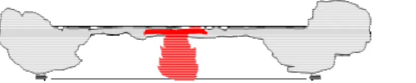
The air movements inside a tunnel can be created by pre-installed mechanical ventilation but can also be caused by natural reasons like buoyancy due to height and temperature differences or outside wind. At tunnel fires the smoke distribution inside the tunnel depends of the air flow. Airflows in tunnels can be divided into three different groups depending on their affect on the smoke distribution. The different groups are tunnels with low air velocities (< 1 m/s), moderate air velocities (1-3 m/s) and high air velocities (> 3 m/s). [5] At low velocities the smoke usually is clearly stratified close to the fire. As the tunnel walls cool the smoke, the smoke layer usually falls down and the full cross section can be filled with smoke, figure 1.
This situation will force fire fighting units to penetrate a smoke filled environment to be able to reach the fire site. The offensive fire fighting operation will be hard to manage if it will be necessary to penetrate long distances of smoke filled environment [8]. The practical maximum range of operation with a BA-unit in smoke filled tunnel environment will be approximately between 100 and 200 meters. The shorter the distance is to the fire, the higher will the radiation from the flames and the smoke be towards the fire fighting units [8]. This will have an impact on the units and will reduce their
possibilities to reach the fire site in order to suppress the fire. The higher the heat release rate is from the fire, the greater the impact will be on the fire fighting units from both the flame radiation and the heat flux from the smoke [3].
In very short tunnels, where the fire creates smoke with a high temperature, the stratification can be kept the full length of the tunnel. In tunnels with only natural ventilation and with no or only flat slopes, the air velocity at many times is less than 1 m/s [9, 10]. For such tunnels even small fires can cause long distances of back-layering.
For a fire fighting operation to succeed, the emergency services must be able to control, or at least adjust the operation to the flow of air in the tunnel. To be able to do an effective offensive fire fighting operation, the back-layering effect and the heat radiation from the smoke must be controlled and minimized.
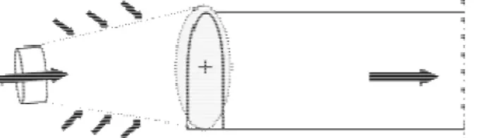
For air velocities between 1 m/s and the critical air velocity the length of the back-layering can vary between zero and 17 times the tunnel height, figure 2 and 3 [5].
Figure 2 Smoke progression in a tunnel with an airflow that is approximately 1 m/s
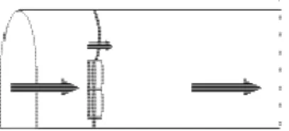
Figure 3 Smoke progression in a tunnel with an airflow that is between 1 and 3 m/s
For air velocities over 3 m/s – the critical velocity, no back-layering effect occurs at normal size fires, figure 4.
Figure 4 Smoke progression in a tunnel with an airflow that is over 3 m/s
As soon as the air starts to flow inside the tunnel, the turbulence can destroy the stratification of the smoke. If the tunnel is filled with smoke it will reduce the possibilities for both the evacuation of people in danger and the fire and rescue operations downstream the fire. But as the environment, regarding toxicity and heat radiation from the smoke layer, is improved downstream the fire as well as it controls the back-layering and gives the rescue services a possibility to reach the fire, the advantages with ventilation usually outweigh the disadvantages in small and moderate sized fires.
To be able to control the direction and the velocity of the air in the tunnel, the emergency services can either use mobile fans or the pre-installed ventilation systems in the tunnel. Tunnels can be equipped with different types of ventilation systems. This can for example depend on if it is a road, rail or a
metrotunnel, how long the tunnel is or the amount of traffic. The tunnel can, normally, have natural ventilation, longitudinal ventilation systems or transverse ventilation system. In tunnels with natural ventilation system the emergency services have to be able to either just follow the natural conditions or use mobile fans to produce the longitudinal air flow through the tunnel. In tunnels with longitudinal or transverse ventilation systems the emergency services have to be able to use these systems to create the best conditions for the operation and can in some cases use mobile fans to support the installed
systems. In this paper the ventilation of tunnels with mobile fans is presented, analyzed and discussed. SMOKE AND HEAT VENTILATION WITH MOBILE FANS
Mobile ventilation is a commonly used method when fighting compartment fires in normal buildings. The purpose with the ventilation is either to create an overpressure in adjacent areas around the fire compartment or to evacuate smoke from the fire compartment itself. For this purpose the emergency services normally uses medium flow (8-9 m3/s) mobile fans (PPV-fans).
The experiences and routines that have been developed in the emergency services for ventilation operations in fighting compartment fires are not automatically applicable for use at a tunnel. Because of the differences in geometry between ordinary buildings and tunnels, the normal recommendations concerning the use and position of the fan in relation to the opening is not the same and special tunnel ventilation routines has to be used. The size of the fan (i.e. the capacity – pressure and primary flow), the tunnel geometry, the ambient conditions and the size of the fire are critical parameters and will decide how effectively the ventilation will be. If ventilation with mobile fans is to be used, the choice is either to use high flow (>30 m3/s), usually lorry mounted, fans with high capacity or to use
combinations of the smaller, medium flow, PPV-fans the emergency services usually use for compartment fires. There are three main differences between using mobile fans for offensive smoke ventilation in tunnels and in compartment fires in buildings.
1. In a compartment fire the dynamic pressure produced by the airflow is used to create a slight static over pressure inside the compartment. The purpose is to create a pressure difference that will force the hot smoke out from compartment to the surroundings. In a compartment in a building there usually is a big increase of the cross-section area inside the inlet opening. In tunnels the cross-section area usually are similar the full length of the tunnel.
2. In tunnels the fans are used free blowing and the area inside the tunnel can be counted as decompressed. The static overpressure on the outside of the tunnel is used to prevent any flow in opposite direction along the tunnel walls and through the opening, figure 5. But it is mainly the dynamic pressure (the flow) from the fan that creates the air flow in the tunnel and not the static overpressure.
3. Tunnels are also relatively long and they present normally a high counteracting resistance that the dynamic pressure created by the fan has to overcome. [4].
The capacity of the single PPV-fan is too low to be effective for using in tunnel fires, except if it is a very short tunnel with a small cross-section area [4, 20]. In general it is the primary flow (air flow through the fan
)
and the force created by the fan that are the important parameters when comparing fans. The primary flow will always pull in entrainment air in the air cone, but the entrainment air should not be counted as a single value in itself. It is the force created by the primary air flow that decides the amount of entrainment air into the air cone and by this it is therefore the primary flow that should be compared.The influence of tunnel geometry and outside wind on the ventilation effect
If the counteracting resistances (geometry, ambient wind, the fire, etc.) are too high, the fan, or the set of fans, cannot create a dynamic pressure strong enough to force the direction of the counteracting flow to turn around. The result will be either a short circuit of the air flow over the fan, figure 6 or that the air flow is re-directed only in parts of the tunnel length, figure 7. In those cases when the counteracting flow and the flow created by the fan are of similar magnitude, a special phenomenon can be seen. The fan creates a flow in the middle of the cross section, but the ambient wind still creates a counteracting flow at the tunnel walls, figure 8. [4, 12]
To understand the effect from the ambient wind, one of the most important questions is the impact from the wind on the tunnel portals. For buildings this is normally presented as static pressure
coefficients and pressure profiles. The uncertainties how these apply on tunnels are considerable as not much research can be found in this field. Most pressure profiles are developed for closed buildings. [1] Already for buildings with large openings these pressure profiles can be uncertain. With tunnels the uncertainties are even larger. Existing equations for normal buildings cannot be applied on tunnels unless adjusted for the special conditions tunnels offer. The local geometry is significant for the pressure the wind will apply on the tunnel portals. Therefore the variations between different tunnels can be considerable. Simplified the force that the outside wind applies on the tunnel can be described as the summary of the pressure at the portals times the tunnel cross-section area. The airflows at the tunnel entrances are usually very turbulent in tunnels with natural ventilation. It is not unusual with outgoing air flows close to the tunnel walls and an ingoing air flow in the centre of the cross-section [10].
New research also indicates that the flow through large openings in buildings and wind induced flows in tunnels are being flow driven instead of being pressure driven. [1, 11]. A newly finished wind tunnel study [11] shows that the porosity - the size of the tunnel opening in relation to the blockage area of the surrounding mountain, the length, i.e. the resistance in the tunnel and the direction and velocity of the outside wind, are of significant importance for the wind induced flow in the tunnel [11].
As the flow inside the tunnel influence the fire growth and the maximum HRR [3, 16, 17, 18] as well as the tactics of the emergency operation, the IC need to follow the actual conditions in the tunnel. The IC should also be aware that the metrological conditions can alter during the time of the operation and that both the ambient wind and the fire in the tunnel are dynamic processes that have to be monitored. In tunnels with considerable slopes, the buoyancy effect created by the heat from the fire can
counteract with the natural airflow in the tunnel. When the buoyancy overcomes the wind induced flow, the airflow in the tunnel can suddenly reverse and put the emergency personnel at risk. The IC therefore needs to monitor not just the fire, but also the ambient conditions in respect to the emergency personnel’s safety inside the tunnel.
High flow fans
Previous tests performed [19] at the not yet opened 1100 meter long Kalldal railway tunnel in the north of Sweden, showed that high flow mobile fans effectively can create the desired airflow and thereby ventilate the tunnel. The chosen HRR was made considerable lower, only 2,6 MW instead of the commonly used 15MW in similar tunnels, to prevent damage on the already installed technical equipment in the tunnel. The main aim of the tests where to verify a mathematical model for deciding the required capacity of ventilation given the HRR and the size of the tunnel. The achieved test results corresponded well with the calculated air velocity in the tunnel, but also showed the efficiency of high flow mobile fans. [19] With these fans, a similar method as in compartment fires was shown effective. The fan where placed outside the tunnel entrance and tilted so the air cone fully covered the tunnel opening. If the capacity of the fan is big enough the over pressure at the opening prevents back flow close to the tunnel walls and the primary flow through the fan with the additional entrainment air will ventilate the tunnel, figure 5.
Combinations of more than one medium flow fan (PPV)
The access to high flow fans is unfortunately low among both emergency services and tunnel operators around the world. Tunnel openings can also be located in inaccessible areas where high flow fans are impossible to use. Railway tunnels in rural areas can be unapproachable unless covering the last distance by foot. This in combination with that most fire units already are equipped with PPV fans makes it interesting to compare for which tunnels and under what conditions combinations of PPV fans can be used with a desired effect.
Previous ventilation test in the Masthamn tunnel in Stockholm showed that it is effective in shorter tunnels to use combinations of ordinary PPV fans in order to create an airflow and by this ventilate the smoke from the tunnel. [20] The test also showed that it is more effective to place the smaller
combinations of fans in a parallel combination instead of a serial combination. At the tests the optimal location for the fans where tested – one tunnel height outside the tunnel opening, at the tunnel opening or one tunnel height inside the tunnel. The highest velocity where achieved when the combination of 4 PPV fans where located one tunnel height inside the tunnel. For locations outside the tunnel a back flow occasionally could be seen at the tunnel walls. This implies that the pressure is not enough to create a flow through the full cross-section in the full tunnel length. As the PPV fans create a lower positive static pressure inside the tunnel than the high flow fans, the location inside the tunnel protects the fans from side wind effects and makes the full primary flow enter the tunnel. The location inside the tunnel results in no static pressure at the tunnel opening but instead use the dynamic pressure created by the flow to ventilate the tunnel.
This will only be possible at short tunnels, with small cross-sections and low counteracting ambient winds. If the ambient wind pressure at the opposite tunnel opening and the wind induced flow inside the tunnel will overcome the fan induced flow, the fans will not succeed to reverse the air flow in the full cross-section or in the full tunnel length, figure 7. For strong counteracting winds the air short circuits over the fans, figure 6. If the forces of the wind, or the buoyancy, are of similar size as the fans, the two bi-directional flows will meet in the tunnel. Either one or both flows turn towards their entering tunnel opening or a flow through the full tunnel length is created by the fans in the middle of the cross section while the wind create a flow in the other direction at the tunnel walls, figure 8.
Figure 6
Short circuit over the fans
Figure 7
Reversed fan flow due to counteracting winds
Figure 8
Tunnel seen from above with back flow along tunnel walls
PPV in combination with a tunnel cover
To be able to secure that ventilating with combinations of smaller fans is possible, even when there is a counteracting wind or the buoyancy effects counteract the desired flow direction, a tunnel cover can be mounted at the location of the fans at the tunnel opening. The tunnel cover prevents the short circuit over the fans and supports the effect of the fans. The primary flow through the fans creates a pressure difference on either side of the tunnel cover and if openings are placed in the tunnel cover around the fans, entrainment air can be let into the tunnel and increase the flow, figure 9.
Figure 9 Schematic effects when using a tunnel cover to support the PPV fans
The use of the tunnel cover can be divided into three steps. First the tunnel cover is raised and placed over the fans. The wind induced counteracting flow in the tunnel stops and a static over pressure can be seen at the tunnel cover as it curve in the wind direction. Secondly the fans are started and the tunnel cover prevents the air to short circuit over the fans. As the air flow in the desired direction is stabilized, the static pressure at the tunnel cover is changing. The force from the primary flow instead creates an over pressure on the outside of the tunnel opening and creates an under pressure on the inside of the tunnel cover. The third step is to let entrainment air through the tunnel cover and in to the tunnel. As long as the fans can overcome the static pressure from the wind on the opposite tunnel opening, the air flow from the fans, with the additional entrainment air, will ventilate the tunnel in the desired direction [12].
Previous tests performed [12] in the 637 meter long Stadsgård tunnel, verified that the air flow in the tunnel could be reversed in the full cross section. The test where set up using a tunnel cover in combination with the same set of four PPV fans that were used in the prior Masthamn tunnel tests [20].The fans did not succeed to reverse the wind induced flow in the full tunnel cross section without the support from the tunnel cover. Instead the situation, as shown in figure 8 with a back flow along the tunnel walls, was created. The total volumetric primary flow in the test were approximately 34 m3/s. Regarding the primary flow it were comparatively equal to the flow at the high flow fan that were used in the Kalldal tunnel tests [12, 19]. It should although, again, be noted that the positive pressure created is weaker for the PPV fans than for the high flow fan. Other combinations of fans were tested, but with less effective results than with the four PPV fans.
Tests [12] were performed at two different occasions with two different ambient situations that created different counteracting air flows in the tunnel. Without the tunnel cover, the maximum velocity achieved in the middle of the tunnel, significantly differed between the two test occasions. With the tunnel cover, the maximum velocities of the air flow in the tunnel were similar between the two tests. This indicates that the full primary flow and the entrainment air where flowing in the tunnel, regardless of counteracting wind at both the two different occasions.
All fans, or combination of fans, will though have a maximum counteracting wind velocity that it can overcome. The tunnel cover will not work with all types of fans at all occasions, but regardless of type of fan the tunnel cover support the capacity of the fan and prevent short circuit of air. The tunnel cover could also support high flow fans placed at the tunnel opening in those occasions where the
counteracting forces are close to the capacity of the used fan. But when using large high flow fans under relatively normal fire conditions and in moderate length of tunnels, this is not necessary as the fan itself creates enough force and flow [12].
RECOMMENDATIONS FOR CHOICE OF EQUIPMENT AND METHOD
The emergency operation could easily grow into a complex situation, where the IC has to make judgments and decisions based upon few facts and uncertain information and it is of great importance that there are thorough contingency planning made on beforehand. All emergency services with tunnels within their action area should make adequate planning and preparation for the object of interest. The contingency plan has to be developed on basis of the objects as well as the available resources from the emergency services. The shown, table 1, should be seen as an example for the usability for the three different methods in case of the need for a ventilation operation in a tunnel.
Based on the results from earlier mentioned tests [8-13] the three different methods have been compared.
1. A set of four parallel medium flow fans placed one tunnel height inside the tunnel. 2. A set of four parallel medium flow fans placed one tunnel height inside the tunnel in
combination with a tunnel cover.
3. One single high flow fan placed one tunnel height outside the tunnel.
These different methods are then compared for three different tunnel lengths, three different cross section areas and at some counteracting airflows inside the tunnel. The values have been calculated by using the equations developed by Ingason and Romanov [13] and later verified and adjusted for counteracting wind in the research project in co-operation between Mälardalen and Gävle Universities. [9, 11, 12]. The surface roughness in the tunnel was set equivalent to blasted rock, approximately 200 mm. The pressure drop over the fire was set to 10 Pa. To fulfil the acceptance criteria the reversed velocity had to reach the level moderate air velocity or higher. The original air flow also had to stop or reverse in the full cross section area. No back flows along tunnel walls were allowed. For counteracting wind induced velocities over 1 m/s, in longer tunnels with larger cross section areas, complementary tests have to be performed as the equations not have been validated for higher counteracting wind induced velocities, especially regarding bi-directional flows. Complementary tests are planned and will be performed in the Kalldal tunnel during spring 2008.
→Tunnel length ↓ Tunnel area 250 m 1000 m 2000 m ↓ Counteracting wind in tunnel
10 m3 1,2 and 3 1,2 and 3 2 and 3 0 m/s
1,2 and 3 2 and 3 2 and 3 1 m/s
1,2 and 3 2 and 3 2 and 3 2 m/s
30 m3 1,2 and 3 2 and 3 2 and 3 0 m/s
1,2 and 3 2 and 3 2 and 3 1 m/s
2 and 3 2 and 3 2 and 3 2 m/s
50 m3 2 and 3 2 and 3 2 and 3 0 m/s
2 and 3 2 and 3 2 and 3 1 m/s
2 and 3 ** ** 2 m/s
Table 1
Possible methods (see above) for ventilation at different tunnel geometries and counteracting wind induced velocities inside the tunnel [9-13, 20]
** Complementary test will be performed during spring 2008
As shown in table 1 the combination of medium flow fans (1), with acceptable safety margins, only can be used for reversing flows in shorter tunnels (≤250 m), with small or moderate cross section areas (≤30 m2). To support the existing direction the combination could be used without length limits. It should though be noted that in cases where the outside wind direction is not stable and at risk of reversing the used method, for the fire fighters safety, should be carefully considered. In tunnels with longer distances to the location of the fire the fan, or combination of fans, should be able to withhold the reversing flow due to changing outside wind direction, the required time for the fire fighters to
retreat from the tunnel. As the outside wind direction changes relatively slowly over time [9, 10] the required safety can be kept, as long as the IC keeps himself updated of the outside wind conditions. For longer tunnels (1000 m – 2000 m) with larger cross section areas (30 m2 - 50 m2) two different methods can be used; large high flow fans (3) or combinations of medium flow fans with the support of a tunnel cover (2). Both methods have its advantages and difficulties. For tunnels with good connecting infrastructure at the tunnel openings lorry mounted fans can be altered from one tunnel opening to the other in case of the changing of strategy, without the need of de-mounting of a tunnel cover. The combination of medium flow fans and a tunnel cover, on the other hand, can be used at tunnel openings where larger lorry mounted fans can’t reach. The frame of the tunnel cover could also be mounted at the up-stream side of the tunnel, when only supporting the existing direction, to prepare for changing wind directions or decreasing outside winds in case of tunnel slopes counteracting the wind induced flow. The system with a tunnel cover in combination with a high flow fan could theoretically be used in very long tunnels, but have not yet been verified by full scale tests. The choice between the presented methods should be done as a part of the emergency services contingency planning based on the actual objects, available resources and economic presumptions.
DISCUSSIONS
The size of the fire is together with the length of the smoke filled distance from the entrance of the tunnel to the fire site, probably are the factors that will affect the fire fighting operation in the most direct way. The air flow in the tunnel will have a large impact on both these factors. The HRR and the fire growth rate will partly be affected by the velocity of the air flow. The movement of the smoke will follow the flow of the air. To create an air flow with a ventilation operation without the knowledge of how the flow will affect the fire and by this the production of heat and smoke can change the situation from a possible, from fire suppression point of view, to a hopeless fire inferno. On the other hand, a ventilation operation can change the fire fighting situation from a situation where nothing can be effectively done, to a situation where it is possible to suppress the fire. Ventilation will probably be a method that has to be used, at least in occasions where the fire is medium sized or larger. Not
ventilating the tunnel as an active decision based on the facts at the fire site can be a wise decision, but not ventilating the tunnel because of its complexity is not the right way to handle the emergency operation.
The use of ventilation is a common way for the emergency services to handle compartment fires in building. With this experience routines has been developed and adopted. Almost all ICs know that ventilation operations can change a bad situation to a better, but it can also change a bad situation to a much worse. To use ventilation on a compartment fire in a ventilation controlled stage of the fire will increase the HRR of the fire. In a fire in a tunnel the situation has to be monitored from another
perspective – the fire load. In the road tunnel the fire load can be simplified in types of vehicle and type of cargo. Fires in cars, lorries and buses are probably fires that will not exceed a HRR of 30 to 40 MW. In these cases the environment, regarding toxicity and heat radiation from the smoke layer, is improved downstream the fire, considered that the ventilation does not influence the HRR. The air flow will control the back layering, the heat radiation and gives the emergency services a possibility to reach the fire in order to suppress it. The advantages with ventilation usually overweight the disadvantages, especially when the fire starts to decay and there is no risk for further fire spread. If the fire is large, or if there is risk of fire spread to more fire load, the situation can be different. In these cases increased airflow can result in a much worse situation.
CONCLUSIONS
The tactical situation for the IC is not just to monitor the fire and smoke conditions, the handling of people in danger must be prioritised.
The use of ventilation can have other purposes than just support the fire suppression operation. For example the different ventilation methods can be used to;
− Create a longitudinal air flow and by this support the evacuation upstream the fire. − Create a longitudinal air flow and by this control the smoke so that the fire fighters can
approach to the fire site. The velocity of the air flow should only prevent the back-layering against the airflow. Air flow should be maintained at the speed of the critical air velocity. Higher velocities can make the fire spread to fire load down-stream the fire.
− Increase the flow in the tunnel to reduce the concentration of heat and toxicity downstream the fire site. This ventilation should not be used if the fire load is large, because it will increase the HRR.
− If the fire fighting operation can not control and suppress the fire supported by a longitudinal air flow due to for example a large fire load and there are people in danger downstream the fire reversed ventilation can help. The direction of the airflow can be reversed after the unaffected tunnel area is evacuated. People in danger that originally where downstream the fire will now be in a smoke free environment and can be reached by the emergency services.
− Extraction of the smoke from the affected sections or areas of a fire.
Combinations of medium flow fans only can be used for reversing flows in shorter tunnels, with small or moderate cross section areas. For longer tunnels with larger cross section areas two different methods can be used; large high flow fans or combinations of medium flow fans with the support of a tunnel cover.
The emergency operation must be objective orientated. If the objective is to rescue people in danger the choice of strategy and tactical approach has to be based on this. If an offensive fire fighting operation is to be done, it must support the rescue of people in danger. To make this judgement, the time factor has to be a part of the operation. If the ventilation operation is to support the fire suppression operation, a quick suppression can be necessary if the HRR should increase.
The conclusion is that an emergency operation has to be a well judged mix of different methods that supports the objective of the emergency operation. Ventilation operations can and should be a method that is used when fighting fires in tunnel. To make the right decision at the right time, demand a high level of expert knowledge from the IC. It also demands usable methods that can control the smoke and the fire behaviour. As the result from an emergency operation depends on the conditions at the fire site and the effective use of the available resources, it is important that the methods used is a part of a contingency planning and not invented at the scene of the fire. The contingency planning should be used as a decision support for the IC. The decision making will though be a dynamic process that follows the course of events at the scene of the fire.
ACKNOWLEDGEMENTS
The tests in the Masthamn and Stadsgård tunnels were performed with the kind permission from Stockholm Harbour and SL, the Stockholm Metro. At the tests in the tunnels used for rail traffic Stockholm Metro has contributed with valuable help regarding safety planning, safety personnel, equipment and manpower. The wind tunnel tests that were performed to investigate some of the phenomenon that occurred in the real tunnels and to validate the equations regarding counteracting winds were sponsored by the Swedish Saving Banks Foundation. The authors would like to thank the above mentioned organizations, whom without this research would not have been possible to perform.
REFERENCE LIST
Journals:
1. Sandberg M, “An Alternative View on the Theory of Cross-ventilation”, The International
Journal of Ventilation, Volume 2, N:o 4, March 2004
2. Carvel R.O , Beard A.N, Jowitt P.W, Drysdale D.D, “Variation of Heat Release Rate With Forced Longitudinal Ventilation for Vehicle Fires in Tunnels”, Fire Safety Journal, Vol. 36, No. 6, September 2001, pp 569-596, 2001
Dissertations:
3. Lönnermark, A., “On the Characteristics of Fires in Tunnels", Doctoral Thesis, 83, Department of Fire Safety Engineering, Lund University, Lund, Sweden, 2005.
4. Kumm M, “Smoke Ventilation in Tunnels – using Mobile Fans”, Licentiate Thesis, 53, Department of Public Technology, Mälardalen University, Västerås, Sweden, 2005
Handbooks:
5. Ingason, H., "Fire Dynamics in Tunnels". In The Handbook of Tunnel Fire Safety (R. O. Carvel and A. N. Beard, Eds.), Thomas Telford Publishing, 231-266, London, 2005.
6. Burns, D., "Emergency procedures in road tunnels: current practice and future ideas". In The
Handbook of Tunnel Fire Safety (R. O. Carvel and A. N. Beard, Eds.), Thomas Telford Publishing, 231-266, London, 2005.
7. Bergqvist, A., Frantzich, H., Hasselrot, K., Ingason, H., "Fire and rescue operations in tunnel fires: a discussion of some practical issues". In The Handbook of Tunnel Fire Safety (R. O. Carvel and A. N. Beard, Eds.), Thomas Telford Publishing, 231-266, London, 2005.
Reports:
8. Ingason, H., Bergqvist, A., Lönnermark, A., Frantzich, H., and Hasselrot, K., ”Räddingsinsatser i vägtunnlar”, Räddningsverket, P21-459/05 (in Swedish), 2005.
9. Kumm M, ”The Influence from Outside Wind on Fires in Tunnels: Part A - A Comparative Study between Model scale in the Wind tunnel and Full scale in the Masthamn tunnel”, (In Swedish - Vindens påverkan på bränder i tunnlar - En jämförande studie mellan modellskala i vindtunnel och fullskala i Masthamnstunneln), Research Report MdH ISt 2007:03, 2007 10. Sandberg M, Claesson L, Blomqvist C, ”Köldinträngning i järnvägstunnlar – utveckling av ett
projekteringsverktyg ” (In Swedish), Kungliga Tekniska Högskolan, Högskolan i Gävle, 2002 11. Kumm M, Nyman H, Ingason H, Sandberg M, ”The Influence from Outside Wind on Fires in
Tunnels Part B - The Importance of Tunnel Entrance Geometry on Air Movements inside Tunnels” (In Swedish - Vindens påverkan på bränder i tunnlar: Tunnelportalgeometrins betydelse för luftrörelser i tunnel orsakade av yttre vind), Research Report MdH ISt 2007:04, 2007
12. Kumm M, Nordman F, ”The Use of Static Pressure Differences to Increase the Effect of Mobile Fans at Smoke Ventilation in Tunnels” (In Swedish - Användande av statiska tryckskillnader för att höja mobila fläktars kapacitet vid brandgasevakuering i tunnlar), MdH ISt 2005:1
13. Ingason H, Romanov L, Use of Mobile Fans in Tunnels, SP Report 2002:06, ISBN 91-7848-895-8, 2002
Symposium proceedings:
14. Bergqvist, A, “What can the fire brigade do about tunnel fires?”, 2nd International Symposium on Tunnel safety & Security (ITSS), 277-288, Madrid, Spain, March, 2006
safety & Security (ITSS), 41-47, Madrid, Spain, March, 2006
16. Carvel R.O, Beard A.N, Jowitt P.W, “A method for making Realistic Estimates of the Heat Release Rate of a Fire in a Tunnel”, Proc. 3rd International Conference on Tunnel Fires, Gaithersburg, Maryland, USA, 9th-11th October 2001
17. Carvel R.O, Beard A.N, Jowitt P.W, “The Influence of Longitudinal Ventilation and Tunnel Size on HGV Fires in Tunnel”, Interflam 2004, Edinburgh, Scotland, 5-7 July, 2004, pp 815-820
18. Ingason H, Hägglund B, Werling P, “Effects of ventilation on smoke spread in tunnels”, ITC Conference Tunnel Fires and Escape from Tunnels, Lyon, France, 5th – 7th May 1999, pp 407-416
19. Ingason H, Wahlström B, “Trial of a mobile fan for smoke ventilation in a railway tunnel”, ITC Conference Tunnel Fires, Basel, Switzerland, 2nd – 4th December 2002, pp 151-160 20. Kumm M, Ingason H, “Can combinations of small fans be used for smoke evacuation in