Page 1
Improving the time frame reduction for
reuse of roof rack components in cars using
Case-based reasoning
Supattarachai Sudsawat
Harish Acharya
THESIS WORK 2012
PRODUCT DEVELOPMENT AND MATERIALS
ENGINEERING
Page 2
Improving the time frame reduction for
reuse of roof rack components in cars using
Case-based reasoning
Supattarachai Sudsawat
Harish Acharya
This thesis work has been carried out at the School of Engineering in
Jönköping in the subject area Product Development and Materials Engineering. The work is part of the university’s master degree.
The authors are responsible for the given opinions, conclusion and results. Supervisor: Joel Johansson
Credit points: 30 ECTS credits Date:
Page 3
ACKNOWLEDGEMENT
First and foremost we offer our sincerest gratitude to our supervisor, Joel Johansson, who has supported us throughout our thesis with his patience and knowledge whilst allowing us the room to work in my own way. We attribute the level of our Master’s degree to his encouragement and effort and without him this thesis, too, would not have been completed or written. One simply could not wish for a better or friendlier supervisor. Thanks Joel
We would like to thank the Product development team of Thule for being very supportive in providing us with all necessary information contributing to the successful completion of thesis.
Last but not the least, we would like to thank our parents for their unconditional support all through our master’s programme.
Supattarachai Sudsawat
Page 4
ABSTRACT
Now a days where technological advancements are growing at a rapid pace, it has become a common norm for all the manufacturing companies to be abreast with these advancements for being competitive in market. This thesis deals with development of one such common norm for one of the products (Roof rack component) for company Thule. The main aim of the thesis is to curtail the products lead time to market and this was achieved by using an artificial intelligence technique i.e., Case-based reasoning (CBR). Roof rack component which is mounted on car roof is mainly constituted by two parts foot pad and bracket, this thesis main interest was concerned with only brackets and its geometry. This thesis is based on contemplating the already implemented concepts in this context, designer requirements and exploring better solutions. The methods of implementation adopted here was using CBR concept which is based on indexing , retrieve, adapt, review, retain and employing these concepts in form of an algorithm. The concept for developing the algorithm was based on Iterative closest point (ICP) approach which emphasise on assigning lower weight to pairs with greater point to point distance. The results portrayed are with respect to geometry and also with respect to application interface developed, which both together provides us a better solution.
Keywords: Artificial intelligence, Case-based reasoning(CBR), iterative closest
Page 5
Contents
1
Introduction ... 7
1.1 COMPANY PRESENTATION ... 7
1.2 THESIS BACKGROUND... 8
1.3 PURPOSE AND RESEARCH ... 10
1.4 DELIMITATIONS ... 10
1.5 OUTLINE ... 10
2
Theoretical background ... 11
2.1 HISTORY OF THE CBRALGORITHM ... 11
2.2 MAIN TYPES OF CASE-BASED REASONING METHODS ... 12
2.2.1 Exemplar-based reasoning ... 13
2.2.2 Instance-based reasoning ... 14
2.2.3 Memory-based reasoning ... 14
2.2.4 Case-based reasoning... 15
2.2.5 Analogy-based reasoning ... 15
2.3 CASE-BASED REASONING CONCEPT ... 15
2.3.1 Indexing construction of existing cases ... 16
2.3.2 Retrieve ... 16
2.3.3 Adapting case histories (Reuse) ... 17
2.3.4 Review (Revise)... 17
2.3.5 Retain ... 17
2.4 MODELS OF CBR PROCESS ... 18
2.5 MAIN ADVANTAGES OF CASE-BASED-REASONING: ... 20
2.6 DRAWBACKS OF CASE-BASED-REASONING: ... 21
2.7 EXAMPLES OF ALGORITHMS IN CASE-BASED REASONING: ... 21
2.7.1 Indexing and retrieval in case-based process planning for multi-stage non-axisymmetric deep drawing: ... 21
2.7.2 A case based reasoning approach for generating new product ideas: ... 27
3
Methods of Implementation: ... 34
3.1 INTRODUCTION: ... 34
3.2 REUSE CONCEPTS FOR BRACKET ... 34
3.2.1 First concept of searching bracket system (2006) ... 34
3.2.2 Second concept for searching bracket system (2011) ... 35
3.3 OUR CONCEPT ... 40
3.3.1 Implemented concept in Indexing construction of existing cases ... 43
3.3.2 Implemented concept in Retrieve ... 43
3.3.3 Implemented concept in Adapting case histories ... 44
3.3.4 Implemented concept in Review ... 46
3.3.5 Implemented concept in Retain ... 47
4
Finding and analysis ... 48
4.1 COMPARISON WITH PREVIOUS CONCEPTS ... 48
4.1.1 Comparing second developed system with new developed system ... 48
4.2 RESULTS ... 49
4.3 ANALYSIS: ... 50
5
Discussions and Conclusion ... 52
5.1 DISCUSSION ON METHODS ... 52
5.2 DISCUSSION ON FINDINGS ... 53
5.3 CONCLUSION... 54
Page 6
List of figures
Figure 1.1The roof rack product is adapted to new car-models by changing the foot pad and the
brackets components 9
Figure2.1: Using CBR algorithm for applying in Product conceptual Design for prototype machine 12 Figure2.2 An exemplar representation in terms of some of bird’s exemplars 13 Figure2.3 Case-based reasoning process applied to system of redesign components 16
Figure 2.4 CBR model according to Kolodner (1993) 18
Figure 2.5 The model of CBR process (modified Aamodt and Plaza, 1994) 19
Figure 2.6 CBR process model according to Finnie and Sun (2003) 20
Figure 2.7 Feature shape parameters of an extracted deep drawn part 24 Figure 2.8 Flow chart of the case retrieval algorithm for similarity analysis 25 Figure 2.9 Shape resemblance distance calculation chart of the first matched feature pair between
case#025 and new case 26
Figure 2.10 Similarity metric calculation chart between case#025 and new case 26 Figure2.11 shows the vector representation of two products, cell phone and ball pen 31
Figure 3.1 First version of search bracket system 34
Figure 3.2 Latest version of search bracket system 35
Figure 3.3 Indexing the bracket into the system that is generated from Solid works 37 Figure 3.4 All the similar brackets in the system that transforms the retrieve system. 38 Figure 3.5 Ranking of the similar brackets generated from the system 38 Figure 3.6 Comparison between the search bracket and old brackets. 39 Figure 3.7 Release the new design bracket in order to be the database for next search brackets 39
Figure 3.8 Current version for the searching bracket system 40
Figure 3.9 Standard deviation diagram (Own work, based (in concept) on figure by Jeremy
Kemp-2005) 41
Figure 3.10 Import the new bracket from the sketch 43
Figure 3.11 Similar brackets are provided from CBR algorithm 44
Figure 3.12 Used function for separated group of brackets 44
Figure 3.13 Comparing the search bracket with old bracket that are similar and only adapt a bending
point and angle of bracket 45
Figure 3.14 Top three brackets that are generated from the three criteria. 46 Figure 3.15 Comparing the search bracket with old brackets in case of the search bracket are not
matched with old brackets 46
Figure 3.16 Collect the new design bracket in order to be the database for next search brackets 47 Figure 4.1 Comparing the constraints of bracket design in previous and new concepts 49 Figure 4.2 comparison of results from different concepts with required search bracket 49
Figure4.3 Interface for searching the brackets new concept 50
Page 7
1Introduction
Today where the products life is shortened due to rapid advancement in research and technology, the major challenge confronted by manufacturing companies is structuring of product development process targeted to reduce the products lead time to market. The word structuring refers to core aspects of transformations needed in product development process suiting to the requirements of customers and other stake holders. There are many research papers describing various techniques and ideas on enhancement of product development process. This present thesis is mainly concentrated on exploring in a more detailed manner on how we can aggravate the product development process using one of the Artificial intelligence (AI) techniques named “Case Based Reasoning (CBR)”.
Over the last few years, case based reasoning (CBR) has grown from a rather specific and isolated research area to a field of wide spread interest. This project deals with application of CBR for Roof rack component in cars manufactured by Thule with prime interest on reducing the products lead time to market.
1.1 Company Presentation
Thule brand was first established in Sweden in 1942 by a Thulin family, when Erik Thulin an true outdoor lover put the name Thule on pike trap which he designed and started selling to fishermen of Scandinavia. Gradually he started adding more practical things to his company’s product range which ensured the growth of his business.
In 1960, the company began to concentrate on car related products and added more product categories by end of 1970’s and explored new markets around the world. In 1979 the Thulin family sold Thule to the publicly listed company Eldon but the entrepreneurship and drive has remained and Thule group continued to grow organically and by acquisitions of companies and soon evolved as a Thule Group with new product categories and markets in its portfolio[1].Since then the company is in growth mode.
Headquarters of Thule is in Malmö, Sweden and company presently has almost 50 production facilities all over the world with sales of over 5.7billion Sek (2010) and approximately 3100 employees. The major market for Thule is Automobile industry.
Today Thule is a premium brand used globally for a wide assortment of products with a focus on how to make easier for people around the world to bring their equipments and personal accessories when they are seeking to enjoy their life. Thule Group mission is to be “the number one choice of consumers around the world that want to transport their equipment safely, easily and in style”[1].
Page 8
The product and business areas:
Under the motto active life, the Thule Group offers products in four different areas[2] :
The product roof racks in cars are our main area of interest. KIT (referred to foot with bracket and foot pad) development at Thule is making of new variants of car contact parts (part of existing roof rack system) to fit new cars (new fits) on the market.
The requirements of this product being very high in terms of safety, load bearing capacity and crash testing etc. All the research and development are carried out in the Thule plant Hillerstorp, Jönköping in co-ordination with SP research institute, Borås.
1.2 Thesis Background
This thesis project is a part of ongoing research work on time frame reduction in variant rich products for Roof rack component in cars manufactured by company Thule. The main focus of research is aimed at curtailing the products lead time to market.
Page 9
The Product roof racks which are mounted on car roofs directly i.e. without the support of rails, as the roof rack consists a foot with bracket and foot pad which is designed based on the geometry of car roof directly. Hence this roof rack has to be adapted to all car models it is supporting. Adaptation process is achieved by modifying two components, the bracket and the foot pad (referred as Kit by engineers). The foot pad is a rubber pad on which track is standing on the roof and the bracket is used to fix the rack by keeping around the roof end. As the company acts in open market competing with car manufacturers, therefore it cannot get nominal data of car roofs. Instead of which they have to gather the geometrical information about car roofs by measuring. Once this information is collected for a particular car model, then foot pad is developed and rack is placed on foot pad as a virtual model[3].
Figure 0.1:The roof rack product is adapted to new car-models by changing the foot pad and the brackets components[3]
Traditionally the drawing of the assembly was created and used to search existing brackets and this was painful task and time consuming for engineers who instead would draw a new one, as list of brackets keep on increasing with models. Two projects one in 2006 and other in 2011 resulted in shortening of lead time by 40%. The system was implemented in two phases. During the first phase, in 2006, it was implemented as stand-alone software with an user interface based on parameter inputs. In 2011 the system was re-implemented as an add-in to the CAD-system presently used at the company. The reasons for re-implementing the system were that, even though speeding the search mechanism, it was time consuming to save new designs into the system, it was error-prone to manually put in parameters representing new brackets, and the engineers felt that the hit rate was poor. When re-implementing the system as an add-in to the CAD-system it became easier to the engineers to store information about the new designs. It also became easier to interpret the information in the system, avoiding errors. Due to these improvements the system is now used on an everyday basis by several engineers in several countries.
Even though the engineers do find re-useable designs it is not the ones that the system presents as top-rated that are re-used. When interviewing some of the
Page 10
engineers they state that it is seldom that the selected design to re-use is among the top-ten listed by the system. This was achieved by using an Artificial intelligence (AI) technique- Case Based Reasoning (CBR) for searching of brackets and the results obtained after implementation is detailed below.
Search done in milliseconds instead of hours when done manually.
Hit rate better than manual.
1.3 Purpose and research
This thesis project concentrates on exploring broader prospects of improving this present technique by enhancing the Kit development process further and also suiting the requirements of designer.
The aim of this thesis work is:
Categorize the implemented concept with respect to scientific literature.
How can we inculcate new or modify the Case-based reasoning Algorithm in a way reducing the time frame for reuse of brackets in roof rack products?
How can we make the process more refined and compatible for the designer?
1.4 Delimitations
The main purpose of this master thesis work is to design and develop a system for reuse of roof rack components for variant rich products by using Case-based reasoning. By which this thesis constrained merely to parameters in design which being geometries of roof rack components. Therefore the effects of the mechanical properties, materials properties, manufacturing aspects and also costs are not taken into consideration in this thesis.
1.5 Outline
This master thesis is divided into following chapters.Chapter1: Introduction in the problem, Chapter 2: Theoretical background about Case Based Reasoning Algorithm (CBR), Chapter 3: Implementation, this chapter describes ‘how to implement CBR system to variant-rich products’, Chapter 4: The results from the CBR system are presented and discussed, Chapter 5: Conclusion of this thesis work, Chapter 6: Describes the future work.
Page 11
2 Theoretical background
Theory that is used in this thesis is Case-based reasoning Algorithm (CBR) by which Case-based reasoning support design decision of cases (brackets). Firstly, whole concepts of case-based reasoning are assigned to the system and then using CBR to define reasonable cases to consider in designed cases is the goal of this thesis.
2.1 History of the CBR Algorithm
Case-based reasoning imitates human thinking trying to make a decision based on previous experiences. The roots of case-based reasoning in AI are found in the works of Roger Schank on dynamic memory. The center role that reminding of earlier situation(episodes, case) and situation patterns (scripts, MOPs) have in problem solving and learning[4]. During 1977 to 1993, Case-based reasoning Algorithm (CBR) was rapidly regarded as reasonable high-level model for understanding processes by which it concentrated deeply on problems, for example how humans generate theories about new situations or problems by relying on their previous experiences and how humans learn, understand a new skill to solve problems. The goals of these algorithms were to build decision support systems making work simpler for users. Many CBR model systems were created during this period ,for instance the first system that might be called ‘ a case based reasoner’ was the CYRUS system, developed by Janet Kolodner[5, 6],at Yale University (Schank’s group) after that there were successively development many systems based on CBR which being MEDIATOR[7] , PERSUADER [8] , CHEF[9] , JULIA[10] , CASEY[11].
Moreover Case-based reasoning is brought to use for the study of analogical reasoning [12] and also from theories of concept formation, problem solving and experiential learning within philosophy and psychology [13-15]. Various CBR workshops were organized in 1988, 1989, and 1991 by the U.S. Defense Advanced Research Projects Agency (DARPA) by which events are provided to create the official discipline of Case-based Reasoning[16]. In addition, other significant artificial intelligence conference such as ECAI (European Conference on Artificial Intelligence), IJCAI (International Joint Conference on Artificial Intelligence) in which CBR system has been part of their usual programs[16]. In 1993, the first European workshop on Case-based Reasoning (EWCBR-93) was created in Kaiserslautern, Germany [17].Thereafter, many international workshops and conference about CBR have been created in different parts of the world.
In recent years, Case-based reasoning has been adapted in many fields. For instance there is Case-based reasoning technology for applying in Product conceptual Design given by Peigang et al. in 2011[18].Case-based reasoning is applied in the functional mode as structural and functional carrier, it is expressed in form of codes which match case parts and then they are evaluated to find the concept to solid parts as shown in the figure2.1 below
Page 12 Figure2.1: Using CBR algorithm for applying in Product conceptual Design for prototype machine[19]
2.2 Main Types of Case-based reasoning Methods
Case-based reasoning (CBR) model is supported in cases for organizing, retrieving, utilizing and indexing the knowledge retained in previous cases. Here many cases may be considered as specific experiences or can be utilized as a set of similar cases for retrieving and adapting to new cases. Moreover they may provide directly the solution to modified case if they do not have any differences in correlating two cases. As mentioned before, Case-based reasoning model is used to conceive solutions by comparing cases, adapting solutions and using knowledge from previous cases. This helps humans to learn deeply more about the model, solve problems and helps in designing system. While some cases might not comprise knowledge structure completely based on Case-based reasoning rather it is used only in a specific part of whole structure. Thus it might be concluded that Case-based reasoning model is usually used as interactive system within a whole system.
There are many ways for implementing Artificial intelligence systems to help in design or solve problems. These reasons might have some ambiguity about Case-based reasoning, particularly the way it can be adapted in a system. Thus, there is an attempt to clarify the Case-based-reasoning term to distinguish with other separate kinds of case-based reasoning and this is described in topics below.
Page 13 2.2.1 Exemplar-based reasoning
The term “exemplar-based reasoning” is defined from a classification of different views to concept definition into ‘the classical view’, ‘the probabilistic view’, and ‘the exemplar view’ (see[13]) as shown in figure2 below describing about the concept of birds representing in terms of exemplars. In exemplar view cases are organized based on the view that should be defined extensionally with case being referred to as exemplars .The term is a network structure of categories, semantic relations, case and index pointers by which three types of indices are provided as mentioned below[20]:
1. Feature links that point from problem descriptors to a case. 2. Case links that point from categories to its associated cases
3. Difference links pointing from categories to the closed case that merely differ small features.
These three types of indices is the network background in order to build general domain knowledge to support CBR tasks. A new case will be retained by searching for a matching case by which if a case is found with only small differences between previous case and new one, the new case might not be retained but will combine both cases to retain.
Page 14 2.2.2 Instance-based reasoning
This is specialization of the exemplar-based reasoning to a deeply syntactic Case-based reasoning method. Instance-Case-based reasoning has a duty to reward for lack of guidance of background knowledge from exemplar-based reasoning to get more detailed information in order to close in new instance. This is especially because of approach that they typically consider about nearest neighbor concept for new instances. Thus all information will be attempted to retrieve particularly from background knowledge in order to get most similar instances. On the other hand, exemplar-based reasoning has a target concept depending on only a few of the available details of information.
Basically; instance-based reasoning is a non-generalization approach to the concept learning problem addressed by classical, inductive machine learning methods [21]. The present thesis core concept is also based on this particular approach, where the instances are interpreted as brackets. This resemblance can be contemplated clearly in implementation part described in further topics.
2.2.3 Memory-based reasoning
This method is comprised of memory organization sets by which they will be accessing and searching in the memory to focus of the case-based knowledge. The utilization of parallel processing techniques is a characteristic of these methods, and distinguishes this approach from the others. The access and storage methods may rely on purely syntactic criteria, as in the MBR-Talk system [22].Moreover, CRAIG STANFILL and DAVID WALT [23] mentioned about memory-based reasoning that studying of cognition will be difficult to conceive of thought without memory. Another thing is the inability of Artificial Intelligence to achieve success in any broad domain or to effectively capture the notion of “common sense”.
Thus, the goal of memory-based reasoning is to make decisions by looking cases in databases that use similarity based learning. The memory-based reasoning solves and defines cases by using direct reference or databases to memory without using the rules.
This approach has a close resemblance to that of concept implemented in 2006 where the all the data has to be entered manually and the similar brackets is retrieved by comparison of input data exactly with respect to data inherited in memory of system. The similarity of 2006 implemented concept to this approach can related better in implementation part clearly mentioned in further topics below.
Page 15 2.2.4 Case-based reasoning
Case-based reasoning is used as a generic term in this thesis, it has a particular method that can distinguish based on approach towards solutions, which in case-based reasoning is case-based on the principle that a new problem-solving case can benefit from the solution of previous cases. The cycle of case-based reasoning comprises four activities [20]:
1. Depict the input problem and specify an index.
2. Retrieve similar cases to the new problem from the case library. 3. Revise or adapt the solution to satisfy the new problem
4. Retain the new solution once it has been confirmed or validated under some strategies.
Kolodner[20] describes that “ Case-based reasoning as adapting old solutions to meet new demands, using old cases to explain new situations, using old cases to critique new solution, reasoning from precedents to interpret a new situation”.
2.2.5 Analogy-based reasoning
Analogical reasoning is based on the idea that problems or experiences outside the circumstances that we are currently dealing with may provide some insight or assistance to find a solution and it is often termed as a synonym to case-based reasoning. Analogy is a way of recognizing something that has not been encountered before by associating it with some related terms. Research on analogy reasoning is therefore a subfield concerned with mechanisms for identification and utilization of cross-domain analogies [3, 24].The main topic of study has been on the reuse of a past case, called the mapping problem: Finding a way to transfer, or map the solution of an identified analogue (called source or base) to the present problem (called target).
2.3 Case-Based Reasoning Concept
In this context we will explain more deeply about concepts of case-based reasoning and the process involved in application of Case-based-reasoning and the main attributes that defines the working of whole concept.
Page 16 Figure2.3 Case-based reasoning process applied to system of redesign components[25, 26]
2.3.1 Indexing construction of existing cases
Case indexing is the process of retrieving similar cases. The main two points that must be considered when creating a case index is firstly, the important feature must be indexed first and the case is then organized ensuring efficient and accurate search of case library. The classification of case index can be categorized according to the attributes that defines whole structuring of case for example a die casting part can be assigned with digits referred as case identification code representing product shape, filling system , functional components (Sliders and lifters), ejector system etc[27].
Secondly, indexing construction might be assigned in a way which engineer prefers designing a particular case i.e., the case index is structured based on preferences of the designer in way providing flexibility in retrieving the cases from case library.
2.3.2 Retrieve
The retrieval of cases in case-based reasoning operation is process to browse and select a relevant design case achieved normally by comparing similar previous design case with new design case.
Recalling databases or previous experience to find the similar cases that is suitable for problem solving. The usage of the term similarity in Case-based reasoning method will focus on similarity as a fuzzy relation between previous and new cases. Then there will be adapting previous case to solve a problem in new cases. In our thesis, we retrieve cases based on the “weights” that’s get assigned to each of case based on nearest neighbor corresponding to the search case parameters[28]. The parameter here is restricted to geometry and some of constraints developed based data collected.
Page 17 2.3.3 Adapting case histories (Reuse)
Adapting the current case with the retrieved similar case is critical in Case-based reasoning. Normally, new cases rarely match old cases exactly and thus it is necessary to adapt old solution to new case and we define the three general kinds of adaptation to define the suitable solution for the new cases:
1. Null adaptation means use an old solution and apply it to current design without adapting it.
2. Topological adaptation that separate the main structure of cases (for example the brackets have two kinds which being one with a hole and without hole )
3. Parametric adaptation that corresponds to the substitution or adjustment of parameter design (for example the angle of the last part of the bracket and the last bending point of brackets)
In this thesis, our emphasis is more on reducing products design and development time, thus decreasing costs and product lead time to market. Thus adapting case concern merely about the geometries of brackets, they do not need to notice about other properties in design as shown in the three concepts of adaptation above. Worth noticing though, is that type two and type three may cause very different impacts on the adaption process. For instance adding hole (topological change) to an existing design might be much cheaper than changing a wall thickness (parametrical change).
2.3.4 Review (Revise)
Once the adaptation process is finished then next step is reviewing the adapted case to the existing ones in a way making sure that adapted case is confronting to conditions of new case. If the new case matches to one of previous cases completely without any adaptation (Null adaptation), then the further sequential steps after adaptation in Case-based reasoning process is bypassed as pointed by arrow in figure-2.3. As the present adapted case matches to situation in one of the similar previous case, thus the further steps is not necessary to accomplish as it is already matches an existing case in case library.
Review step mainly focuses on evaluation to specification of new product variants and if any discrepancies are found then case is rejected and the whole process is repeated. Thus the cases which are passed by review step is retained in case library as new case.
2.3.5 Retain
After all the process of case-based reasoning (CBR) have done, the new or modified case (brackets) will finally be stored to database for returning back to system again for new case as shown in figure-2.3.
Page 18
2.4 Models of CBR process
In order to describe CBR process, several general models have been proposed and some of them are explained below.
Kolodner Model:
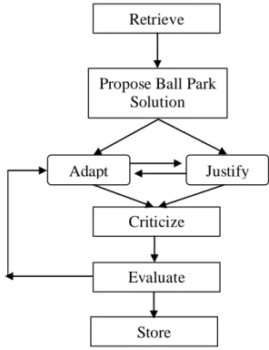
Kolodner (1993) considered CBR as a process containing the following steps shown in figure-2.4 which portrays case retrieval as primary step, proposing different solutions based on the extracted cases. Next is adaptation where the past solution is modified to fit in new situation, criticism of new solution , its evaluation based on external feedback and lastly storage of verified solution of the present problem in case base [19].
Kolodner emphasizes two main roles for CBR: [19]
Problem Solving:
Adaptation of ball park solution (within the scope) to new solution and then criticized, forms main aspect of CBR. If new solution fails it is adapted again.
Interpretive Task:
In this task a ball park (within the scope) interpretation is proposed, followed by justification process which tries to create arguments for proposed solution. Justification process compares and contrasts the situation with past cases, looking for similarities between new solution and others that accomplish the desired result.
Figure 2.4 CBR model according to Kolodner (1993) Retrieve
Propose Ball Park Solution
Adapt Justify
Store Evaluate Criticize
Page 19
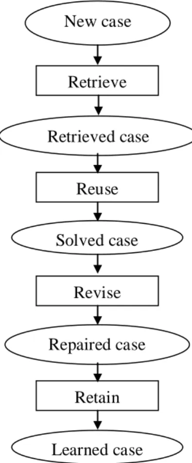
Aamodt and Plaza (1994) introduced a model which consists the following phases: [19]
Retrieve the most similar cases
Reuse the cases
Revise the proposed solution
Retain the new solution as part of new case
The model is commonly known as R4 model of CBR, because the process involved in this model can be represented by scheme comprising four REs as shown in figure-2.5. As we can see each step involves more specific steps, for example, retrieve includes identify, search, initially match and select (Aamodt and plaza, 1994).
Figure 2.5 The model of CBR process (modified Aamodt and Plaza, 1994)
However, these models assume that the case base is readily available “at once” for case retrieval and ignore the fact that case building is also an important task. Finnie and Sun in their work (Finnie and Sun, 2003) have taken in to consideration the preparation of case bases. They extended the model of Aamodt and plaza by adding a new step: “repartition, which builds a satisfactory case base based on utilizing similarity relations to the possible world of problems and solutions (figure-2.6)” [19]. New case Retrieve Learned case Repaired case Solved case Retrieved case Retain Revise Reuse
Page 20 New problem
New case
Figure 2.6 CBR process model according to Finnie and Sun (2003)
2.5 Main advantages of Case-based-reasoning:
Can be applied to broad range of domains: Case based reasoning can be applied to extremely diversified application domains. This is due to limitless number of ways of representing, indexing, retrieving and adapting cases[29].
Reason with incomplete or imprecise data and concept: The cases retrieved might not be identical to the current query case , but if there exists some defined measure of similarity to query case that’s enough as any incompleteness or imprecision can be dealt by case based reasoner. Although this may not relate to exact solution but at least the concept can be derived[29].
Reason in domains that have not fully understood or modeled: In context where insufficient knowledge exists to build a causal model of a domain, a case based reasoner can still be developed using only a small set of cases from the domain. The underlying theory of domain knowledge need not be quantified[29]. Repartition Retrieval Retaining Revise Reuse World of Solutions World of Problems
Page 21
2.6 Drawbacks of Case-based-reasoning:
Learning, although natural and intuitive, demands some careful considerations as to which cases are added in case library, and how[30].
Adaptation may be difficult or sometimes impossible for many domains. In others it is done with rules[30].
Matching process, if complex can add computational cost to CBR system, regardless of how well case library may be designed. In many cases, the distance calculations between the desired solution and actual solution can be difficult to make. This is from a conceptual as well as a computational point of view[30].
2.7 Examples of Algorithms in Case-based reasoning:
Case based reasoning has broad range of domain where it can be applied. Every application can be represented in terms of algorithm and thus we address it as case-based reasoning algorithms. Below we mention a few algorithms applied in different domains.
2.7.1 Indexing and retrieval in case-based process planning for multi-stage non-axisymmetric deep drawing:
Case based reasoning methodology adopted here is for computer-aided process planning (CAPP) for multistage, non-axisymmetric sheet metal deep drawing. This methodology addresses the indexing and retrieval of process planning cases. Planning cases are done based on feature-based representation of deep drawn parts. Efficient case retrieval is achieved by a feature-based similarity analysis between a new deep drawn part and existing parts in case library[31].
The below figure illustrates the frame work of Case based reasoning system for CAPP for multistage non axisymmetric sheet metal deep drawing. The major modules are case indexer, case retriever, case adapter and case library. Initially case library consists of few cases retrieved from traditional knowledge based systems or industrial practices. To facilitate case retrieval, each new deep drawn part with its object geometry is described using a feature based representation and it becomes input to the case indexer, which can identify deep drawn parts. Then it is passed to the next step i.e., case retriever, which extracts a case (from case library) that is most similar to the input case and here it employs feature-based similarity analysis. If the retrieved closest case doesn’t match the input case then it is passed to case adapter where it is tailors the retrieved case to match the requirements of input case. Finally the output is given to user and case is stored in library as a new historical case [31].
Page 22 2.7.1.1 Case representation:
A collection of deep drawing features are used here to model a sheet metal deep drawn part. All of these part features is to encapsulate a set of design and manufacturing information including geometric information such as shape, tolerance, surface finish and also includes non-geometric information like material parameters. A commercial CAD system, Solid Edge, is used to support the representation and extraction of feature model for all deep drawn parts in case library .
2.7.1.2 Case library:
The case library consists a number of cases defined in a frame structure that describes design requirements and process planning solution. The design requirements are defined by feature representation and the process planning is defined as a complete process plan for forming a flat blank to final deep drawn part , including all the process sequence with intermediate geometries and process parameters such as initial drawing coefficient , punching force, die profile radii , blank holding force etc.
2.7.1.3 Case Indexing:
It is important criteria in case based reasoning on which the effect of retrieval of most similar case from a large case library. For achieving this it is necessary that the indexing is done in proper way so that system can identify the closest quickly and easily. Here in this case feature geometric parameters and material parameters are used as indices. The feature geometric parameter is main factor that govern the similarity between newly deep drawn part and existing one in case library. The material parameters also influence the similarity match, but are less critical. To avoid any contradictory results the similarity is matched based on weight (importance) of each index.
2.7.1.4 Case Retrieval:
Case retrieval requires a combination of searching and matching. Here in this case similarity match is based on new deep drawn part and the existing parts using the following metric:[31]
where Sim- denotes the similarity metric between two deep drawn parts; Spart-geometry and Smaterial respectively denote part geometric and material similarity between two parts; wpart-geometry and wmaterial respectively denote
weights of part geometry and material.
The material similarity Smaterial between two parts in Eq.1 is defined as
Page 23
Smaterial = 1- Dmaterial (2)
It can be proven that Dmaterial ranges from 0.0 to 1.0 i.e., Dmaterial Є [0.0, 1.0],
hence Smaterial Є [0.0, 1.0]. For similarity value 0.0 indicates “most dissimilar”
and 1.0 indicates “most similar”. For resemblance distance value, 0.0 indicates “closest” and 1.0 indicates “most distant”. This notation applies all through this concept.
The part geometric similarity mentioned in Eq.1 is defined as aggregation of all the feature geometric corresponding deep drawing feature pairs in the new and old existing parts as shown below.
Spart-geometry = 2 *
2m+n
Where – feature geometric similarity between the ith matched feature pair in new and existing parts.
m – matched feature pairs applying to both new and existing parts(numerator is multiplied by 2)
n – number of unmatched deep drawing features either in new or existing parts. Further, is defined as the inverse of the geometry resemblance distance between the ith matched feature pair, and shown below:
= 1- (4)
– Geometry resemblance distance between ith matched
feature pair , which is expressed as a normalized Euclidean distance between corresponding features (shape, tolerance and finish).
The shape parameters are expressed as and θ, where and denotes diameter of the flange along the major and
minor axes; and denote diameters of the drawn cup along the major and
minor axes; and denote the curve radii of the drawn cup along major
and minor axes ; H- height of drawn cup and θ – taper angle of drawn cup; T- thickness of the sheet metal as shown in figure-3.1
Page 24 Figure 2.7 Feature shape parameters of an extracted deep drawn part [31]
Page 25 Figure 2.8 Flow chart of the case retrieval algorithm for similarity analysis [31]
Page 26 Figure 2.9 Shape resemblance distance calculation chart of the first matched feature
pair between case#025 and new case[31]
Page 27
In summary, to calculate the similarity metric the shape resemblance distance
between the ith matched feature pair is calculated first with
Eq.5 which is then substituted into Eq.4 to calculate the feature geometric similarity Є [0.0, 1.0] between the ith matched feature pair.
Spart-geometry Є [0.0, 1.0] between two parts is calculated by substituting into Eq.3. The material similarity is calculated Smaterial Є [0.0 ,
1.0] between two parts is calculated from Eq.2 . finally overall similarity metric is calculated by substituting Spart-geometry and Smaterial into Eq.1 resulting in Sim Є
[0.0,1.0].
Note that all the weights in these equations are determined by experience.
2.7.2 A case based reasoning approach for generating new product ideas:
In this approach a product is represented by a vector, which involves a number of product attributes. These attributes are defined based on user-centered design (UCD) paradigm i.e., the context of use and an interaction with users for the product is described by these attributes. By the product representation, a product database can be established and for a benchmarking product we use case-based reasoning technique to retrieve those products which are “sufficiently relevant” to the benchmarking one, from the database [32]. The functions of the retrieved products are the candidate for new ideas to be added onto the benchmarking product. All the retrieved products are screened manually for identification of creative and valuable ideas.
UCD is defined as “philosophy based on needs and interests of the user, with an emphasis on making products usable and understandable” [33]. The ISO 13407 standard also provides a frame work for applying UCD [34]. According to this standard UCD activities need to start at the earliest stages of product development: (1) understand and specify the context of use, (2) specify the user and organizational requirements (3) produce design solutions and (4) evaluate designs against requirements. UCD has been widely used in industry [35, 36] and some example applications are design of modern microelectronic products[37], design of a website [38], the design of a user interface of welding machine [39] and the design of new product concept [40].
2.7.2.1 Product Representation:
As mentioned above the product is modeled by a vector consisting of a number of product attributes. According to paradigm of UCD these product attributes are developed from five dimensions[32]:
1) Interface modality:
This dimension is used to identify the medium through which the product interacts with user. Here medium denotes a particular portion of the user’s body. Here it is put into three subdivisions sensory modality, response modality and positioning location. Sensory modality represents medium or
Page 28
Sensors through which the user receives messages sent from product for example sensory modality of a watch is visual and of a radio is audio. Next,
response modality denotes the medium through which the user responds or
manipulates the product; some of its attributes are face, neck, hand, foot etc. For example a pair of glasses involves two response modality attributes face and eyes. Finally the positioning location denotes the medium through which the user carries the product and related attributes are head, chest, hand, back etc. For example a pocket watch involves chest-waist.
2) Task:
The second dimension- task is to model the tasks to be performed by the user through using the product. According to users these are also categorised into seven groups they are eating, clothing, living, transportation, education/entertainment, working and healthcare. All these groups describe the tasks relevant to the definitions described by their names. For example cooking pot is for the processing of food- related to eating group, a washing machine is for cleaning purpose-related to clothing group, GPS is used for navigation purpose-related to transportation , email and tape recorder systems where one is for entertainment and education – related to education/entertainment, telephone and thermometer where one is used for communication and other is for inspection – related to working group and finally soap, wheel chair in which one is used for daily maintenance purpose and other rehabilitation purpose.
3) Physical feature:
This dimension is characterized by three features physical size, movability and scalability. The best example this group is notebook medium in size, portable and medium level in scalability.
4) Environment:
This dimension describes about the environment where the product is used. This is further characterized into three subdivisions which are number of users, indoor/outdoor place and the harshness of the environment. Numbers of users constitute for products usage example a television is for group and where as personal digital assistant is for single user. Similarly for indoor/outdoor we can cite an example such as printer which is only indoor use and walkie-talkie serves both indoor and outdoor and finally for harshness of environment the example is industrial computer which can be used in high temperature and high noise environment.
5) Users:
The final dimension users are characterized by the following demographic features; gender, age group, working industry and job position. The gender denotes to population of users in terms of gender, age group represents young, adult, child, infant and aged, working industry denotes to type of industry like agriculture, manufacturing, trade, service/education and government,
Page 29
finally job position is clustered as middle management, top management, office clerk etc.
Thus based on the representation scheme mentioned above a product can be modelled by a vector consisting 87 attribute values. Each attribute of a product can be valued in five scale points; extreme relevance (1.0), relevance (0.5), low relevance (0.25), no relevance (0). Below figure-3.5 shows the vector representation of two products, cell phone and ball pen.
Page 31 Figure2.11 shows the vector representation of two products, cell phone and ball pen[32].
2.7.2.2 Generation of New product ideas:
Based on the proposed product representation scheme, here they case based reasoning technique for generating new product ideas. The idea generation mechanism starts with bench marking the product, an existing product on which new functions are to be added. For this purpose we use the high value attributes (≥ 0.75) as keys to retrieve other products that are “sufficiently relevant” to the benchmarking product. All the retrieved products are screened and subsequently rated manually to determine the quality of the new ideas (i.e., how creative and valuable it is).
Page 32
Computing the relevance metric:[32]
If we take an already established product database, involving a large amount of products and each product is modelled according to proposed scheme –vector form.
Let represent the database, where
denotes the ith product and is the value of jth attribute.
Let denote the benchmarking product.
Let represent the relevance metric of the j-th attribute of the product B and . is defined below;
Let represent a set of high value attributes of product B. Some attributes in S is selected to from a key set, which are used to retrieve “sufficiently relevant” products. Define T ϲ S as the key set. Let represents the product relevance metric between products and B, with respect to set of attributes T. is defined below, where denotes the weighting factor of j-th attribute given by users i.e. users can intentionally gives preference on attributes in T
ϲ
Procedure of CBR:
The concept above can be used to develop a product innovation retrieval system, called PIRS. The procedure for using the PIRS to generate new product ideas is given below[32]
Step-1 : Initialization
Assign R_set = ø , A_set = ø
Ask user to determine the benchmarking product B
Step-2: Determine , the set of important attributes for product B.
Step-3: Ask the users to select attributes in S to form several key sets and give for each attribute in
Step-4: Retrieve “sufficiently relevant” products from the products database
Page 33
Ask the users to determine a relevance threshold Retrieve and place the “sufficiently relevant” products in
R_set that is
Step-5: Ask the users to select creative and valuable product ideas R_set and place them in A_set.
In summary, here we have seen the approach of case based reasoning in generating new product ideas. A product is modelled by 87 attributes based on user centered design (UCD) paradigm. For each attribute, a product is assigned a 0-1 value and higher the value, the more important is the attribute. For a bench marking product, some of its important attributes are manually selected as keys for retrieving from database the products that are “sufficiently relevant” to the bench marking product. The main functions of these retrieved products are taken as candidate new functions of the benchmarking product.
Page 34
3 Methods of Implementation:
3.1 Introduction:
The approach applied here is a simple one where we used the knowledge gained through literature study and utilized it in finding a suitable concept that is feasible to adapt to our thesis requirements. Case based reasoning concept on a whole is interpreted in terms of algorithms that define the way the application works. In the following topics we discuss in detail about different algorithms with respect to different contexts and also about concepts pertaining to our thesis.
The main intention behind citing this example of Case-based reasoning applications is to understand how diversified the concept of case-based reasoning can be implemented in different contexts.
3.2 Reuse concepts for bracket
3.2.1 First concept of searching bracket system (2006)
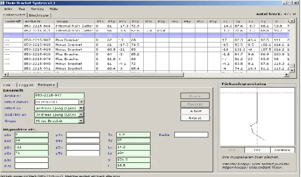
At the beginning before the development of present searching bracket system, there was a concept for search bracket system which was implemented as stand-alone software with an user interface based on parameter inputs. Searched brackets will be displayed in a table with all the parameters as shown in figure-3.6.
Page 35
The system was re-implemented in 2011, the reason was even though speeding the search mechanism, it was time consuming to save new designs into the system, it was error-prone to manually put in parameters representing new brackets, and the engineers felt that the hit rate was poor.
3.2.2 Second concept for searching bracket system (2011)
The development of new bracket system was to overcome the draw backs in previous implemented system. Therefore this developed system was implemented with an add in to CAD system and thus it became easier for engineers to interpret the results in more effective manner.
The implemented system uses Case-based reasoning an artificial intelligence technique for obtaining the desired results. The effectiveness of this is described in thesis background topic mentioned above.
The system implemented is shown in below figure-3.7 and the detailed description of functioning of system will be described in further topics.
Page 36
3.2.2.1 Fuzzy set approach in Case-Based System
Implemented system uses a “Fuzzy set approach” in Case-based reasoning process. This concept means a set of primary objectives that are presented and model the meaning of ambiguous terms such as length, thickness, and process multiple memberships in classification[41]. By which this approach provides detailed attributes in working system. First, it allows numerical features to be converted into fuzzy terms to simplify the matching old brackets. Second, it permits old brackets in the different domain (dimensions) to be comparable with search bracket [41]. So using this concept into CBR algorithm to search similar brackets is detailed below:
p is the number of parameters (Points, Angle, and etc.) n is the number of brackets
i = 1….n j = 1….p
S is the search bracket.
B is the old brackets in the database. Bi is one bracket in the database.
To start with the distance between search bracket and each old bracket are calculated. The calculated difference in distances is assigned weights based on the gap between search bracket and each bracket in case library.
(1) (2) (3) Next, the sums of all distances are calculated:
(4) And then the weighted total-distance matrix of the brackets is gathered to: (5) A is the total accumulated distance of all brackets derived from the search bracket
Page 37
(6) By which the weights is mainly values, it is specified the important dimensions from seeing how much weights distribute for search bracket dimension.
After that values to compare the bracket are calculated and combining the weight function in the equation
(7)
(8) Finally, the best suitable bracket is the one with the minimal H value.
After forming the Case-based reasoning algorithm concept as mentioned before, the system then uses typical Case-based reasoning approach for encouraged system work. It is adapted CBR concept into the system as described below:
3.2.2.2 Case Indexing:
The case indexing in this system is based on geometry that designer sketches in CAD software (Solid works) as shown in figure-3.8 below. Here the engineer first draws the sketch in CAD and then imports it into system and thus all the necessary parameters defined in algorithm is inherited into the system. Then the case is stored in case library.
Page 38
3.2.2.3 Implemented concept in Retrieve
In this step, all of attributes (distance) are assigned in the fuzzy equation as mentioned above in description of algorithm. The search criteria bracket once sketched and stored in database(marked with blue), it is then used for retrieving the similar brackets which are placed in order of the weights assigned to it in the list view below as shown in figure-3.4.
Figure 3.4 All the similar brackets in the system that transforms the retrieve system. The below figure 3.5 illustrates the ranking of the retrieved similar brackets and the top most bracket highlighted in blue portrays the most nearest similar bracket.
Page 39
3.2.2.4 Case Revise/Adapt:
In revise step, when the search bracket is not matched exactly with old brackets, the result must be adapted. Here the choice of choosing a bracket for adaption form obtained list of brackets is completely based on designer. The implemented system only presents him the nearest solution to desired one. The process is shown in the figure-3.6.
Figure 3.6 Comparison between the search bracket and old brackets.
3.2.2.5 Case Review
Here in the present system the review part has no importance as compared to that mentioned in theoretical background. The main reason being the adaptation step here is done manually by designer according to required specifications and thus the tasks that define review step is already done in adaptation step by designer.
3.2.2.6 Case Retain
The bracket once adapted by the designer it is then stored in case library as shown in figure-3.7.
Figure 3.7 Release the new design bracket in order to be the database for next search brackets
Page 40
3.3 Our concept
Here in our thesis we aim at developing a better system when compared to previous one. According to information provided after interviewing design engineer in the company, foundation of our concept for improvement of system further was laid based on this information. For example, when engineers use previous search bracket programme, the brackets come up at the list of similar brackets but it’s not yet clear for designer from results which one is most suitable bracket. Engineer just attempt to use most top ten brackets in the list of the programme and check it with respect to required search bracket criteria.
Here we come up with our concept where in new system we try to give the designer the best result by using different concepts (including previous one). The designer in our system has an option of choosing the type of bracket required and also the wall thickness. These two additional criteria that we embedded into system helps in reducing the search list based on the chosen criteria, as brackets are categorized based on these criteria in database. This is shown in figure-3.8 below.
Besides, in the new system we use two search criteria to be implemented for finding similar bracket. The first criterion is based on the algorithm and weight concept that we use to generate the most similar bracket. Second criteria use the same algorithm but with addition of more constraints i.e., assigning weights based on wall thickness chosen. It will be explained more in the retrieve concept below.
Page 41
In previous concept, there was use of fuzzy set approach into CBR and here in our concept we tried to use a different approach i.e., iterative closest point (ICP). Here we use the same frame work that was used in previous concept but the weight generating equation uses ICP concept.
ICP algorithm is the dominant method for comparison of aligning dimension models based purely on the geometry regarded the points on the models. They used four stages for this algorithm.[Faugeras 1986,Stein 1992].
1. Selection of some set of points on pairs
2. Matching these points respected the distance of pairs 3. Weighting the corresponding pairs appropriately 4. Optimizing the rang of pairs
This concept utilizes standard deviation as main criteria for Rejection of pairs
whose point-to-point distance is larger than some multiple of the standard deviation of distances[42].
The standard deviation of a random variable (search brackets) is shown how much variation for search brackets from average distance value. A low standard deviation illustrates that the data points tend to be very close to the mean, while high standard deviation illustrates that the data points are spread out over a large range of values as shown in the figure-3.9.
Figure 3.9 Standard deviation diagram (Own work, based (in concept) on figure by Jeremy Kemp-2005)
Consequently we try to adapt standard deviation into the typical system that we improved from the previous version.
p is the number of parameters in search bracket n is the number of brackets
t is the number of points of search bracket i = 1….p
Page 42
k = 1 ….t
S.D = standard deviation of search bracket M = a mean number of search bracket S is the search bracket.
= maximum distance between search bracket and old bracket
Bi is one bracket in the database.
To begin with calculation of the distance between search bracket and old bracket are indicated in the equation below.
(1) Then using the different distance put in the mean:
(2)
After that get the standard deviation of search brackets to assign into the weight function.
(3)
Next, the standard deviation is assigned to provide speculated maximum distance of search bracket and old bracket .Moreover there is use the error function as multiplying 2.5 for 99.9 % of correct value:
(4)
And then the weighted distance is generated from each case distance dividing maximum distance[43]:
(6)
Finally, after we get each weight for each parameter of search bracket, the weights are combined for getting averaged weight for considering search brackets.
Page 43
(8)
The best proper bracket is the one with the maximum H value.
After the equations are provided for inputting in CBR algorithm, the system of searching bracket system is attempted to handle CBR algorithm into the system for improving usage of the system. There are separate step that the CBR concept put in the system as described below.
3.3.1 Implemented concept in Indexing construction of existing cases
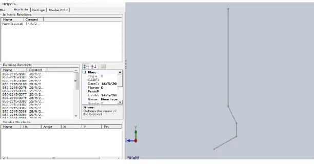
Indexing cases (brackets) here is similar to the one adopted in previous version, where the desired bracket sketch is drawn in CAD and all the data required is inherited into the system. The below figure-3.10 shows the place where the bracket is portrayed in system.
Figure 3.10 Import the new bracket from the sketch 3.3.2 Implemented concept in Retrieve
Case retrieval in our concept is based two aspects geometry and criteria chosen by designer. The following is the description of case retrieval procedure in our concept:
1. If the number of rear points of search brackets = the number of rear points of old brackets then the differences in distances of the rear points of search bracket and old bracket in both X, Y direction is adapted in algorithm mentioned above and the results are thus retrieved.
2. If the number of rear point of search bracket and old brackets are not equal then results are based on difference in the distance of each rear point of old bracket regarding X and Y axis.
3. Get the distance between the angle at bending point of search bracket and old bracket.
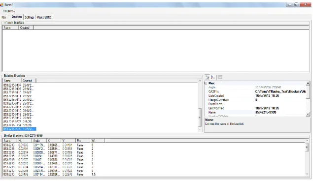
Then the system will retrieve the brackets through all of the constraints above and using the iterative closest point approach as mentioned before. After that the system will compute in order to get the similar brackets as shown in the figure-3.11.
Page 44 Figure 3.11 Similar brackets are provided from CBR algorithm
3.3.3 Implemented concept in Adapting case histories
In the adaptation or reuse step, there must be criteria established for defining a suitable bracket and make a group for seeking exactly same bracket from the library. As mentioned in theoretical background following the three general kinds of adaptation to define the proper brackets below:
1. Null adaptation means when the system try to seek the proper brackets and the result obtained exactly matches the old bracket (here it is only with respect to geometry).
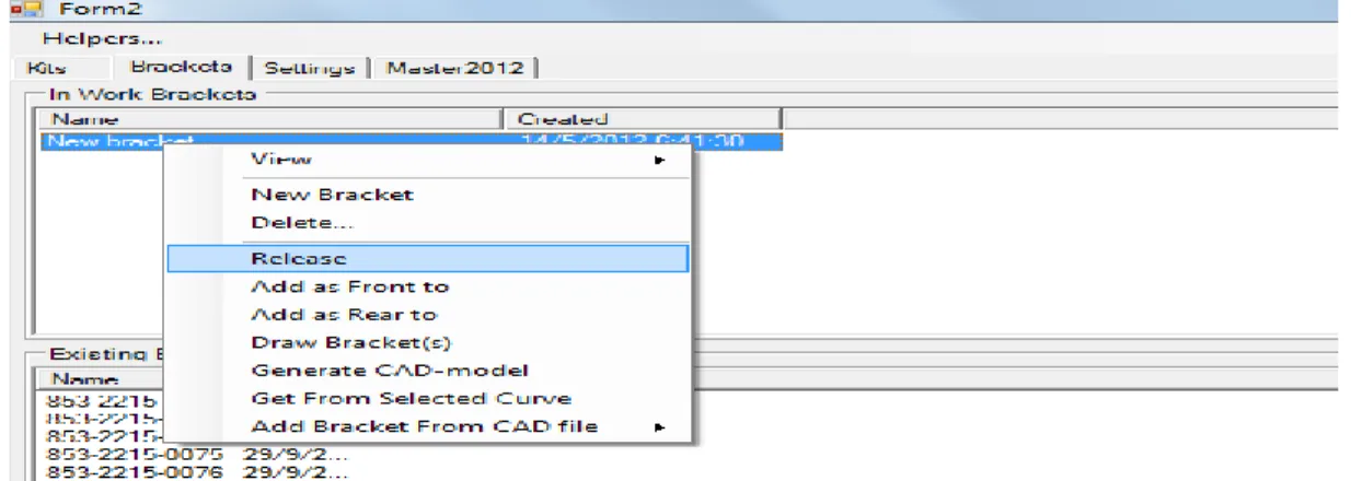
2. Topological adaptation segregates the brackets into groups which provide choices for selecting a group of brackets like bracket with pin, without pin, and wall thickness. And there also is “none” option provided just in case that engineer want to use all of the brackets in the library without considering any of the criteria as show in the figure-3.12
Figure 3.12 Used function for separated group of brackets
3. Parametric adaptation, in this case, there can be adjustment for parameter design such as changing the parameters(distance or angle) between the search bracket and old bracket to get suitable bracket as shown in the figure-3.13
Page 45 Figure 3.13 Comparing the search bracket with old bracket that are similar and only
adapt a bending point and angle of bracket
Moreover, we try to generate the best top three brackets from the three criteria that has been implemented from the previous system, our system, and another algorithm (three buttons in interface). Another algorithm is nothing but our concept with addition of more constraints. Here we consider the weight function with respect to the wall thickness of the bracket as:
1. If the wall thickness = 1.5 mm then the function should added more percentage of the weight at 5%
2. If the wall thickness = 2 mm then the function should added more percentage of the weight at 3%
3. If the wall thickness >2mm then the function should added more percentage of the weight at 2%
The above concept of assigning weights is not based on any data, it’s purely conceptual. According to information collected we have inferred that wall thickness of brackets has only two variants and thus we adopted the criteria. The weights are based on concept that wall thickness=1.5mm uses less material than the one with 2.0mm the weightage is more for first than for later one. Finally the weight for none is higher than other two because of increase in range of selection. Finally we have portrayed the results all different versions of results from different search algorithm into one list view as shown below in the figure-3.14.
Page 46 Figure 3.14 Top three brackets that are generated from the three criteria.
3.3.4 Implemented concept in Review
After the adaptation step has been done, next step is the review where search criteria brackets are compared with the results retrieve. Here in our concept the review part is taken up by the designer and if he finds the adapted result is good enough then it is stored in case library. If the results adapted is not suitable then the process repeats and will check for other similar brackets. The comparison is shown in figure 3.15 below
Figure 3.15 Comparing the search bracket with old brackets in case of the search bracket are not matched with old brackets
Page 47 3.3.5 Implemented concept in Retain
In this step, after all the process for search bracket has done then the new modified bracket will be used for the design task and added into the library of the bracket as shown step in the figure-3.16.
Figure 3.16 Collect the new design bracket in order to be the database for next search brackets
![Figure 0.1:The roof rack product is adapted to new car-models by changing the foot pad and the brackets components[3]](https://thumb-eu.123doks.com/thumbv2/5dokorg/4972922.136604/9.893.152.749.407.654/figure-roof-product-adapted-models-changing-brackets-components.webp)
![Figure 2.10 Similarity metric calculation chart between case#025 and new case [31]](https://thumb-eu.123doks.com/thumbv2/5dokorg/4972922.136604/26.893.137.764.103.553/figure-similarity-metric-calculation-chart-case-new-case.webp)