,
Implementation of Collection Tree Protocol over
WirelessHART Data-Link
Author: Kiran Kumar Koneri
EXAM WORK
2010
SUBJECT: Electrical Engineering with specialisation in
Embedded Systems
Postadress: Besöksadress: Telefon: Box 1026 Gjuterigatan 5 036-10 10 00 551 11 Jönköping
Implementation of Collection Tree Protocol over
WirelessHART Data-Link
Author: Kiran Kumar Koneri
This thesis work is performed at Jönköping University within the subject area of Electrical Engineering. This work is part of the Master’s Degree program with the specialization in Embedded Systems.
The author takes responsibility for opinions, conclusions and findings presented. Supervisor and Examiner: Professor Youzhi Xu
Scope: 30 credits (D-Level)
Date:
Archive Number:
Postadress: Besöksadress: Telefon: Box 1026 Gjuterigatan 5 036-10 10 00 551 11 Jönköping
Abstract
i
Abstract
Wireless Sensor Networks (WSNs) are ad-hoc wireless networks for small form-factor embedded nodes with limited memory, processing and energy resources. Certain applications, like industrial automation and real-time process monitoring requires time synchronized reliable network protocol. Current work for WSNs provides either time synchronized with low reliability (WirelessHART) or reliable network without time synchronization (Collection Tree Protocol). The Collection Tree Protocol (CTP) provides the reliability from 94.7% to 99.9% for CSMA-CA based MAC layer. This paper addresses channel hopping, a class of frequency diverse communication protocol in which subsequent packets are sent over different frequency channels. Channel hopping combats external interference and persistent multipath fading, two of the main causes of failure along a communication link. Channel hopping technique leads to a high reliable and efficient protocol which is specified by HART Communication Foundation and named as WirelessHART. WirelessHART Data-Link layer designed based on TDMA and CSMA-CA mechanism. By implementing the CTP over WirelessHART Data-Link layer, the reliability of the network protocol can be improved compare to actual CTP standard implementation. This thesis describes the design and implementation of Collection Tree Protocol over WirelessHART Data-Link layer. The implementation is done using TinyOS, nesC programming language using Crossbow TelosB CC2420 radio chip nodes. The results and experiments show the evaluation of the system prototype.
Key Words ii
Key Words
WSN WirelessHART Time Synchronization Channel Hopping Collection Tree Protocol ReliabilityAcknowledgement
iii
Acknowledgement
First of all, I would like to thank my Professor Youzhi Xu, who provided me an opportunity to do my master thesis in a very promising field of Wireless Sensor Networks. His great ability in grasping the research direction of wireless sensor network deeply inspired and educated me.
I would like to express my thanks to Ph.D candidate Wei Shen, who gave me his time, motivation, guidance and encouragement during my whole thesis study and lead me the way to finish.
I would like to say special thanks to our master’s program coordinator Alf Johansson and Professor Shashi Kumar, for being always helpful and giving all kinds of support during my master studies. I would like to thank Thomas Gustafson for delivering great and invaluable knowledge.
Last but not least, I am very thankful to my lovable and respectable parents Ashok Koneri and Uma Rani Koneri for their motivation during my difficult hours and support
throughout my life. Their love and supplications helped me in materializing my goals and in completing my thesis with success. I am also thankful to all my family members and friends for their support and encouragement throughout my studies.
Table of Contents iv
Table of Contents
Abstract ... i Key Words ... ii Acknowledgement ... iii List of figures ... viList of Tables ... vii
List of Abbreviations... viii
1. Introduction ... 1
1.1. Background ... 1
1.2. Purpose and Aim ... 2
1.3. Delimits ... 3
2. Technical Background ... 4
2.1. IEEE 802.15.4 ... 5
2.2. Introduction to WirelessHART ... 5
2.2.1. Physical Layer ... 7
2.2.2. Data – Link Layer ... 7
2.2.3. Network and Transport Layer ... 7
2.3. Introduction to Collection Tree Protocol ... 7
2.4. Related Work... 8
3. Methodology and Implementation process ... 9
3.1. Research Method ... 9
3.2. Implementation process ... 10
3.3. TinyOS v2.0 ... 10
4. WirelessHART ... 12
4.1. WirelessHART MAC protocol ... 12
4.1.1. The Data-Link packet (DLPDU) ... 12
Table of Contents
v
4.1.3. Shared slot ... 15
4.1.4. Communication Tables ... 16
4.2. Source Code – TSCH (Time Synchronized Channel Hoping) ... 17
4.2.1. Overview of TSCH ... 17
4.2.2. Packet structure ... 19
4.2.3. TSCH Wiring ... 20
4.2.4. TSCH message handling ... 23
5. Review of the Collection Tree Protocol (CTP) ... 26
5.1. CTP routing and Data Packets ... 26
5.1.1. Physical and MAC overhead ... 26
5.1.2. CTP Data Frame ... 26
5.1.3. CTP Routing Frame ... 27
5.1.4. Acknowledgements ... 28
5.2. Link Estimator module ... 28
5.3. Routing Engine module ... 28
5.3.1. Adaptive Beaconing ... 29
5.4. Forwarding Engine ... 29
5.4.1. Loop detection and handling ... 30
6. CTP over WirelessHART ... 31
6.1. CTP – TSCH packet structure ... 31
6.2. CTP – TSCH wiring and working ... 32
7. Experiments and Results ... 35
8. Conclusion and Future Work ... 38
References ... 39
Appendix 1: TSCH Data-Link layer component graph ... 41
Appendix 2: TSCHC component code ... 42
List of figures
vi
List of figures
Figure 2.1: A typical Multi-hop Wireless Sensor Network Architecture. ... 4
Figure 2.2: HART OSI 7-layer model [1] ... 6
Figure 2.3: The structure of a WirelessHART network ... 6
Figure 3.1: System development research method process ... 9
Figure 4.1: DLPDU structure [1] ... 13
Figure 4.2: A TDMA Slot and Superframe [1] ... 14
Figure 4.3: Channel Hoping [1] ... 15
Figure 4.4: Data-link table relationships [1] ... 17
Figure 4.5: Schedule of 4 nodes A, B, C, and D with a superframe length of 10 slots. ... 18
Figure 4.6: TSCH message structure ... 20
Figure 4.7: TSCH component wiring ... 22
Figure 4.8: TSCHQueueC component wiring ... 23
Figure 5.1: Structure of CTP’s data, routing and acknowledgement packets [20]. ... 26
Figure 5.2: Structure of CTP’s (a) data frame (b) routing frame (c) the header and footer of the LE ... 27
Figure 6.1: CTP-TSCH packet structure ... 32
Figure 6.2: CTP – TSCH component wiring. ... 33
Figure 7.1: Node 1 execution results ... 35
Figure 7.2: Node 2 execution results ... 36
Figure 7.3: The CtpP component’s internal wiring ... 37
List of Tables
vii
List of Tables
Table 4.1: Example BOCntr Selection Sets ... 16
Table 4.2: TSCH layer model ... 18
List of Abbreviations
viii
List of Abbreviations
ASN Absolute Slot NumberBOCntr Back-off Counter BOExp Back-off Exponent CTP Collection Tree Protocol DLL Data Link Layer
DLPDU Data Link Protocol Data Unit DSSS Direct Sequence Spread Spectrum ETX Expected transmissions
FCF Frame Control Field
FE Forwarding Engine or CTP Forwarding Engine LE Link Estimator
LR-WPANs Low-rate Wireless Personal Area Networks PAN Personal Area Network
PhPDU Physical Protocol Data Unit
RE Routing Engine or CTP Routing Engine TCP Transmission Control Protocol
TSCH Time Synchronized Channel Hopping TSMP Time Synchronized Mesh Protocol
Introduction
1
1. Introduction
Wireless Sensor Networks (WSNs) are gaining the ground in all sectors of life. WSNs offers a new approach to many environmental monitoring and event detection applications such as military applications, industrial process monitoring and control, healthcare applications, home automation, agriculture and habitant monitoring [5] [6] [7]. Monitoring seems to be the key word. The WSNs are made of nodes, which could be from few hundreds to even thousands. Each Node has typically several equipments such as radio transceiver, microcontroller, sensor(s), and power supply which have been integrated all on a centimetre or even millimetre sized circuit board. The power supply is off-grid, for example batteries, solar power, energy harvesting. Once deployed, sensor nodes can capture data about some physical quantity, like temperature, atmospheric pressure or a pollutant concentration.
This paper includes one of these research application areas which is an industrial automation using WSNs. Several industrial organizations, such as ISA, HART and IEEE 802.15.4e have been chasing the application of wireless technology in industrial process.
In the future chapters, it is discussed that the deployment of a well defined and standardized routing protocol for the industrial applications, also the implementation of proposed protocol stack is discussed.
1.1. Background
Sensor readings are then usually reported to a central server, also called the sink node, where they are further processed according to the application requirements. To report their readings to one or more data collectors, sensor nodes communicate through their integrated radio-transceivers and collaboratively build an ad-hoc, possibly multi-hop relay network. An efficient, reliable, robustness and time synchronized data transmission is essential for WSNs employed in scenarios. The WSN research community proposed algorithms and protocol aiming at guaranteeing efficient and reliable data collection. In particular, The Collection Tree Protocol (CTP) provides for “best-effort anycast datagram communication to one of the collection roots in a network” [8, 9, 10]. CTP is widely regarded as a reference protocol for performing data collection in WSNs. CTP is designed based on Carrier Sense Multiple Access – Collision Avoidance (CSMA – CA) which not suitable for industrial applications. WirelessHART is designed especially for process measurement and control applications. WirelessHART is Time Division Multiple Access (TDMA) based wireless technology which supports for channel hoping and time synchronization of the network [1]. Channel hoping is discussed more in chapter 2 and chapter 4. By deploying the deploying the CTP routing protocol with the WirelessHART Data-link layer, the time synchronized and more reliable than actual CTP protocol can be achieved.
Introduction
2
1.2. Purpose and Aim
This master thesis is to implement a well-defined and standardized Collection Tree Protocol over WirelessHART data link layer to achieve more reliability and efficiency compared to original CTP, also to make it possible to use CTP in the industrial applications.
From the industrial point of view, the requirements are:
1. For the process and real time based control automation, the protocol stack must be time synchronized.
2. The reliability of the protocol should be improved as compared to earlier implementations.
3. The protocol should deliver with minimum amount of transmission across the network, i.e. efficiency.
4. The protocol should be able to operate without configuration in a wide area of network conditions, topologies, workloads, and environment, i.e. robustness.
5. The protocol should be hardware independent.
To achieve these goals the necessary functional requirements are:
1. The protocol’s Data Link layer must be a Time Division Multiple Access (TDMA) based mechanism.
2. The possible improvement of reliability of the network can be achieved by using channel hopping technique.
3. The efficiency and robustness can be achieved by choosing appropriate routing protocol and link estimator.
4. Interfacing must be done according to functional requirements of the chosen Data-link and Network layer.
5. The chosen Data-link and Network layers must support their packet formats and hardware independence.
The master thesis tasks include:
1. Analyzing and providing a detailed explanation of the design and implementation of chosen Network and Data-Link layers.
2. Implementing the Network layer on top of the TDMA based and channel hopping Data-Link layer.
3. Design and implementation of the Interface between the Network and Data-Link layer according to the superframe structure.
4. Design and implementation of Application layer on top of the Network layer. 5. Testing and evaluating the basic functionality of the new proposed system protocol.
Introduction
3
Finally, provide a detailed explanation report of the proposed protocol implementations to be more helpful for the researchers.
1.3. Delimits
This master thesis and time synchronized CTP protocol project is a part of WirelessHART research working group of the Jönköping University. This research is still in the prototype stage; all the experiments fulfil the basic functionality of the system. This research does not include implementation of superframe as it is required for the Network Layer protocol, also the superframe design depends on the application. Due to limited time and resources this document does not provide reliability improvement exact experimental results.
Theoretical Background
2. Technical Background
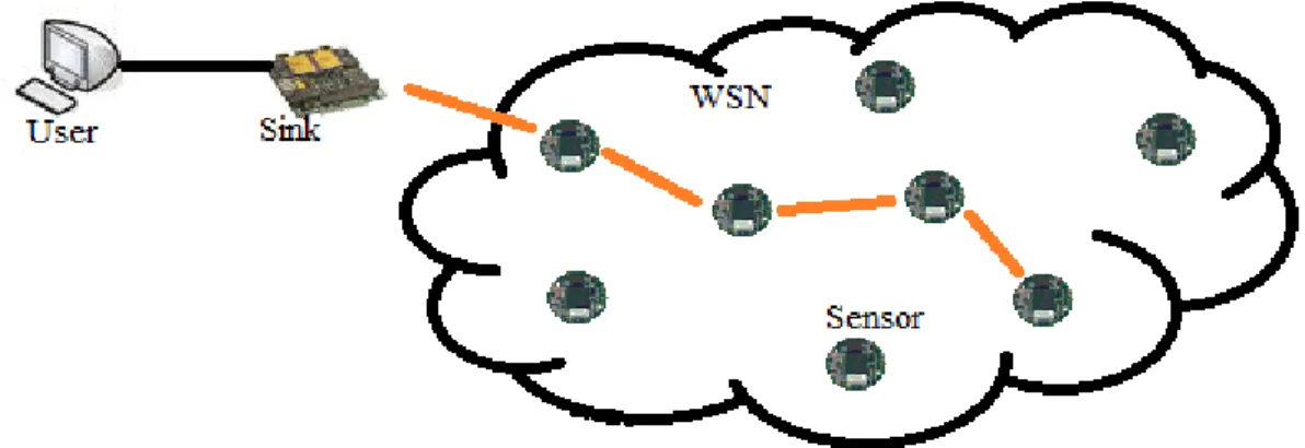
A Wireless Sensor Network (WSN) consists of spatially distributed individual sensor nodes which work together to monitor physical and environment parameters, and transmit monitor result to base station. One of the common use structures of WSN is showed in figure 2.1. Sensor nodes are deployed into a monitoring region, and constitute a wireless ad-hoc network automatically. Sensor nodes support multi-hop algorithm, and together, they forward data packets to the base station. Some of the sensor nodes in network may be fixed at a certain position in order to monitor some unmoved parameters at its appropriate place.
Figure 2.1: A typical Multi-hop Wireless Sensor Network Architecture.
The environment can be either the physical world or an information technology framework. That is why WSN can be used in many industrial and civilian applications, including industrial process monitoring and control, healthcare applications, habitat monitoring, home automation and many others [5] [6] [7].
Sensor node typically consists of one or more sensors, radio transceiver, a small microcontroller, and an energy source, usually a battery. Its size can be as small as a grain and its price can down to a penny.
The main features and challenges of WSN can be summarized as: • Low cost devices
• Energy-efficient devices • End-to-end quality of service
• Seamless operation under context changes • Secure operation
• Large scale of deployment • Mobility of nodes
Theoretical Background
5
Here in this thesis, we use WSN, with self-development standard, for industrial automation applications.
2.1. IEEE 802.15.4
IEEE 802.15.4 – 2006 is a standard which specifies the physical layer and media access control (MAC) for low-rate wireless personal area networks (LR-WPANs). It is revised version released in September 2006. It is maintained by the IEEE 802.15 working group. The targeted application for IEEE 802.15.4 is focus on low-cost, low-speed areas like wireless sensor network, home network, industrial control, remote monitor, building automation, and so on. Beside, these applications usually has low bitrates (up to some few hundreds of kbps), flexible, ad-hoc self-organize, not too stringent delay guarantees, and sometime low power consumption requirement.
The physical layer, based on direct sequence spread spectrum (DSSS), offers bitrates of 20 kbps (a single channel in the frequency range 868-868.6 MHz), 40 kbps (ten channels in the range between 905 and 928 MHz) and 250 kbps (16 channels in the 2.4 GHz ISM band between 2.4 and 2.485 GHz with 5- MHz spacing between the center frequencies). Even there are 27 channels available, but the MAC protocol use only one of these channels at a time. This standard is not a multichannel protocol [4].
ZigBee, WirelessHART, and MiWi specification use the services offered by IEEE 802.15.4 and attempts to offer a complete networking solution by developing the upper layers which are not covered by the standard. Our designed specification also follows this standard (using 2.4 GHZ ISM band in physical layer and super frame structure with CSMA/CA protocol in MAC layer) and adds network construction (mesh networks), security, application services, and more.
2.2. Introduction to WirelessHART
WirelessHART is a secure and Time Division Multiple Access (TDMA) based wireless mesh networking technology operating in the 2.4Ghz ISM band. WirelessHART is an optional HART Physical Layer that provides a low cost, relatively low speed(e.g., compared to IEEE 802.11g) wireless connection to HART-enabled devices. TDMA is used to schedule the communication of the various devices. All communication is performed within a designated time slot of 10ms. A series of time slots form a superframe. WirelessHART also enables channel hopping to avoid interference and reduce multi-path fading effects. One or more sources and one or more destination devices may be scheduled to communicate in a given slot. The slot may be dedicated to communication from a single source device or a slot may support shared communication.
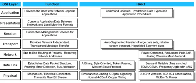
HART is loosely organized around the ISO/OSI 7-layer model for communication protocols (see Figure 2.2) [3]. With the introduction of wireless technology to HART, two Data-Link layers are supported: the token-passing and TDMA. Both support the common HART Application layer.
Theoretical Background
Figure 2.2: HART OSI 7-layer model [1]
All the communications of the WirelessHART network pass through the gateway. Consequently, the gateway must route packets to the specified destination (network device, host application or network manager). The gateway uses standard HART commands to communicate with network devices and host applications. The plant automation network could be a TCP based network, a remote IO system, or a bus such as PROFIBUS DP. The network manager creates an initial superframe and configures a Gateway. A detailed description of the components of a WirelessHART network is given in [2]. The structure of WirelessHART network is shown in the figure.
Figure 2.3: The structure of a WirelessHART network
Theoretical Background
7
2.2.1. Physical Layer
TheWirelessHART physical layer is based mostly on the IEEE STD 802.15.4-2006 2.4GHz DSSS physical layer [5]. This layer defines radio characteristics, such as the signalling method, signal strength, and device sensitivity. Just as IEEE 802.15.4 [5], WirelessHART operates in the 2400-2483.5MHz license-free ISM band with a data rate of up to 250 kbits/s. Its channels are numbered from 11 to 26, with a 5MHz gap between two adjacent channels.
2.2.2. Data – Link Layer
One distinct feature of WirelessHART is the time synchronized data link layer. WirelessHART defines a strict 10ms time slot and utilizes TDMA technology to provide collision free and deterministic communications. The concept of superframe is introduced to group a sequence of consecutive time slots. Note a superframe is periodical, with the total length of the member slots as the period. All superframes in a WirelessHART network start from the ASN (absolution slot number) 0, the time when the network is first created. Each superframe then repeats itself along the time based on its period.
2.2.3. Network and Transport Layer
The network layer and transport layer cooperate to provide secure and reliable end-to-end communication for network devices. As shown in Figure 4, the basic elements of a typical WirelessHART network include: (1) Field Devices that are attached to the plant process, (2) Handheld which is a portable WirelessHART-enabled computer used to configure devices, run diagnostics, and perform calibrations, (3) A gateway that connects host applications with field devices, and (4) A network manager that is responsible for configuring the network, scheduling and managing communication between WirelessHART devices.
The WirelessHART standard does not give any specification concerning about a particular scheduling algorithm to be used in a WirelessHART network.
2.3. Introduction to Collection Tree Protocol
The Collection Tree Protocol (CTP) is a simple tree based protocol proposed for collection of data from sensor nodes into the root node. All the communication is many to- one or one-to-many. The nodes form a set of routing trees, whereas multiple root nodes are allowed. The CTP is address-free protocol. The sensors send data packets to the next hop whereas routes are based on a routing gradient. The protocol has the following properties [9]:
• CTP assumes that it has link quality estimates of some nearby neighbours. These provide an estimate of the number and quality of transmissions it takes for the node to send a unicast packet whose acknowledgment is successfully received.
• CTP has several mechanisms to improve delivery reliability, but it does not promise 100 % reliable delivery. This has been evaluated on 12 test beds using 20 to 310 range sizes of nodes. It is best effort, but a best effort that tries very hard.
Theoretical Background
8
• CTP is designed for relatively low traffic rates. Bandwidth-consuming systems might benefit from a different protocol, which can, for example, pack multiple small frames into a single data-link packet.
• CTP uses expected transmissions (ETX) as its routing gradient. A root has an ETX of 0. The ETX of a node is the ETX of its parent plus the ETX of its link to its parent. If several routes are valid, CTP should choose the one with the lowest ETX value. This protocol was proposed for data gathering with low energy demands. Routes established during node deployment are not updated periodically, but only if inconsistency in the network topology is detected. A loop is detected when node chooses a route with gradient value significantly higher than its old one. This may be caused by losing connectivity with the current parent node. The CTP offers two solutions: (1) beacon frame and (2) ignoring routes with an ETX higher than a reasonable constant. The protocol provides also a handle for packet duplication. When a duplicate instance of a packet is detected during its forwarding, it is dropped.
The CTP is designed for minimum power consumed consumer products. It has no time synchronization mechanism for the industrial process automation. Also the reliability can be improved using channel hopping technique. Our aim is to propose such improvement of CTP that offers high reliability compare to original CTP and to be a time synchronized network.
2.4. Related Work
Time Synchronized Mesh Protocol (TSMP) [12] was designed to improve reliability. TSMP employs frequency hopping: different links use different frequency channels and the same link hops during its lifetime across different channels. This reduces the impact of narrow-band interference and persistent multipath fading. [13] presents experimental results in which 44 nodes run TSMP for 26 days in a printing facility. The authors shows how channel hopping combined with a retransmission policy. TSMP uses a central coordinator which retrieves the list of nodes, their neighbours and their traffic requirements. This allows it to construct a schedule which is then communicated back to the network.
Critical applications require reliable solutions, and channel hopping is one answer to this need. With the success of proprietary solutions such as TSMP, standardization bodies have been working on similar solutions.
TSMP and WirelessHART uses central controller to schedule communication. The reliability is increased by having each node maintain connectivity to at least two parent nodes in the routing graph, enabling the network to resist link failures. Another industrial wireless standardization body is the ISA100 Wireless Compliance Institute. Their latest standard
ISA100a [14] is similar in essence to TSMP or WirelessHART, yet features interesting channel hopping mechanisms.
Method and Implementation
3. Methodology and Implementation process
3.1. Research Method
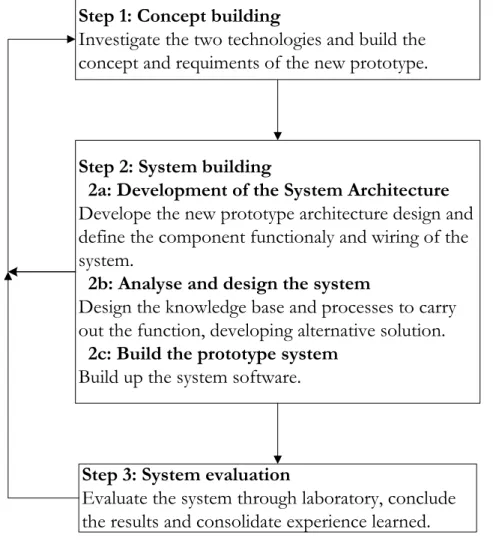
This thesis design follows the system development research method [15]. The systems development approach denotes a way to perform research through exploration and integration of available technologies to produce an artefact, system or system prototype. System development focuses on theory testing more than theory building, which allows a smooth propagation from development to evaluation. Based on these, system development research method is suitable for this research work. This system development research uses two available technologies and generated a new concept prototype by integrating and evaluating. The implementation of CTP over WirelessHART protocol research process illustrated in figure 3.1,
Step 1: Concept building
Investigate the two technologies and build the concept and requiments of the new prototype.
Step 2: System building
2a: Development of the System Architecture
Develope the new prototype architecture design and define the component functionaly and wiring of the system.
2b: Analyse and design the system
Design the knowledge base and processes to carry out the function, developing alternative solution.
2c: Build the prototype system
Build up the system software.
Step 3: System evaluation
Evaluate the system through laboratory, conclude the results and consolidate experience learned.
Figure 3.1: System development research method process
Method and Implementation
10
3.2. Implementation process
For the implementation of reliable time synchronized network protocol we use CTP as the underlying routing protocol. The original implementation of the CTP is not time synchronized and does not support channel hoping in the network. To overcome this problem, we are using WirelessHART MAC – sublayer as CTP’s MAC layer. WirelessHART standard supports time synchronization and channel hopping of the network.
For the implementation of our reliable time synchronized network protocol we are using CTP and WirelessHART protocols. The original implementation of CTP is designed based on IEEE 802.15.4 – 2006 MAC and Physical Layers. IEEE 802.15.4 – 2006 MAC sub-layer employs the CSMA – CA mechanism. CSMA – CA does not support time synchronization and channel hoping. So that we are using WirelessHART protocol standard which is based on TDMA and CSMA – CA (for shared slot) that has been discussed in chapter 2. All the improvements and additions are discussed in remainder of this chapter. The implementation is done in TinyOS, which is commonly used operating system in WSNs. We will start the detailed explanations with TSCH WirelessHART MAC sub – layer, CTP routing protocol and implementation of CTP over WirelessHART.
3.3. TinyOS v2.0
TinyOS is an open source project with a large number of research universities and companies contribute to [16]. TinyOS is a lightweight operating system specially designed for low power wireless sensors. TinyOS differs from other operating systems in that its design focus is on ultra low power microcontrollers’ motes rather than full fledged processors. TinyOS provides a component model, concurrent execution model and application programming interfaces (APIs) which enables rapid innovation and implementation while minimizing code size as required by severe memory constraints in sensor networks. TinyOS’s event – driven execution model and fine grained power management allows the scheduling flexibility which is necessary for the unpredictable nature of wireless communication and physical world interfaces. Furthermore to understand clearly about the thesis’s software implementation part, we will briefly discuss about components, interfaces and wiring.
TinyOS applications and systems as well as the OS itself are written in nesC language which is a C dialect. The three essential differences between the C and nesC are components, interfaces and wiring. NesC’s components provide a more systematic approach for organizing a program’s elements. A component (module or configuration) groups related functionality (timer, sensor, system boot) into a single unit in a way that is very similar to the object – oriented language.
NesC’s interfaces are very similar to Java interfaces, with the addition of a command and event keyword to distinguish request from call-backs. Interfaces bring further request to components which are normally specified in terms of the set of interfaces such as Boot, SplitControl, AMSend that they provide and use.
Method and Implementation
11
Instead of connect declarations to definitions with the same name, nesC programs are built out of components that are connected (“wired”) by explicit program statements. For example,
HelloworldC.Boot -> MainC.Boot;
In this command line, HelloworldC is an application’s component, MainC is TinyOS’s system boot component. This line says that HelloworldC component’s Boot interface using MainC component’s Boot interface. That means HelloworldC.Boot is an user and MainC.Boot is a provider. Furthermore explanation, when MainC has finished booting the system it signals the booted event of its Boot interface, which is connected by the wiring to the booted event in HelloworldC.
WirelessHART
12
4. WirelessHART
In this thesis TinyOS based TSCH has been used for the implementation which is a brief version of WirelssHART protocol. This section includes the description of technical characteristics of the WirelessHART. Furthermore, the structure of the MAC and communication protocol will be described. The reader familiar with these topics can easily skip these sections and proceed with section 4.2. In section 4.2 the code analysis of the TSCH is described.
4.1. WirelessHART MAC protocol
The main purposes of the WirelessHART MAC (Medium Access Control) protocol are: • Superframe slot synchronization
• Identification of nodes that need to access the medium • Propagation of messages received from Network Layer • To listen for packets being propagated from neighbours
The MAC sub-layer is responsible for propagating the Data-Link packets (DLPDU) across a link. To be able to propagate the node includes, firstly the table of neighbours, superframe, links and graphs that configure the communication between the device and its neighbour. These tables are normally populated by the network manager. The neighbour table consists of neighbour nodes as discovered. Second, the link scheduler that evaluates the device tables and chooses the next slot to be serviced by listening for a packet or by sending a packet. Third, state machines that control the propagation of the packets through the MAC sub-layer. MAC operation consists of schedule maintenance and service slots. MAC operation is fundamentally event driven and responds to service primitive invocations and the start of slots needing servicing.
4.1.1. The Data-Link packet (DLPDU)
The format of the Data-Link packet (DLPDU) has shown in the figure 4.1. Each DLPDU consist of the following fields:
• A single byte set to 0x41 • A 1-byte address specifier • The 1-byte Sequence Number • The 2-byte Network ID
• Destination and Source addresses either 2 or 8-byte long • A 1-byte DLPDU specifier
• The DLL payload
WirelessHART • A 2-byte ITU-T CRC 16
Figure 4.1: DLPDU structure [1]
Figure 4.1 shows the basic PhPDU and DLPDU structure. The total length of the packet is 127 bytes.
There are four types of DLPDU Wireless HART. The least significant 3 bits of DLPDU indicate the type of DLPDU being communicated and the purpose of the (optional) DLL payload. There are five DLPDU types [1]:
• DATA DLPDU: The Source Address and Destination Address field of this DLPDU type is regarded the Network Layer of both source and destination devices. The packet payload generated from the Network Layer of hopes source device and is passed to the destination devices Network Layer. This type of packet is containing network and device data in transit to their final destination.
• Keep-Alive DLPDU: it used for network maintenance, for network time synchronization, for assess communication with a neighbour (confirm connectivity) and for neighbour discovery. This packets payload is empty (equal to zero). This packet is not broadcast since it would be sent to specific neighbour.
• Advertise DLPDU: It is used to invite new devices into the network. When a device wishes to join a network, it listens to Advertise DLPDU packet and then uses the information in this packet to synchronize with the network and initiate the join process. The Advertise DLPDU packets contain network information, Absolute Slot Number (ASN), join control information and the security levels. The Advertise DLPDU Destination Address field should be broadcast.
• Disconnect DLPDU: It is used to inform the neighbouring devices that the device is leaving the network. The payload of this packet is empty.
• ACK DLPDU: It is transmitted by a device in response to receipt of non broadcast and non-ACK DLPDU.
WirelessHART
4.1.2. TDMA overview
WirelessHART uses TDMA topology and channel hopping to control access to the network. TDMA is a widely used Medium Access Control technique that provides collision free, deterministic communications. It uses time slots where communications between devices occur. A series of time slots form a TDMA superframe as shown in the figure 4.2.
Figure 4.2: A TDMA Slot and Superframe [1]
All devices must support multiple superframes. Slot sizes and the superframe length (in number of slots) are fixed and form a network cycle with a fixed repetition rate. Superframes are repeated continuously. For successful and efficient TDMA communications, synchronization of clocks between devices in the network is critical. Consequently, tolerances on time keeping and time synchronization mechanisms are specified to ensure network-wide device clock synchronization. It is imperative that devices know when the start of a slot occurs. Within the slot, transmission of the source message starts at a specified channel. Since there is a tolerance on clocks, the receiver must start to listen before the ideal transmission start time and continue listening after the ideal time. Once the transmission is complete, the communication direction is reversed and the destination device indicates, by transmitting as ACK, whether it received the source device DLPDU successfully or with a specific class of detected errors. To enhance reliability, channel hopping is combined with TDMA. Channel hopping provides frequency diversity, which can avoid interference and reduce multi-path fading effects.
WirelessHART
Figure 4.3: Channel Hoping [1]
Communicating devices are assigned to a superframe, slot and channel offset. This forms a communications link between communicating devices.
4.1.3. Shared slot
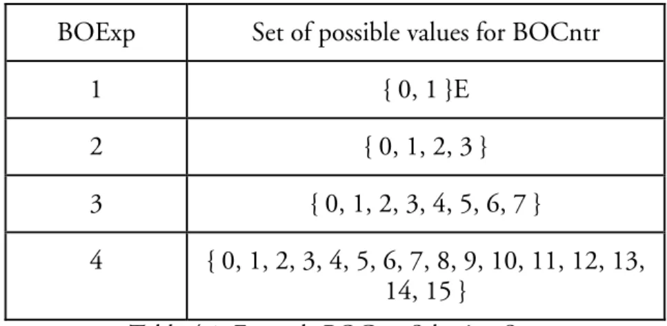
It is important to know the purpose and functionality of shared slot for the WirelessHART. Shared slots are assigned to many source devices of which may attempt to convey a packet within that slot and channel. Consequently, collisions may occur within a shared slot. If a collision occurs, the destination device will not be able to successfully receive any source’s transmission and will not produce an acknowledgement to any of them. To reduce the probability of repeated collisions, source devices shall use random back-off delay when their transmission in a shared slot is not acknowledged (i.e., no ACK is received by the source device).
A device shall maintain two variables for each neighbour. Those are Back-off Exponent (BOExp) and Back-off Counter (BOCntr). Both of these variables are initialized to 0. When a transaction in shared slot fails the random back-off period is calculated based on the BOExp. For each unsuccessful attempt by the source device in a shared slot the BOExp is incremented and sequential set of numbers calculated. The set of numbers consists of the whole numbers { 0, 1, ..L } where
L = (2 ^ BOExp - 1) --- (eq. 4.1) 15
WirelessHART
16
BOExp Set of possible values for BOCntr
1 { 0, 1 }E
2 { 0, 1, 2, 3 }
3 { 0, 1, 2, 3, 4, 5, 6, 7 }
4 { 0, 1, 2, 3, 4, 5, 6, 7, 8, 9, 10, 11, 12, 13, 14, 15 }
Table 4.1: Example BOCntr Selection Sets
A sample random back-off sets for BOExp values of one to four are shown in table 4.1. From this set calculated based on the BOExp, a random value for the BOCntr is selected. For each subsequent shared link to that neighbour, the BOCntr must be decremented. Only when the corresponding BOCntr is zero can the source device attempt a transmission in a shared slot. The value of BOExp shall not exceed that of MAXBackoofExponent.
4.1.4. Communication Tables
WirelessHART maintains a series of tables that control the communication performed by the device. The communication table activity includes:
• Superframe and link tables: Multiple superframes may be configured by the network manager. Multiple links within a superframe are configured to specify communica-tion with a specific neighbour or broadcast communicacommunica-tions to all listening to the link • The neighbour table: The neighbour table is a list of all devices that the device may be
able to communicate with.
• The graph table: Graphs are used to route messages from their source to their destination. The communication tables and the relationships between them are shown in figure 4.4.
WirelessHART
Figure 4.4: Data-link table relationships [1]
4.2. Source Code – TSCH (Time Synchronized Channel
Hoping)
This section discusses the implementation of WirelessHART in the TinyOS platform. In this thesis we are using TSCH (Time synchronized Channel Hoping) as a source code for WirelessHART prototype [17]. TSCH’s MAC-sublayer has been developed based on WirelessHART and it has similar properties such as Time synchronization, Channel Hoping and Reservation. TSCH is an open source and it has been developed by Dust Networks and Berkeley Sensor & Actuator Center group of University of California [17]. In this thesis TSCH’s stack components Physical, MAC sub – layer and Application layer has been used. That means, the present used TSCH code is a star based network protocol. Furthermore, the detailed explanations of TSCH has discussed in below sub sections.
4.2.1. Overview of TSCH
TSCH has two main functions; those are Channel Hoping and Reservation. As explained in section 4.1.2, Channel hoping is nothing but by pseudo randomly changing the channel between the packets in order to reduce the narrowband interfaces. Communication can occur in all available frequency channels which increases reliability when compare to single channel solution. Reservation is a distributed reservation mechanism which enables collision – free communication to achieve high data rates flow isolation under strict power constraints. The TSCH stack layer in the ISO/OSI 7-layer model is shown in the table 4.2.
WirelessHART
18
ISO/OSI Layer Standard
Application Application Data Link WirelessHART
Physical IEEE 802.15.4
Table 4.2: TSCH layer model
TSCH requires synchronization. Time is divided into slots is specified as an Absolute Slot Number (ASN). ASN is incremented at each slot and shared by all nodes. At each new slot, the frequency to be used is calculated using the equation below. ChannelOffset is a number between 0 and 15 which is assigned to each slot during reservation. 100 slots form a superframe which repeats over time.
Frequency = (ASN + channelOffset) % 16 (eq. 4.2)
For example, during reservation, one of the slots in the superframe of node A may be reserved for sending data to node B at a given channelOffset. In every 100 slots, node A can thus send to node B at a frequency calculated with the equation 4.2. The key is that ASN is incremented at each slot, so subsequent packets are sent at different frequencies [17].
Reservation: Reservation mechanism is very similar to the WirelessHART’s superframe & link tables of communication table (Section 4.1.4). The main purpose of the reservation mechanism is for nodes to agree upon a collision free schedule. The figure 4.5 shows an example slot schedule for 4 nodes A, B, C and D with a superframe length of 10 slots. Each cell of the superframe either not used or is one of the following states.
Ch5 node BRes
Ch4 DATA B to A Ch3 node DRes DATA C to A Ch2 node CRes Ch1 node ARes DATA D to C
Ch0 ADV
T1 T2 T3 T4 T5 T6 T7 T8 T9 T10
Figure 4.5: Schedule of 4 nodes A, B, C, and D with a superframe length of 10 slots.
• DATA cells • RES cells
WirelessHART
19 • ADV cell
DATA cells are used to send data packet from given node to another. RES cells are used to exchange information for DATA cell reservation. Each node has one RES cell during which it listens. It announces the slot and channelOffset of its RES cell to its neighbours using advertisement messages. The ADV cell is shared by all nodes and is used for receiving and transmitting advertisement messages to allow for new nodes to join the network [17].
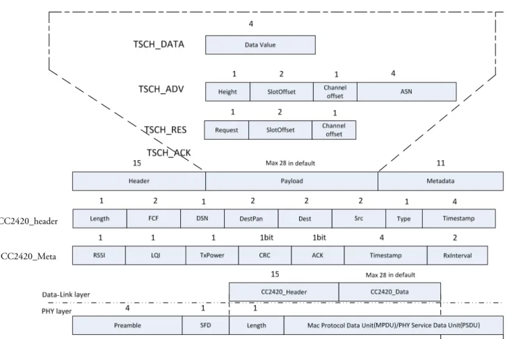
4.2.2. Packet structure
Figure 4.6 gives a graphical representation of TSCH command and data packets of Data-Link layer. ACK, Advertise, Keep-Alive and Reservation packets generated and consumed by Data-Link Layers. These packets are not propagated to/from the upper layer. In other words, these are a DLL command packets originated within the source Data-Link and consumed by a neighbouring Data-Link.
CC2420 header contains length, frame control field (FCF), destination sequence number (DSN), destination PAN (DestPAN) ID, destination (Dest), source, type and timestamp. Length field is size of 1 byte which contains except the Length field size, total length of the header and payload of the packet. The FCF is defined the value of frame control. DSN contains a number incremented for each packet sent by a particular node. This is used in acknowledging that packet, and also filtering out duplicate packets. DestPAN is a 2 bytes ID, which is used if the network is sitting side by side with another TinyOS network we can distinguish it from others with this ID. Dest contains the destination address of the packet. 0xFFFF is the broadcast address. Src is the local node ID that generates this message (Source ID). Type field is used to distinguish between the packets of different types. TimeStamp filed consist of node’s global time when the message is about to send. The CC2420 header introduces 15 bytes of overhead per message.
The metadata contains information about the packet that is used by the radio stack. It is not transmitted as part of the packet, but rather contains information about the packet. The metadata fields are all 0's at boot initialization.
WirelessHART
CC2420_header
CC2420_Meta
Figure 4.6: TSCH message structure
Basically, TSCH has 4 types of packets: ADV, DATA, RES and ACK packets. An Advertise packet contains height, SlotOffset, ChannelOffset and absolute slot number (ASN). Height field contains the value of hop distance from the root node device.
A data packet contains data in transit to a final destination device. The packet payload in these data packets originates from the Application layer of this source device and is passed to the destination device’s Application layer. In this thesis the data is an integer counter which is transferred to the root. Keep-Alive is command packet and it is a DATA type which does not contain any data.
A RES packet contains request type, slotOffset and channel offset. Request type has four kinds of commands: Request cell (RES_REQ_CELL), Free cell (RES_FREE_CELL), Success (REQ_SUCCESS) and Fail (RES_FAIL). These request commands are used to update the device’s superframe cell. Finally, the ACK packet does not contain any payload.
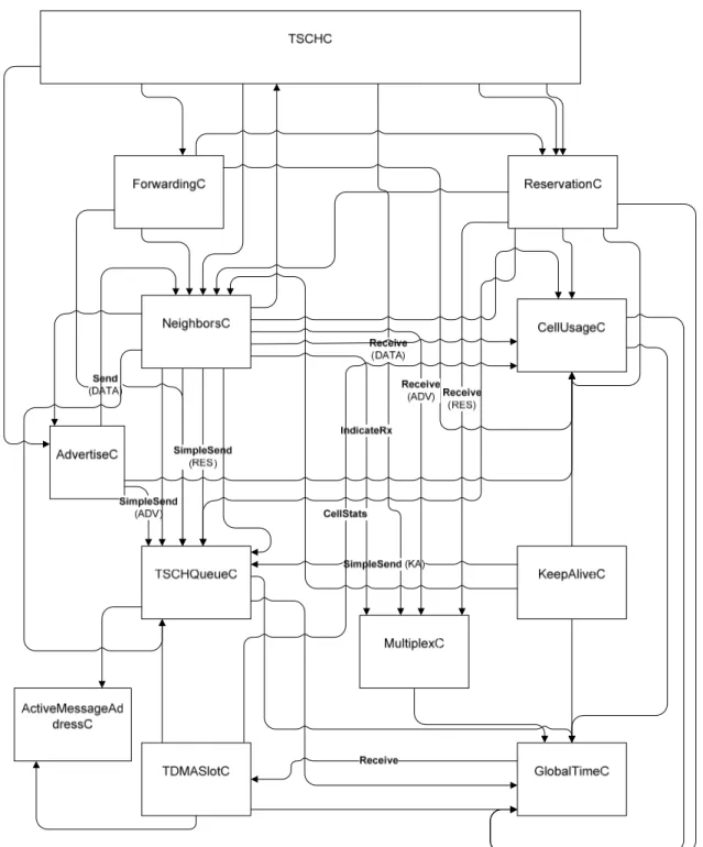
4.2.3. TSCH Wiring
This section covers the brief explanations about neighbours, cell usage, global time and TSCH queue components. Later how these components are wired together for the complete data-link operation has explained. As explained in WirelessHART section 4.1.4, neighbour
WirelessHART
21
component is used to maintain the table list of neighbour devices and their details such as ID, height, link quality, confidence, number of sent, number of successful sent, and last heard timestamp. Each device maintains the record maximum of 10 neighbours.
Cell is the combination of a slot and a channel offsets in a superframe. The length of the superframe (cell-frame) is 101. Cell usage component is similar function as WirelessHART’s Link table which maintains the record such as, for which neighbour what type of cell has been allotted. There are 7 types of cell: no use, RxData, TxData, ADV, RxReservation, TxReservation and Reserved. It is used to get the cell usage details also to set and remove the cell configurations. Setting and removing the cell usage done using neighbour and reservation components. Cellusage component provides the cell usage details mostly to the every component of TSCH stack as shown in the figure 4.7.
It is important to maintain the global time in the network for the slot synchronization. So that, two nodes can be ready to communicate at the same time with collision-free. Network manager provides the global time to the slave nodes of network. For the network synchronization, GlobalTime component provides global time, local time, absolute slot number (ASN) and global synchronization using GlobalTime.nc and GlobalSynch.nc interfaces. Furthermore, GlobalTime component uses receive event from the TDMASlot component to update the global time and to be synchronized.
WirelessHART
Figure 4.7: TSCH component wiring
TSCHQueue component maintains a pool of messages which are about to send. Figure 4.8, is an extracted component wiring from TSCH wiring (figure 4.7). Globaltime interface is used to assign the ASN value in the advertise packet field. GlobalSynch interface is used to check the network synchronization of the node. As shown in figure 4.7, all the 4 types of messages get pooled in this component. As the name mentions DeQueue interface performs de-queuing of messages from TSCHQueueC component to TDMASlotC component.
WirelessHART
Figure 4.8: TSCHQueueC component wiring 4.2.4. TSCH message handling
Advertise: As briefly explained in section 4.1.1, ADV packet is used to invite new devices into the network. When an unknown device about to join the network, it listens the advertisement packet and uses the packet fields to initiate join process to be synchronized. As mentioned in section 4.1.1, ADV packet is a broadcasting packet. A broadcasting packet is transferred only in shared slot using CSMA – CA mechanism. As shown in the figure 4.5, the superframe’s first slot and first channel offset is a shared slot with the type of ADV cell. Advertise component is responsible for generating ADV packet using random one-shot timer. Since all the nodes cannot send ADV packet at the same time. Advertise packet structure is assigned in TSCH.h header file which includes height, slotOffset, channelOffset and asn. In thesis TSCH is a star based network, so that the height of root node will be 0 and for the non root single hop node it is 1. Using cellUsageGet.nc interface, the values of slotOffset and channelOffset can be retrieved from the CellUsage component and assign them into the ADV packet respective fields. These values are used to represent the superframe reservation updates to the whole network devices. So that other components can request for reservation process on other than these slot and channel offsets.
From the Advertise component ADV packet is sent to the TSCHqueue component message queue. Before de-queuing from queue of messages, TSCHqueue component assigns updated absolute slot number (ASN) to ADV packet field using GlobalTime.nc interface. As the name itself represents ASN is the value of superframe’s slot number which is sent to the entire network for the better slot synchronization of the network.
After reservation updates, when a node receives an Advertise packet from the root node that means these nodes are in synchronization. From the receiving end, TDMASlot component will signal all the received packets to the GlobalTime component for the synchronization updates. Using ADV packet GlobalTime component handles the synchronization of the slave node to the root node. After updates, GlobalTime component signals any type of packet to the Multiplexer component. As shown in the figure 4.7, Multiplexer component is used to signal the received packet to the respective component according to the type of
WirelessHART
24
received packet. ADV packet is signalled to the Neighbour component for the neighbour table updates.
Reservation: As explained in section 4.2.1, the reservation process is one of the important tasks for the collision free packet transfer. This sub section explains how these reservation command packets are handled for the collision free packet transfer. When a node is about to send a data packet to any other node, it is obvious that the sender node requests for the reservation update first. In this TSCH code, all the slave nodes are designed to send their data packets to the root node. Therefore, slave node is a sender and the root node is the receiver of the data packet. When the slave node is requesting for the reservation update using RES_REQ_CELL reservation command with respect to slot and channel offsets, the type of Cell will be TxData and the type of Cell at the root node will be RxData. If the root node updates reservation cell for a slave node with respect to slot and channel offsets, root node sends the reservation packet using RES_SUCCESS command if not RES_FAIL command to the slave node. Then the slave node signals the reservation update has been done to the top (Application) layer of the TSCH. RES_FREE_CELL is used to remove the cell reservation from the superframe according to the reservation packet fields.
Data: After the above synchronization and reservation process, it’s the time to send data packet with a collision free. TSCH’s data packet consists of data value with the payload of 4 bytes. In this thesis, data value is an integer counter, for every data transfer the counter value increments by 1. From the TSCH Application layer component data packet is transferred to the Forwarding component. Forwarding component is the mediator between Application layer and Data – Link layer of the TSCH. Before forwarding data packet from TSCH component, Forwarding component checks whether the destination is one of the neighbours or not and also cell reservation for this destination exists or not. If one of the conditions is FALSE, the state of that data packet used will be set to FALSE. In this application, the FALSE stated packet is not resending.
When these checks are TRUE, Forwarding component sends the data packet to the TSCHQueue component which will be queued to send. The further sending and receiving process is same as explained in Advertise sub section except while receiving the data packet from the Multiplexer component will be signalled to the TSCH application component. Keep – Alive: As briefly explained in section 4.1.1, the name itself represents Keep-Alive packet is used to network time synchronization if a node dint receives any packet for 15 seconds from any node. KeepAlive component is responsible to generate Keep-Alive packet which is a data type packet with zero payload length. GlobalTime component starts the timer when a node receives any type of packet. If the timer fires at 15 seconds, GlobalTime component signals that the synchronization is losing, in parallel after 30 seconds GlobalTime component signals the synchronization is lost. When the KeepAlive component receives synchronization losing signal, this component generates Keep-Alive packet and sends it to the neighbour node. Then the neighbour node replies with an Acknowledgement packet which confirms the global time as well.
WirelessHART
25
Acknowledgement: Acknowledgement (ACK) packet is handled by the TDMASlot component. ACK packet is sent in the response of non broadcasting packets such as Reservation, Data and Keep-Alive. TDMASlot component won’t respond if it receives broadcasting (Advertise) or unknown packets.
Review of the Collection Tree Protocol
26
5. Review of the Collection Tree Protocol (CTP)
This section describes the components of CTP. First, the message structure is described, each component of the CTP is discussed and the fields that are used for the further implementation.5.1. CTP routing and Data Packets
As mentioned in chapter 2, CTP relies on the exchange of routing messages for tree construction and maintenance and on data messages to report the application payload to the sink. In the TinyOS 2.1 implementation, routing and data packet are structured as schematically reported as in figure 5.1 [20]. We are going to use same packet structure in our further implementation.
Data Packet PHY
Header MAC Header
CTP Data
Frame (FE) Payload
MAC Footer
6 Bytes 10 bytes 8 bytes n bytes 2 bytes
Routing Packet Header PHY MAC Header LE Header CTP Routing Frame (RE) LE Footer Footer MAC 6 bytes 10 bytes 2 bytes 5 bytes 0 to 45 bytes 2 bytes
ACK Packet PHY
Header MAC Header
MAC Footer
6 bytes 3 bytes 2 bytes
PHY layer
Data Link layer
Routing
Layer App Layer
Figure 5.1: Structure of CTP’s data, routing and acknowledgement packets [20]. 5.1.1. Physical and MAC overhead
As per the CTP default design standards the above packet structure of the MAC layer is designed based on CSMA – CA protocol and the physical layer is designed based on IEEE 802.15.4 – 2006 standard. As shown in the figure 5.1, both the routing and data packet has a 18 bytes of overhead added by the physical (PHY) and data link layer (MAC), which includes the 6 bytes of the PHY header, the 10 bytes of the MAC header and the 2 bytes of MAC footer.
5.1.2. CTP Data Frame
The data packet which is handled by the Forwarding Engine (FE) is transmitted to the radio as per the routing layer schedule. 8 bytes of control information added by the FE to the data packet (payload) as shown in the figure 5.1. The figure 5.2a shows the CTP data frame
Review of the Collection Tree Protocol
27
structure of this 8 bytes long frame which is added by the FE. The first byte of the data frame includes P (Routing Pull) and C (Congestion notification) bit flags. The Routing Pull is allowed nodes to request routing information from the other nodes. If a node with a valid route gets a packet with the P bit set, it transmits a routing frame in the near future for the topology updates. A node sets the Congestion bit if it is congested. If a node receives C bit as set through a routing beacon from a neighbour, it will stop sending data packets to neighbour and it will look for alternative routes to release the congestion node. The last 6 bits are reserved for the future use. The second byte is used to inform THL (Time Has Lived). When a node generates a CTP data frame it sets the THL to 0. When a node receives a CTP data frame, it increments the THL. The third and forth byte reserved for the ETX (Expected Transmissions) which has introduced in chapter 2. While fifth and sixth byte constitute the Origin field, which includes the identifier of the node that originally sent the packet. The originating node also sets the 1-byte long SeqNo field, which indicates the sequence number of the packet. Further, the CollectionId is an identifier which instance of a collection service is intended to handle the packet. As of, in TinyOS 2.1 CTP can manage multiple application level components. Each of these components is assigned a unique CollectionID identifier, which allows differentiating one application flow from the other. Figure 5.1 shows that data packet carry a payload of zero or more bytes which clearly depends on application layer. A node forwarding a data frame must not modify the payload.
0 1 2 3 4 5 6 7 8bytes
P C Resvd THL ETX Origin SeqNo CollectionID a) CTP Data frame
0 1 2 3 4 5 bytes
P C Resvd Parent ETX
b) CTP Routing frame
0 1 7 8 9 10bytes
NE Resvd SeqNo LinkEtx1 NodeId1 c) LE header and Footer
Figure 5.2: Structure of CTP’s (a) data frame (b) routing frame (c) the header and footer of the LE 5.1.3. CTP Routing Frame
As we know that CTP depends on sharing the information by the neighbouring nodes through broadcasting routing packets in order to build and maintain the routing topology. The routing packets generated and processed by both Routing Engine (RE) and Link Estimator (LE). As shown in figure 5.1, 2 byte header and variable length footer which are set by the LE and will be described in section 5.2. As shown in the figure 5.1b, the structure of CTP routing frame is 5 bytes long. The routing frame’s first byte includes P and C flags and 6 unused bits as same as data frame. The second and third byte include Parent field,
Review of the Collection Tree Protocol
28
which specifies the identifier of the parent of the node sending the beacon. The fourth and fifth bytes include the multi-hop ETX metric. As shown in the figure 5.2c, single-hop ETX needs 1 byte and the multi-hop path ETX (figure 5.2.a&b) is 2 bytes long.
5.1.4. Acknowledgements
The figure 5.1 shows the structure of acknowledgement (ACK) packets, which are used to notify the successful reception of a data packet to the sender of the packet. Since CTP makes use of link-layer acknowledgments, ACK packets only need PHY and MAC layer information for a total of 11 bytes.
5.2. Link Estimator module
In our implementation we are using 4-bit Link Estimator to determine the quality of communication link. In TinyOS 2.1, the 4-bit LE is implemented by the LinkEstimatorP.nc component located in the folder tinyos2.x/tos/lib/net/4bitle. 4-bit LE has two main tasks; populating the link estimator table with the best possible neighbours and computing their 1-hop ETX. To fulfil the both tasks, the LE retrieves information from MAC, FE and RE modules. In particular, the LE needs to retrieve the values of the ack, white, pin and compare bit. Since it makes use of these 4 state bits, the LE is also called as 4-bit LE.
Figure 5.1c shows the structure of the header and footer added by the LE to routing packets. The first byte of the header is NE (Number of Entries) field, which is the length of the footer. This value is actually encoded in 4 bits only while the remaining 4 bits are used for future use. The second byte includes SeqNo field, which represents a sequence number that is incremented by one at each beacon transmission. By counting the number of beacons actually received from each neighbour and comparing this number with the corresponding SeqNo, the LE can estimate the number of missing beacons which are actually sent by the specific neighbour.
While the header has a fixed length of 2 bytes, the footer has variable length. The footer carries various values as couple as etx, address, each of 3 byte in length, 1 byte of 1-hop ETX and 2 bytes of address of neighbour nodes. The entries include in LE’s footer are selected following a round robin procedure over the link estimator table. Also the maximum length of the footer is 45 bytes, the total size of a routing packet from 25 to 70 bytes. Although in the TinyOS 2.1 the implementation of footer does not make use of it.
5.3. Routing Engine module
The Routing Engine covers the mechanisms of sending beacons, filling the routing table, maintaining (updating) the routing table and selecting a parent in the routing tree towards which data frames must be routed. We call at this point that CTP’s routing frames are 5 bytes long as shown in figure 3.1a. To determine the size of a beacon, the overhead (header and footer) added by the LE, MAC and physical layers must be considered.
Review of the Collection Tree Protocol
29
5.3.1. Adaptive Beaconing
Adaptive beaconing is the frequency at which beacons are sent using Trickle algorithm [18]. Trickle is designed to reliably and efficiently send code in network. It has the basic mechanism to transmit the version number of a nod’s code using a randomized timer. On top of it, Trickle adds two mechanisms: suppression and adapting the timer interval. When node hears another node’s advertisement with the same version number it suppresses its own transmission. Using this algorithm a controlled beacons are sent at a given time interval, whose minimal time Tl is set to priori. The length Tl is doubled up to maximum value Th after each transmission so that the frequency at which beacons are sent is gradually reduced to Tl . In order to avoid a too long absence of beacon transmissions, there is a maximal length of the sending interval which is Th .
For instance, when all nodes have same version number their timer intervals increase gradually, up to Th . Also only a small set of nodes transmit per interval as a single transmission can suppress many nearby nodes. Unlike DSDV algorithm which is used in ad-hoc routing protocol, adaptive beaconing does not assume the version number or global sequence number. In Trickle, adaptive beaconing uses the routing cost gradient to control when to reset the timer interval. This could be done by calling resetInterval command. The routing layer resets the interval to Tl on three events: a route loop; routing cost decreases significantly; a node with the pull (P) bit as set to 1. The reception of the data frame whose multi-hop ETX is lower than that of the receiver may signal the existence of a routing loop. In this case, FE triggers a topology update through the triggerRouteUpdate interface, which is implemented in RE. When a node topology update, it sets the pull bit of its outgoing packet to 1. When a node receives a beacon or data frame with the pull bit set, it resets their beacon sending interval. Finally, the protocol advertises this event because it might provide lower cost routes to nearby nodes.
In a network with very stable links, the events for the first and second conditions are rare. As long as nodes do not set the P bit, the beacon interval increases gradually, up to Th . When the topology changes significantly, the affected nodes reset their intervals to Tl , and transmit beacon to quickly reach consistency.
5.4. Forwarding Engine
The forwarding engine’s component is tos/lib/net/ctp/CtpForwardingEngineP.nc. The main functions of the forwarding engine consists of forwarding data packets received from neighbouring nodes as well as sending packets generated from its application module of the node, and passing acknowledgement based information to link estimator. Second, deciding when to transmit packet to the next hop. Third, detecting the consistency of the network’s routing and informing the routing engine. Forth, maintaining a queue of packets to transmit which are locally generated and forwarding packets. Fifth, detect single-hop transmission duplicates due to lost acknowledgement.
Review of the Collection Tree Protocol
30
5.4.1. Loop detection and handling
The main 4 tasks of the forwarding engine are packet reception (SubReceive.receive()), packet forwarding (forward()), packet transmission (sendTask()) and deciding the next task after a packet transmission (SubSend.sendDone()).
The receive function takes care of forward the packet or not. Using a small cache of recently received packets, it checks for the duplicates. If it is not a duplicate packet, it calls the forwarding function.
The formatting of the packet does in the forwarding function. It detects the received packet to see if there is possibly a loop in the network. It checks if there is space in the transmission queue. If there is no space, it drops the packet and sets the C bit. If the transmission queue was empty, then it posts the send task.
The send task examines the packet at the head of the transmission queue, formats it for the next hop (requests the route from the routing layer and so on), and submits it to the MAC layer. When the send completes, sendDone examines the packet to see the result. If the packet was acknowledged, it pulls the packet off the transmission queue. If it was forwarded, it returns the packet to the forwarding message pool. If there are packets remaining in the queue (for example, the packet was not acknowledged), it starts a randomized timer that reposts this task. This timer essentially rate limits CTP so that it does no stream packets as quickly as possible, in order to prevent self-collisions along the path.
CTP over WirelessHART
31
6. CTP over WirelessHART
The purpose of implementing CTP over TSCH has been explained in the early sections. In this section, the implementation of CTP over TSCH protocol stack has been discussed. The implementation system’s protocol stack is as shown in the table 6.1.
ISO/OSI Layer Standard
Application Application Network CTP Data Link WirelessHART
Physical IEEE 802.15.4
Table 6.1: CTP – TSCH protocol stack.
The main requirements of this implementation includes, interfacing the Network layer in between the Application and Data-Link layer as the proposed stack. As explained earlier WirelessHART Data-link layer is based on TDMA slot mechanism. Until unless the slot is ready for a particular packet transfer, the upper layer cannot start packet sending process. Data link layer is responsible to signal the slot ready event to upper layer. So that it is required to make an interface between the WirelessHART and CTP layer which is named as interface TSCH.nc.
Initially, the Application layer of TSCH stack is wired to the top of Network layer, which is CTP. Application layer includes the same functionality as explained in TSCH (Section 4.2). The detailed explanation of Application layer wiring is described in further sections.
As explained in section 5, the CTP has two types of frames: Routing, Data frame. Routing frame generates from CTP itself and forwards it to Data Link layer. Data frame generates from Application layer and forwards it to CTP and further down link components.
In the further sub-sections, the packet structure of CTP-TSCH is described, implementation of interface and CTP – TSCH component wiring is described.
6.1. CTP – TSCH packet structure
The proposed new packet structure for the implementation is as shown in the figure 6.1. The total number of packet types of the system is same as the TSCH Data-Link packets. Those are ADV, RES, DATA, Keep-Alive and ACK. It is important to note that, CTP’s data and/or routing frame will be the payloads of TSCH’s Data packet. That is TSCH_DATA payload includes either CTP_DATA or CTP_ROUTING frame.
CTP over WirelessHART
The TSCH data packet’s data value field is moved to the field of CTP_DATA frame. The data value is same as explained in TSCH section 2.3.4, which is an integer counter. The new data type packet length will be 16+8+4 = 28 bytes. Similarly, for the routing frame’s data type packet length will be 16+7+ (0 to 45) = 23 to 68 bytes which depends on Link Estimator’s footer fields.
CC2420_header
CC2420_Meta
Figure 6.1: CTP-TSCH packet structure
6.2. CTP – TSCH wiring and working
A brief graphical representation of CTP – TSCH component wiring is as shown in the figure 6.2. In this section the brief description of the modified (shaded blocks in the figure 6.2) CtpP, CtpRoutingEngineP (RE), LinkEstimator (LE), CtpForwardingEngine (FE), TSCHC, ForwardingC and MultiplexerC components are explained. All the different layers
CTP over WirelessHART
are wired based on the Send, Receive and Snoop interfaces. Initially, the Application layer’s send interfaces is wired to the CollectionSender and receive interface wired to the Collection component of CTP layer. The RE, FE and LE’s send, receive and snoop interfaces are unwired with the ActiveMessageC which is a basic data-link HIL (Hardware-in-loop) [19] component in TinyOS 2.1. These interfaces are wired with the ForwardingC and MultiplexerC component’s send, receive and snoop interfaces.
Figure 6.2: CTP – TSCH component wiring.
TSCHC component is modified to generate signals and to maintain the state of the “ready slot”. Using Reservation and CellUsage components, TSCHC signals the ready slot event to
![Figure 4.1: DLPDU structure [1]](https://thumb-eu.123doks.com/thumbv2/5dokorg/5433967.140281/23.918.130.791.161.405/figure-dlpdu-structure.webp)
![Figure 4.2: A TDMA Slot and Superframe [1]](https://thumb-eu.123doks.com/thumbv2/5dokorg/5433967.140281/24.918.127.782.253.609/figure-tdma-slot-superframe.webp)
![Figure 4.3: Channel Hoping [1]](https://thumb-eu.123doks.com/thumbv2/5dokorg/5433967.140281/25.918.133.789.111.568/figure-channel-hoping.webp)
![Figure 4.4: Data-link table relationships [1]](https://thumb-eu.123doks.com/thumbv2/5dokorg/5433967.140281/27.918.193.730.117.392/figure-data-link-table-relationships.webp)