Research
SKI Report 2006:25
Modelling of ultrasonic nondestructive
testing of cracks in claddings
Anders Boström
Theo Zagbai
Calmers University of Technology
Department of Applied Mechanics
SE - 412 96 GoThEnBURG
SwEDEn
Maj 2006
This report concerns a study which has been conducted for the Swedish nuclear Power Inspectorate (SKI). The conclusions and viewpoints presented in the report are those of the author/authors and do not necessarily coincide with those of the SKI.
SKI perspective
Background
Mathematical modelling is an important tool for developing NDT systems and in the end to get more reliable testing situations. It is also important in the situation of inspection
qualification to get more flexibility and effectiveness.
SKI has for many years been supporting research for development of a model for ultrasonic testing. SKI sees the importance and the benefits in modelling testing situations.
Purpose of the project
The purpose of the project is to develop a two dimensional model for simulation of ultrasonic scattering from a defects in cladding material.
Results
The results show the difficulties of NDE in structures with cladding materials and the strong influence from not only of the cladding material but also the boundary conditions.
Project information
Responsible for the project at SKI has been Peter Merck. SKI reference: 14.43-22172
1
Contents
Summary ……… 3 Sammanfattning ………. 5 1 Introduction ...………. 7 2 Theoretical considerations ………. 9 2.1 SH waves ……….. 10 2.2 P-SV waves ………... 11 3 Numerical results ……….. 12 3.1 SH waves ……….. 12 3.2 P-SV waves ………... 15 4 Conclusions ………... 19 References ………. 20Summary
Nondestructive testing with ultrasound is a standard procedure in the nuclear power industry. To develop and qualify the methods extensive experimental work with test blocks is usually required. This can be very time-consuming and costly and it also requires a good physical intuition of the situation. A reliable mathematical model of the testing situation can, therefore, be very valuable and cost-effective as it can reduce experimental work significantly. A good mathematical model enhances the physical intuition and is very useful for parametric studies, as a pedagogical tool, and for the qualification of procedures and personnel.
The present project has been concerned with the modelling of defects in claddings. A cladding is a layer of material that is put on for corrosion protection, in the nuclear power industry this layer is often an austenitic steel that is welded onto the surface. The cladding is usually anisotropic and to some degree it is most likely also inhomogeneous, particularly in that the direction of the anisotropy is varying. This degree of inhomo-geneity is unknown but probably not very pronounced so for modelling purposes it may be a valid assumption to take the cladding to be homogeneous. However, another important complicating factor with claddings is that the interface between the cladding and the base material is often corrugated. This corrugation can have large effects on the transmission of ultrasound through the interface and can thus greatly affect the detectability of defects in the cladding.
In the present project the only type of defect that is considered is a planar crack that is situated inside the cladding. The investigations are, furthermore, limited to two dimensions, and the crack is then only a straight line. The crack can be arbitrarily oriented and situated, but it must not intersect the interface to the base material. The crack can be surface-breaking, and this is often the case of most practical interest, but it should then be noted that this is treated as an internal crack that approaches the surface. This means that the crack mouth remains closed in the limit, contrary to what is to be expected of a real surface-breaking crack. At least in pulse-echo testing and not too low frequencies (a crack that is smaller than a wavelength), the experience from previous projects is that the difference between the cracks with closed and open mouths is very minor, so that the crack with closed mouth can be used as a good approximation for a real surface-breaking crack.
In two dimensions there is a decoupling of ultrasonic waves in SH and coupled P-SV waves with polarization out of the plane or in the plane, respectively. These two subproblems have both been investigated with a hypersingular integral equation technique. In this method the integral equation contains a Green’s function that takes care of all the structure except the crack. This Green’s function is determined with the null field approach, which in itself is a type of integral method. Probe modelling is performed in the usual way by prescribing its traction vector on the component and the action as a receiver is modelled by a reciprocity argument.
Some numerical results are given for a case with an isotropic ferritic base material and an anisotropic austenitic cladding. Only a pulse-echo situation is considered with a line scan showing the amplitude at a fixed frequency. The presence of the cladding and the
4
interface corrugation has a strong influence in most cases. The amplitude can both increase and decrease due to the corrugations and the peak response can be moved sideways.
Sammanfattning
Oförstörande provning med ultraljud tillämpas industriellt i kärnkraftsbranchen vid sökandet efter defekter. För att utveckla och verifiera testprocedurer behövs normalt omfattande experimentellt arbete med testblock. Detta kan ta mycket tid och bli dyrbart och det kräver också en god fysikalisk intuition. En pålitlig matematisk modell av provningssituationen kan därför vara mycket värdefull och kostnadseffektiv eftersom den kan reducera experimentellt arbete avsevärt. En bra modell stärker den fysikaliska intuitionen och är mycket användbar för parameterstudier, som ett pedagogiskt hjälp-medel samt vid kvalificeringen av procedurer och personal.
Föreliggande projekt har behandlat modelleringen defekter i pläteringar. En plätering är ett lager material som satts på som korrosionsskydd, i kärnkraftssammanhang är detta lager ofta austenitiskt stål som svetsats på. Pläteringen är ofta anisotrop och i någon mån är den säkert också inhomogen, speciellt på så sätt att anisotropiriktningen varierar. Denna grad av inhomogenitet är okänd men antagligen inte så stark, så för modelle-ringsändamål kan det vara tillräckligt att anta att pläteringen är homogen. En annan komplikation med pläteringar är att gränsytan mellan pläteringen och grundmaterialet ofta är vågig. Denna vågighet kan ha stor inverkan på transmissionen av ultraljud genom gränsytan och kan alltså kraftigt påverka detekterbarheten av defekter i pläteringen.
Den enda typ av defekt som studeras i detta projekt är en plan spricka som är placerad inuti pläteringen. Undersökningarna är dessutom begränsade till två dimensioner och sprickan är då en rak linje. Sprickan kan vara godtyckligt placerad och orienterad, men den får inte skära gränsytan till grundmaterialet. Sprickan kan vara ytbrytande, vilket oftast är det mest intressanta fallet i verkligheten, men det skall då noteras att detta behandlas som gränsen då sprickan närmar sig ytan. Detta betyder att sprickmunnen förblir sluten, tvärtemot vad som kan förväntas av en verklig ytbrytande spricka. Åtminstone vid puls-eko-testning och inte alltför låga frekvenser (en spricka som är mindre än en våglängd) visar erfarenheten från tidigare projekt att skillnaden mellan öppen och stängd sprickmun är mycket lite, så att sprickan med sluten sprickmun kan användas som en god approximation för en riktig ytbrytande spricka.
I två dimensioner finns en särkoppling av ultraljudsvågor i SH- och kopplade P-SV-vågor med polarisation ut ur planet och i planet, respektive. Båda dessa delproblem har lösts med en hypersingulär integralekvationsmetod. I denna metod innehåller integral-ekvationen en Greenfunktion som tar hand om hela strukturen utom sprickan. Denna Greenfunktion bestäms med nollfältsmetoden, som i sig är en typ av integralmetod. Sökarmodellering görs på det vanliga sättet genom att föreskriva spänningsvektorn på komponenten och verkan som mottagare modelleras med ett reciprocitetsargument. Numeriska resultat ges för fallet med ett isotropt ferritiskt grundmaterial och en anisotrop austenistisk plätering. Bara puls-eko-testning med en sökare som gör en linjesökning vid fix frekvens behandlas. Närvaron av pläteringen och gränsytan har normalt en stark inverkan. Amplituden kan både minska och öka på grund av vågigheten hos gränsytan och toppvärdet kan förflyttas i sidled.
1 Introduction
Nondestructive testing with ultrasound is a standard procedure in the nuclear power industry. To develop and qualify the methods extensive experimental work with test blocks is usually required. This can be very time-consuming and costly and it also requires a good physical intuition of the situation. A reliable mathematical model of the testing situation can, therefore, be very valuable and cost-effective as it can reduce experimental work significantly. A good mathematical model enhances the physical intuition and is very useful for parametric studies, as a pedagogical tool, and for the qualification of procedures and personnel.
A common anisotropic part in nuclear power components is a cladding, i.e. a layer of material used for corrosion protection inside pipes and other parts. This is often an austenitic steel welded onto the surface to be protected. The handbook by Hudgell (1994) gives a discussion of the problems with this and gives guidelines for the ultra-sonic testing of components with claddings. Due to the processing a welded cladding is both anisotropic and also somewhat inhomogeneous, primarily in that the direction of anisotropy is varying. For modelling purposes it may be a valid assumption to take the material as homogeneous. Another complication is that the interface between the cladding and the base material is corrugated, typically with a wavelength around 5 mm and a peak-to-peak amplitude of 1-2 mm (Hudgell 1994). The properties of claddings can have a large impact on the ultrasonic wave propagation as has been demonstrated in a previous SKI project (Boström, 2004, Krasnova et al., 2005).
The modelling of anisotropic components is difficult in several ways. The model must include all essential parameters and in particular the stiffness constants that describe the anisotropy. For a transversely isotropic material, which is an adequate model for an austenitic weld material, there are five stiffness constants and for an orthotropic material there are nine (the most general anisotropy has 21 stiffness constants). It is not an easy task to experimentally determine these stiffness constants and if the material is inhomogeneous in addition the task becomes more or less impossible. Even if the degree of inhomogeneity is known it is hard to model this. One alternative is ray tracing (using RAYTRAIM for example) and this gives some insight into the ultrasonic propagation, but it is hard to assess how accurate this method really is. Otherwise one must resort to purely numerical methods like FEM or EFIT, but these become very computer intensive in three dimensions. The theses by Halkjear (2000) and Hannemann (2001) give examples of using EFIT in two dimensions for an inhomogeneous and anisotropic weld (but not a cladding), also including a crack.
In a previous SKI project (Boström 2004) the propagation of ultrasound in a cladding was investigated taking both the anisotropy and the corrugated interface into account. The ultrasound was transmitted by a probe located on the base material and both two- and three-dimensional problems were investigated. The results were given as field plots showing the ultrasonic amplitude at a fixed frequency. The results show that both the anisotropy and the corrugated interface have a large impact onto the distribution of the ultrasound. The corrugations can give a large scattering of the ultrasound and can thus diminish the detectability of defects in the cladding.
8
in a cladding. The situation is limited to two dimensions and a planar crack, i.e. a line crack in two dimensions. The crack can be arbitrarily situated and oriented inside the cladding, but it must not intersect the interface to the base material. The crack can be pushed to the surface of the cladding, i.e. become surface-breaking, but it should be stressed that the crack in this process keeps the crack mouth shut (due to the edge conditions on an interior crack). According to experience this does not significantly alter the signal response from the crack in pulse-echo testing (except when the crack is smaller than one ultrasonic wavelength). The probe is assumed to be located on the base material and it is modelled in the usual way by assuming the traction it asserts on the component. In this way it is possible to model all common contact probes with varying type, size, angle, and frequency. The receiving probe is modelled by a reciprocity argument. In the numerical examples only pulse-echo testing is considered so the same probe acts as both transmitter and receiver. In the numerical results line scans are performed and the amplitude is plotted as a function of probe position. The corrugation height and the location and tilt of the crack are varied to see the influence of these parameters.
The work presented here is more fully described in two papers, where full mathematical details are given, see Zagbai and Boström (2005) and Zagbai et al. (2006). These two papers also constitute the licentiate thesis of Zagbai. The first paper has also been presented at a conference (Zagbai and Boström, 2006).
2 Theoretical considerations
The methods used to investigate the scattering problems for a crack in an anisotropic cladding with a corrugated interface are now shortly described. No formulas are given, the lengthy expressions can be found in the references (Zagbai and Boström, 2006, Zagbai et al., 2006). Here the intention is only to give an overall impression of the methods.
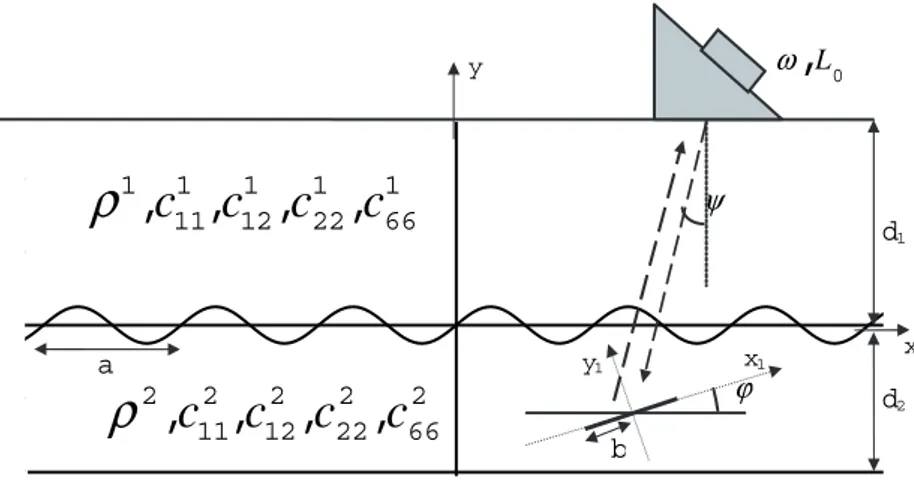
The two-dimensional scattering geometry is shown in Fig. 1. The cladding is the lower material which is bounded above with the corrugated interface to the base material. The probe is performing a line scan on the surface of the base material. The interface is assu-med to be sinusoidally corrugated as shown. The choice of a sinusoidal corrugation is made for two reasons. Firstly, this corrugation is a reasonable model of a real welded cladding interface (Hudgell, 1994). It is also a convenient mathematical formulation of the interface that is relatively easy to handle, one important reason being that it is a periodic function. The location of the crack is also shown in Fig. 1. The height of the crack is 2b and the depth from the interface is yc. But also the horizontal position xc of
the crack is important because it describes where the crack is located relative the peaks and valleys of the corrugations (alternatively one could choose to fix the crack at x=0 and move the interface sideways).
Both the cladding and the base material can be anisotropic and this is described by the stiffness constants Cij (in abbreviated notation) with an additional upper index when it is
necessary to distinguish between the two materials. To have a two-dimensional problem the xy-plane must be a plane of elastic symmetry. Then a decoupling into two two-dimensional problems is possible: one is the simpler SH problem where the only displacement component is out of the plane and the other is the coupled P-SV problem where there are only components in the plane. Both these cases are considered separa-tely in the following, because there are important differences in the ways they have been treated. y 1 66 1 22 1 12 1 11 1
,
,
,
,
c
c
c
c
ρ
2 66 2 22 2 12 2 11 2,
,
,
,
c
c
c
c
ρ
x1 x ψ ϕ b d1 0,
L ω y1 d2 a10
2.1 SH waves
For the SH waves the scattering problem is a scalar one for the out-of-plane component of the displacement. For this case the corrugations are treated in an approximate way by making a series expansion which leads to boundary conditions on the flat middle surface. The complicating fact with this boundary condition is that it contains coeffi-cients that are periodic functions along the interface.
To solve the scattering problem the Green’s function for the structure without the crack is first determined. (A Green’s function for a problem is a solution for the correspon-ding problem with a point source.) This is essentially the same type of problem that was solved in the previous project and it can be done by Fourier transform techniques, where the periodic coefficients of the boundary condition are the only complicating factor, leading in effect to an infinite system of equations.
Once the Green’s function is determined the crack scattering can be reduced to a hypersingular integral equation for the crack-opening-displacement (COD) over the surface of the crack. The Green’s function enters into this integral equation and is responsible for that all surface terms vanish except the one over the crack. To discretize the integral equation the COD is expanded in Chebyshev functions which have the virtue of having the correct square root behaviour at the crack edges. For the conver-gence and stability of the numerical scheme this correct edge behaviour is absolutely essential. Projecting the integral equation onto the Chebyshev functions the discretized version of the equation is obtained as a linear system of equations. The coefficients in this system are integrals over infinite ranges that need some care in the evaluation. Ultrasonic probes have been modelled in previous projects. This is followed here, although the simplest version is chosen. Should reasons appear, it is easy to change to other probe models. As chosen, the model prescribes the shear stress on the contact area of the probe. This stress is constant except for a phase that accounts for the angle of the probe (this phase in the frequency domain corresponds to a time lag in the time domain). In this two-dimensional SH case the probe is characterized by its position, size, frequency, and bandwidth. However, all computations reported later are with a fixed frequency, particularly because this gives fast computations. For a line scan this is also adequate and according to experience this gives enough accuracy in most cases. However, if A scans are to be computed and if travel time data are needed, it is of course necessary to make computations in the time domain. At the cost of increased computational times, roughly by a factor 100 (the number of frequencies needed), this is straightforward to do.
To model a receiving probe a reciprocity argument is used. This essentially gives that it is enough to know the characteristics of the probe as transmitter to also know its characteristics as receiver. In the formulation it is in fact only the probe field distribution over the defect, the crack in this case, that is needed.
2.2 P-SV waves
The coupled P-SV waves have vector character and are therefore somewhat more complicated to treat. In addition, the approximation with periodic boundary conditions on a flat interface is lifted. Instead the boundary conditions are applied exactly at the corrugated interface. As for the SH case the crack scattering is formulated as a hyper-singular integral equation that is solved in the same way with expansions in and project-tions on the Chebshev funcproject-tions (again accounting for the correct edge condiproject-tions). The Green’s function (a tensor in this case) enters the integral equation in the same way as before. But the calculation of the Green’s tensor is now quite complicated, both because of the vector and tensor character of the problem, and because of the truly corrugated interface. In the previous project (Krasnova et al., 2005), however, the corrugated inter-face was treated with the null field approach, and essentially the same procedure can be followed here, leading to quite complicated expressions. The numerical compu-tations again contain complications with integrals over infinite ranges.
The probe modelling in both transmission and reception is again performed in the usual way. For the coupled P-SV waves it is the pressure from the probe that is prescribed on the surface.
12
Numerical results
In this section some numerical examples showing line scans are given to illustrate the effects of the cladding on the crack scattering response. There are many parameters to vary, but only some of those that are believed to be of most interest have actually been varied. Results for the SH and P-SV problems are given separately, but first the geometry and material parameters that are common for the two cases are given.
The geometry is given in Fig. 1. The upper base material is chosen as an isotropic steel and the lower cladding is an anisotropic austenitic steel (weld material). The thickness of the base material is 30 mm and the thickness of the cladding is 5 mm. The base material is an isotropic ferritic steel with pressure wave speed 5.74 mm/s and shear wave speed 3.13 mm/s and density 8420 kg/m3. The cladding is a weld material with density 8120 kg/m3 that is transversely isotropic with stiffnesses C22 = 216.0, C11 = C33 =
262.7, C55 = 82.2, C44 = C66 = 129.0, C12 = C23 = 145.0, and C13 = 98.2, all measured in
GPa. The stiffnesses are given in the crystal system and to fully specify the material also the orientation of the crystal system must be given. In these two-dimensional problems it is enough with one angle giving the preferred direction, which is the 2 direction (y direction) in the crystal system. This direction is fixed to the y direction, as this approximately corresponds to the direction in a real welded cladding.
The interface between the cladding and the base material is sinusoidally corrugated with a period of 5 mm. The peak-to-peak height of the corrugations is 0, 1, or 2 mm, and as will be seen this parameter has important effects on the signal response.
The crack is situated in the cladding. The centre of the crack is located at the horizontal distance xc and the vertical distance yc from the origin that is situated at the interface,
see Fig. 1. Note that the interface is a sinus function, so it is zero and has positive slope at x = 0. The importance of the parameter xc is thus to measure the location of the crack
relative the hills and valleys of the corrugations.
Only a single probe in pulse-echo is used which performs a line scan on the base material. The width of the probe is 10 mm and it is operating at the fixed frequency 1 MHz. As a shear (SH or SV) probe this means that the near field length of the probe is about 8 mm. The angle of the probe is 0 or 45 degrees.
3.1 SH waves
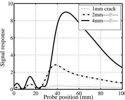
For the SH waves the fixed probe angle 45 degrees is used in all the examples. First the influence of the crack size is studied. Figure 2 gives the signal response for a flat interface and vertical surface-breaking cracks of height 1, 2, and 4 mm. As mentioned this means that the crack mouth remains closed. Note that the crack size is of the same order as the wavelength or smaller and therefore the smaller cracks scatter much less than the larger and there is no simple way to say how the signal response depends on frequency.
0 20 40 60 80 100 0 2 4 6 8 10 Probe position (mm) Signal response 1mm crack 2mm−−//−− 4mm−−//−−
Figure 2: Signal response from a vertical surface-breaking crack of different heights and a flat interface.
Figure 3 shows the signal response in the same situation as in Fig. 2 with the exception that the interface is corrugated with a peak-to-peak value of 1 mm. Generally the signal response drops a little with almost 2 dB. However, it may instead happen that the response increases with the introduction of the corrugation. The results also become more “wiggly” with curves that have small ripples on top of the overall trends.
0 20 40 60 80 100 0 2 4 6 8 10 Probe position (mm) Signal response 1mm crack 2mm −−//−− 4mm −−//−−
Figure 3: Signal response from a vertical surface-breaking crack of different heights and a corrugated interface.
0 20 40 60 80 100 0 5 10 15 20 25 Probe position (mm) Signal response
−20 deg. from vertical vertical
+20 deg. from vertical
Figure 4: Signal response from a 4 mm surface-breaking crack of varying tilt and a corrugated interface.
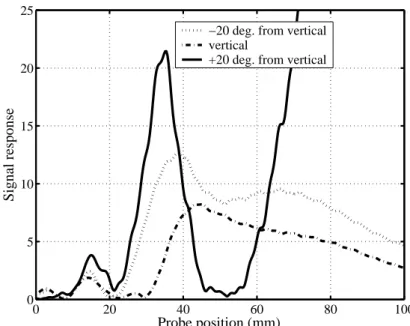
Figure 4 shows the effects of varying the tilt from the vertical for a surface-breaking 4 mm crack. It is not surprising that there are great changes between the cases. Note that the rotation +20 degrees gives a crack that is hit normally by the ultrasound for a probe position around 100 mm and therefore a large response is obtained.
Figure 5 shows the effects of translating a 4 mm surface-breaking crack in the horizontal direction so that it shifts positions relative the hills and valleys of the corrugations. There is a difference of almost 5 dB between the largest and smallest peaks. 0 20 40 60 80 100 0 5 10 15 Probe position (mm) Signal response xc=0mm xc=2mm xc=4mm
Figure 5: Signal response from a 4 mm vertical surface-breaking crack with varying horizontal translation and a corrugated interface.
2.3 P-SV waves
For the coupled P-SV waves an unangled probe of P type is first considered. It must then be noted that the signal response as calculated here is only the extra part due to the crack. For an unangled probe there are of course additional parts from the interface and the back surface (and multiple reflections between these as later arrivals). But the part from the crack may be possible to get from a gating in time. Anyway, the results below tell what the influence of the corrugations is on the crack scattering.
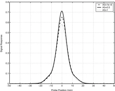
Figure 6 shows the signal response for a 4 mm horizontal crack at yc = 3 mm (and xc = 0
mm) with varying corrugation height. Note that the corrugation height given in the figure is the half-height, so that the peak-to-peak height is 0, 1, or 2 mm. This means that the highest corrugation height here is twice that for the SH waves in the previous subsection. As opposed to the development for SH waves, where an approximation was used so that the corrugations must be small, here the corrugation height can be arbitrary, and as noted in the introduction a height of 2 mm and a period of 5 mm is quite typical of real welded claddings. The curves are normalized by the response from a crack of the same size at the same position without a cladding (i.e. assuming the base material throughout). The influence of the cladding is of the order of 1 dB. The corrugated interface also gives a slight asymmetry of the curves as seen by a careful examination. Figure 7 shows the signal response when the crack is translated. This means that the crack is situated at different positions relative the peaks and valleys of the interface. This naturally gives a translation of the peak response, but it also gives a change of the peak response. Between the three translations shown the difference is as large as about 2 dB. −500 −40 −30 −20 −10 0 10 20 30 40 50 0.1 0.2 0.3 0.4 0.5 0.6 0.7 0.8 Probe Position (mm) Signal Response A0=1e−6 A0=0.5 A0=1
Figure 6: Signal response from a 4 mm horizontal crack and varying corrugation height; unangled P probe.
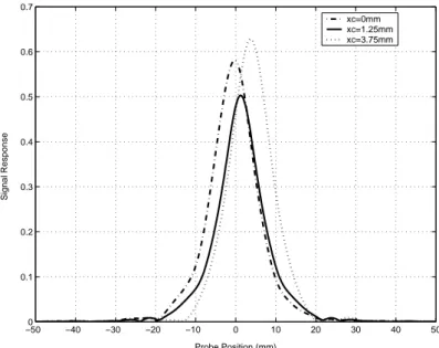
−500 −40 −30 −20 −10 0 10 20 30 40 50 0.1 0.2 0.3 0.4 0.5 0.6 0.7 Probe Position (mm) Signal Response xc=0mm xc=1.25mm xc=3.75mm
Figure 7: Signal response from a 4 mm horizontal crack and varying translation relative the corrugations; unangled P probe.
Figure 8 shows the signal response when the crack is tilted 45, 70, or 90 degrees from the horizontal and the interface is corrugated with peak-to-peak height 2 mm. The response is decreasing with increasing tilt as expected. There is also a tendency for the response to become more unsymmetrical with increasing tilt. It should be noted that the crack height is 4 mm and the P wavelength is about 6 mm so that the crack scatters like one unit and it is not possible to distinguish the crack tip echoes. Another way to put this is to say that the two crack tip echoes are so close as to more or less completely overlap. −500 −40 −30 −20 −10 0 10 20 30 40 50 0.1 0.2 0.3 0.4 0.5 0.6 0.7 Probe Position (mm) Signal Response phi=45 phi=70 phi=90
Figure 8: The signal response from a 4 mm crack with varying tilt below a corrugated interface; unangled P probe (tilt is measured relative the horizontal).
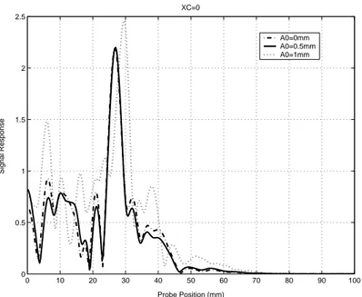
0 10 20 30 40 50 60 70 80 90 100 0 0.5 1 1.5 2 2.5 XC=0 Probe Position (mm) Signal Response A0=0mm A0=0.5mm A0=1mm
Figure 9: Signal response from a 4 mm vertical crack and varying corrugation height; 45 degree SV probe.
Turning now to a 45 degree SV probe, Figure 9 shows the response from a vertical crack for varying corrugation height. The maximum is expected to appear a little above 30 mm, whereas in the figure it appears a little below 30 mm. However, it should be noted that the angle of the probe is here specified by its phase shift and this gives the specified angle for an infinite probe. Here the probe is rather small in terms of wavelengths and then the “true” angle can deviate from the nominal.
Figure 10 shows the effect of translating the vertical crack relative the corrugation for the 45 degree SV probe. As for the unangled P probe the effects of the corrugations are large; the biggest difference between the peaks is 3.5 dB in the figure (but even bigger
0 10 20 30 40 50 60 70 80 90 100 0 0.5 1 1.5 2 2.5 3 3.5 Probe Position (mm) Signal Response xc=1.25mm xc=2.5mm xc=3.75mm
Figure 10: Signal response from a 4 mm vertical crack and varying horizontal translation; 45 degree SV probe.
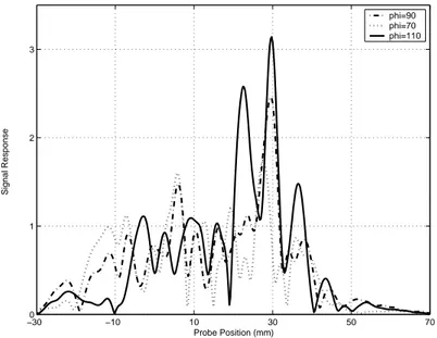
−300 −10 10 30 50 70 1 2 3 Probe Position (mm) Signal Response phi=90 phi=70 phi=110
Figure 11: Signal response from a 4 mm crack with varying tilt below a corrugated interface; 45 degree SV probe (tilt is measured relative the horizontal).
differences can of course appear between other translations, a systematic search for this has not been performed).
Finally, Fig. 11 shows the effects of tilting the 4 mm crack 20 degrees either way from the vertical. The tilt that is labelled as 110 degrees gives a crack that is hit more closely to the normal so it is natural that it gives the strongest response.
4 Conclusions
The present report describes work that has been done to model the scattering by cracks in a cladding. The developments are restricted to two dimensions but both the simpler SH problem and the more complicated in-plane P-SV problem are treated. The cladding (and also the base material) can be anisotropic and the interface between the base material and the cladding can be corrugated. To solve the scattering problems a hypersingular integral equation technique is employed. The Green’s function that plays a central role in this formulation and takes care of the whole structure except for the crack has been calculated in different ways. In the SH part the corrugated interface is approximated to a planar one and a straightforward Fourier integral representation of the Green’s function can be given. In the P-SV part the corrugated interface is treated exactly by the null field approach. Transmitting and receiving ultrasonic probes are treated in the standard way.
The main conclusion that can be drawn from the project is that the corrugated interface has important and often large effects on the signal response. This has been illustrated in a few cases, but no systematic parametric studies have been performed. As an example the signal response from a specific crack is very dependent on where it is situated relative the hills and valleys of the corrugations; the response can be doubled by just shifting the crack a few millimetres sideways.
As a continuation of the project work has started to look at corresponding three-dimensional situations with strip-like and rectangular cracks.
20
References
Boström, A., Propagation of ultrasound in claddings, SKI Report 2004:19, Swedish Nuclear Power Inspectorate, Stockholm 2004.
Halkjaer, S., Elastic wave propagation in anisotropic, inhomogeneous materials –
application to ultrasonic NDT, Thesis, Department of mathematical modelling,
Technical University of Denmark, Lyngby, Denmark 2000.
Hannemann, R., Modeling and imaging of elastodynamic wave fields in inhomogeneous
anisotropic media – an object-oriented approach, Thesis, Department of electrical
engineering, University of Kassel, Kassel, Germany 2001.
Hudgell, R.J., Handbook on the ultrasonic examination of austenitic clad components, The International Institute of Welding and Joint Research Centre, European Commission, Luxembourg 1994.
Krasnova, T., Jansson, P.-Å., and Boström, A., Ultrasonic wave propagation in an anisotropic cladding with a wavy interface, Wave Motion 41, 163-177, 2005.
Zagbai, T., and Boström, A., 2D SH wave scattering by a crack in a cladding, Report, Department of Applied Mechanics, Chalmers University of Technology, Göteborg 2005.
Zagbai, T., and Boström, A., 2D SH wave scattering by a crack in a cladding, Rev.
Progress Quant. Nondestr. Eval. Vol. 25, pp. 81-88, eds Thompson, D.O., and
Chimenti, D.E., Am. Inst. Phys., Melville, N.Y. 2006.
Zagbai, T., Jansson, P.-Å., and Boström, A., 2D P-SV scattering by a crack in a cladding, Report, Department of Applied Mechanics, Chalmers University of Technology, Göteborg, 2006.