Real-Time Component Integration using
Runnable Virtual Nodes*
Rafia Inam, Jukka M¨aki-Turja, Mikael Sj¨odin, Jiˇr´ı Kunˇcar
M¨alardalen Real-Time Research Centre, V¨aster˚as, SwedenEmail: {rafia.inam, jukka.maki-turja, mikael.sjodin}@mdh.se, jiri.kuncar@gmail.com
Abstract—We present the concept of runnable virtual nodes (RVNs) as means to achieve predictable integration and tem-poral error-containment of real-time software components. An RVN exploits the latest techniques for hierarchical scheduling and is intended as a coarse-grained component for single-node deployment, that provides functional and temporal isolations with respect to its environment. It uses a two-level deployment process; i.e. deploying functional entities to RVNs and then deploying RVNs to physical nodes. The two-level deployment process not only gives development benefits with respect to composability, system integration, testing, validation and certification but also leverages the hierarchical scheduling to preserve the validity of an RVN’s internal temporal behaviour when integrated with other components. We have applied our approach to a simple case study, implemented in the ProCom component-technology executing on top of FreeRTOS-based hierarchical scheduling and present our initial results as a proof-of-concept.
Index Terms—real-time software components; component in-tegration; hierarchical scheduling
I. INTRODUCTION
In this paper we target development of the large class of embedded systems which is required to perform multiple simultaneous control-functions, potentially having real-time requirements. From the development point of view, it often makes sense to develop different control-functions as separate software-components [1]. Typically, these components are first developed and tested in isolation, and later integrated to form the final software for the system. Furthermore, many industrial systems are developed in an evolutionary fashion, reusing components from previous versions or from related products. It means that the reused components are re-integrated into new environments.
We address the challenges of preserving real-time properties within the components, in order to make the integration of real-time components predictable. To solve this problem, we pro-pose the concept of a runnable virtual node (RVN), which is an execution-platform concept that preserves temporal properties of the software executed within it. It introduces an intermediate level between the functional entities and the physical nodes. Thereby, it leads to a two-level deployment process instead of a single big-stepped deployment; i.e. deploying functional entities to the virtual nodes and then deploying virtual nodes to the physical nodes.
We introduce the RVN, which includes the executable representation of components, a real-time scheduler to be
* This work is supported by the Swedish Foundation for Strategic Research (SSF), via the research programme PROGRESS.
executed within a server in the HSF, and a resource allocation for the server. The server executes with a guaranteed temporal behavior, using its allocated CPU bandwidth, regardless of any other execution on the physical node. Thus, once a server has been configured for the RVN, its non-functional (timing) properties will be preserved along with its functional properties when the RVN is integrated with other RVNs on a physical node.
The main contributions of this paper are:
• We realize the concept of runnable virtual nodes for
the ProCom component technology [2] by exploiting the HSF implementation [3], [4] for the FreeRTOS real-time operating system [5].
• We introduce a two-level deployment process; i.e. deploy-ing functional entities to RVNs in a first step (durdeploy-ing which, e.g., the timing properties of RVNs are validated), and then, deploying RVNs to the physical nodes in a second step (integrating RVNs along with their preserved timing properties). The two-level process gives devel-opment benefits with respect to composability, system integration, testing, validation, certification.
• We demonstrate the runnable virtual node’s properties with respect to temporal isolations, and fault-containment through a case study.
Outline: Section II gives an overview about the ProCom component model and the HSF implementation. In Section III, we describe the RVN and in Section IV, we discuss how the two-level deployment helps in preserving the real-time properties within RVN. Section V presents a case-study and the results. Finally, Section VI concludes the article.
II. BACKGROUND
This section presents the background technologies on which our work is based on.
A. The ProCom Component Model
Component-Based Software Engineering (CBSE) and Model-Based Engineering (MBE) are two emerging ap-proaches to develop embedded control systems like software used in trains, airplanes, cars, industrial robots, etc. The Pro-Com component technology combines both CBSE and MBE techniques for the development of systems and subsystems, hence also exploits the advantages of both [2].
The ProCom component model can be described in two distinct realms: the modeling and the executable realms as
Fig. 1. An overview of the modeling formalisms and synthesis artefacts.
shown in Figure 1. In the Modeling realm, the models are made using CBSE and MBE while in the executable realm, the synthesis of runnable entities is done from the model entities. 1) The Modeling Realm: Modeling in ProCom is done by four discrete but related formalisms (see Figure 1). The first two formalisms relate to the system functionality modeling while the later two represent the deployment modeling of the system. Modeling in ProCom is done by four discrete but related formalisms as obvious from Figure 1. Functionality of the system is modeled by the ProSave and ProSys components at different levels of granularity. The basic functionality (data and control) of a simple component is captured in the ProSave component level (passive in nature). At the second formalism level, many ProSave components are mapped to make a complete subsystem called ProSys (active in nature) [2]. Many ProSys components can be mapped together on a virtual node (many-to-one mapping) together with a resource budget required by those components. After that, many virtual nodes could be mapped on a physical node. The relationship is again many-to-one. This part represents all the physical nodes and their inter-communication [6].
2) The Executable (or Runnable) Realm: The primitive ProSave components are represented as a simple C language source code in runnable form. From this C code, the ProSys runnables are generated which contain a collection of oper-ating system tasks. RVNs implement the local scheduler and contain the tasks in a server. Final binaries are generated by connecting different RVNs together with a global scheduler and using a middleware API to provide communications among RVNs.
B. Hierarchical Scheduling Framework and its Implementa-tion in FreeRTOS
A two-level Hierarchical Scheduling Framework (HSF) is used to provide temporal isolation among a set of subsys-tems [7]. In the hierarchical scheduling, the CPU time is partitioned among many subsystems (or servers), that are scheduled by a global (system-level) scheduler. Each server contains its own internal set of tasks that are scheduled by a local (subsystem-level) scheduler as shown in Figure 2.
The HSF gives the potential to develop and analyze subsys-tems in isolation from each other. As each subsystem has its own local scheduler, after satisfying the temporal constraints, the temporal properties are saved within each subsystem. Later, a global scheduler is used to schedule all the subsystems
Hierarchical Scheduling Framework
Global FPS Scheduler
. . .
Global Shared Resources
SubSystem n
Local FPS Scheduler
Task1 . . . Taskn Local Shared Resources S R P S R P SubSystem 1 Local FPS Scheduler Task1 . . . Taskn Local Shared Resources S R P S R P H S R P H S R P
Fig. 2. Two-level Hierarchical Scheduling Framework.
together without violating the temporal constraints that are already analyzed and stored in the subsystems. Accordingly, we can say that the HSF provides partitioning of the CPU between different servers. Thus, server-functionality can be isolated from each other for, e.g., fault containment, composi-tional verification, validation and certification, and unit testing. Our RVN implementation is based on a two-level HSF for the FreeRTOS operating system [3]. FreeRTOS is a portable open source real-time kernel which is small and scalable, supports 23 different hardware architectures, and is easy to extend and maintain [5].
The official release of FreeRTOS only supports a single level fixed-priority scheduling. We have, however, previously presented an implementation of two-level HSF for FreeR-TOS [3] with associated primitives for hard real-time sharing of resources both within and between servers [4]. The HSF implementation supports two kinds of servers, idling peri-odic [8] and deferrable servers [9]. The implementation uses fixed-priority preemptive scheduling (FPPS) for both global and local-level scheduling. For local resource-sharing (within a server) the Stack Resource Policy (SRP) [10] is used, and for global resource-sharing (between servers) the Hierarchical Stack Resource Policy (HSRP) has been implemented [4].
III. RUNNABLEVIRTUALNODE
Here we present the details of the RVN and its implemen-tation in the ProCom component technology.
A. The RVN in ProCom
In ProCom, a virtual node is an integrated model concept. It means that the virtual nodes exist both on the modeling and on the executable levels as shown in Figure 1. At the modeling level, a virtual node is a container for a set of integrated ProSys-components plus the execution resources (a period and budget) required for these ProSys-components. The input and output ports of those components are inherited by the virtual node. The priorities of virtual nodes cannot be assigned at the modeling level. The priorities of a component
are relative to other components in the system (we use fixed-priority preemptive scheduling); hence components fixed-priority assignment is done during the final step of integrating virtual nodes to physical nodes. In the executable realm, they are called runnable virtual nodes.
B. The RVN Implementation
The RVN is intended for coarse-grained components for single node deployment and with potential internal multitask-ing. An RVN is implemented as a server within an HFS, and includes the set of tasks, a resource allocation, and a real-time scheduler. The task set comes from ProSys runnables which are mapped to an RVN. The scheduler is local-level, and schedules the task set according to allocated resources using a scheduling policy (which in the current implementation is assumed to be FPPS). The final executables that can be downloaded and executed on the physical node consists of a set of RVNs and a top-level real-time scheduler linked together. The top-level scheduler in the HSF is responsible for dispatching the RVN-servers according to their bandwidth reservations.
As long as the allocated budgets to RVN-servers (at the modeling level) are provided, the timing properties are guar-anteed at the execution. Thus, with the use of servers in HSF, the timing properties of RVNs are preserved during integration and reuse. Further, it reduces the efforts related to testing, validation and certification.
IV. THETWO-LEVELDEPLOYMENTPROCESS
The two-level deployment process is made possible by the RVN concept; means that we are maintaining the modeling hierarchy (see Figure 1) also at run-time by executing the tasks of each virtual node within a server, instead of flattening the whole system to a single level of tasks. The system is generated in two steps rather than a single big deployment. A. The First Step of Deployment
In the modeling realm, a virtual node consists of a set of ProSys-components with an added resource reservation hQ, P i. This resource reservation makes it possible to start reasoning about the timing properties of different components inside the virtual node (i.e. inside the top-level ProSys-components). In the executable realm, the RVN is constructed by mapping the set of tasks that have been synthesized from the integrated ProSys-components to a server and assigning scheduling parameters (which in the current implementation means assignment of task-priorities). Internal validity of the timing-constraints of the RVN can then be assessed using, e.g., simulation, testing or a local scheduling-analysis provided in [4]. In this manner, after configuration the server preserves its timing properties with it.
B. The Second Step of Deployment
In the modeling realm, a set of virtual nodes is mapped to model a physical system. This means that one or more virtual nodes are allocated to each hardware node in the system. In
the executable realm, we create the final binary for a hardware node by mapping a set of RVNs to that node along with a top-level scheduler in HSF, resolving local-RVN communications (communication among RVNs mapped on the same hard-ware node), and mapping distributed-RVN communications (communication among RVNs mapped on different hardware nodes) with remote RVNs to the communications media. At this point it is also necessary to assign scheduling parameters in terms of server-priorities. To access that a feasible priority assignment has been made, a global scheduling-analysis [4] is performed.
V. CASESTUDY
The PRIDE tool [11] supports development of systems using ProCom component models and we have used it for developing an example of cruise controller (CC) for automotive applica-tions. Our motivating case study is simple, but exercises the execution-time properties and evaluates the integration and the timing fault-containment of the run-time components. The CC system is realized and exercised to test the temporal isolations among run-time components. Its basic functionality is to keep the vehicle at a constant speed.
A. System design
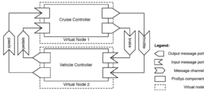
The CC system is designed using two ProSys components, Cruise Controller (CC) and Vehicle Controller (VC), which are modeled and deployed on two different virtual nodes (see Figure 3). Virtual nodes communicate with each other through the middleware using input and output message ports.
Fig. 3. Deploying ProSys components on virtual nodes.
The detailed design of the ProSys components is shown in Figures 4(a), and 4(b). These ProSys components are mapped to the virtual nodes. The CC ProSys component is mapped to the Virtual Node1 and the VC ProSys component is mapped to the Virtual Node2 as clear from Figure 3. Each virtual node is assigned an execution budget and a period hQ, P i to be executed in a local server within a two-level HSF at the modeling level in the PRIDE tool.
B. Synthesis
The PRIDE tool automatically synthesizes the code from the ProCom models at different stages. It takes the models as input, and generates all low-level platform independent code. To generate the ProSys runnables, a task set is generated for each ProSys component. One task is synthesized for each clock and given in Table II. For CC example, two tasks are
Control Unit HMI Input HMI Output Clock Clock brake current speed mode desired speed current speed current speed mode desired speed current speed throttle brake brake
(a) The Cruise Controller (CC) component
brake current speed brake Clock throttle Clock Throttle pedal Brake pedal Speedometer Engine controller Brake controller Clock Calc Max Value Calc Max Value external input external input
(b) The Vehicle Controller (VC) component Fig. 4. The detailed design of ProSys components.
generated for the CC ProSys component: CCT1 task including HMI Input and Control Unit; and CCT2 task including HMI Output component. Three tasks are generated for the VC ProSys component: VCT1 task including Throttle pedal, Calc Max Value, and Engine Controller; VCT2 task including Brake pedal, Calc Max Value, and Brake Controller; and VCT3 task including the Speedometer.
In the first step of the final synthesis/deployment process for the case study, two RVNs are produced for CC system: one RVN for Virtual Node1 and one for Virtual Node2. These generated nodes contain tasks definitions in them. In the second step of the final synthesis/deployment part, the priorities are assigned to the RVNs (also called servers now) and to the tasks in them. Four servers are generated for the example.
A System server is generated to provide communication among the RVNs. It has the highest priority of all the other servers, i.e. 7 (there are 8 different server priorities: from lowest priority 0 to the highest 7). The System server contains two tasks: a Sender and a Receiver task; whose functionality is to send and receive the data shared among RVNs respectively. An Idle server is generated in the system with the lowest priority of all the other servers, i.e. 0, contain-ing an idle task in it. All the other servers in the system have the priority higher than 0.
The CC system contains two more servers in addition to System and Idle server: a CC server and a VC server associated with Virtual Node1 and Virtual Node2 respectively. The priorities, periods and budgets for these servers are given in Table I.
We present results with the idling periodic server. An idle taskper server is generated that has the lowest priority. It runs
Server CC VC SYSTEM
Priority 2 1 7
Period 40 60 20
Budget 10 15 4
TABLE I
SERVERS USED TO TEST THECCANDACCSYSTEMS BEHAVIORS.
when its server has the budget remaining but none of its task is ready to execute. Task properties and their assignments to the servers are given in Table II.
C. Evaluation and Discussion
We have performed the experimental evaluation of the case study on an AVR-based EVK1100 board [12]. The 32-bit AVR32UC3A0512 micro-controller runs at the frequency of 12MHz and its tick interrupt handler at 1ms(milli seconds). The FreeRTOS operating system with its HSF implementation is used on the micro-controller using FPPS scheduling policy at both levels for idling periodic servers. Its tick-handler runs at the rate of 1ms. The experimental results are presented in the form of visualization of servers executions in Figures 5(a), and 5(b).
In these Figures, the horizontal axis represents the execution time starting from 0. In the task’s visualization, the arrow rep-resents task arrival and a gray rectangle means task execution. In the server’s visualization, the numbers along the vertical axis are the server’s capacity, the diagonal line represents the server execution while the horizontal line represents either the waiting time for the next activation (when budget has depleted) or the waiting for its turn to execute (when some other server is executing). Since these are idling periodic servers, all the servers in the system execute until their budget depleted, if no task is ready then the idle task of that server executes.
1) Testing Temporal Isolation and Predictable Integration: Figure 5(a) demonstrates the system execution under the nor-mal load situation. The system’s behavior is also tested during the overload situation to test the temporal isolation among the RVNs. For example, if one server (RVN) is overloaded and its tasks miss deadlines, it should not affect the behavior of other servers (RVN) in the system.
The same example is executed to perform this test but with the increased utilization of the CC server as shown in Figure 5(b). The execution times of tasks CCT1 and CCT2 are increased by adding busy loops, hence making the CC server’s utilization greater than 1. Therefore the low priority task CCT2 misses its deadlines at time 54. CCT2 is preempted at time 14 because of the CC server’s budget expiration, and starts it’s execution again when next time the server is replenished. Further, the CC is never idling because it is overloaded (the Idle task of CC server is not executed in Figure 5(b)).
The overload in the CC server does not effect the behavior of any other server in the system as obvious by comparing Figure 5(b) with Figure 5(a). The VC server has a lower priority than the CC, but still it receives its allocated resources and its tasks meet their deadlines. It shows a predictable timing behaviour of RVNs that further eases their integration. It also manifests that the temporal errors are contained within the
Tasks CCT1 CCT2 VCT1 VCT2 VCT3 Sender Receiver
Server CC CC V C V C V C System System
Priority 2 1 1 1 2 2 2
Period 40 60 60 60 40 20 20
TABLE II
TASKS IN THE THREE SERVERS.
(a) The CC system during normal load
(b) The CC system during overload situation Fig. 5. The trace for servers in the CC and ACC systems.
faulty RVN only and their effects are not propagated to other RVNs in the system as clear from the Figure 5(b).
VI. CONCLUSIONS
We present the concept of runnable virtual nodes (RVNs) as a means to achieve predictable integration and timing fault-containment of real-time components to facilitate the development of complex real-time systems. We use a two-level deployment process that leverages the hierarchical scheduling framework (HSF) to preserve timing behavior of RVNs.
We have presented a proof-of-concept case study and our results demonstrate the temporal error containment within an RVN without altering their temporal behaviour. Our work is based on the ProCom component-technology using the HSF implementation for FreeRTOS and is executed on an AVR-based EVK1100 board. However, our concept has been de-signed to be applicable to commercial component technologies like AADL, AUTOSAR [13].
For future work, we plan to make the RVN an executable reusable entity.
REFERENCES
[1] I. Crnkovic and M. Larsson, editors. Building Reliable Component-Based Software Systems. Artech House publisher, 2002. ISBN 1-58053-327-2.
[2] S´everine Sentilles, Aneta Vulgarakis, Tom´aˇs Bureˇs, Jan Carlson, and Ivica Crnkovi´c. A Component Model for Control-Intensive Distributed Embedded Systems. In 11th International Symposium on Component Based Software Engineering, pages 310–317, October 2008.
[3] Rafia Inam, Jukka M¨aki-Turja, Mikael Sj¨odin, S. M. H. Ashjaei, and Sara Afshar. Support for Hierarchical Scheduling in FreeRTOS. In IEEE International Conference on Emerging Technologies and Factory Automation (ETFA’ 11).
[4] Rafia Inam, Jukka M¨aki-Turja, Mikael Sj¨odin, and Moris Behnam. Hard Real-time Support for Hierarchical Scheduling in FreeRTOS. In 7th Annual Workshop on Operating Systems Platforms for Embedded Real-Time Applications (OSPERT’ 11), pages 51–60, Porto, Portugal, 2011. [5] FreeRTOS web-site. http://www.freertos.org/.
[6] Jan Carlson, Juraj Feljan, Jukka M¨aki-Turja, and Mikael Sj¨odin. Deploy-ment Modelling and Synthesis in a Component Model for Distributed Embedded Systems. In Proceedings of the 36th Euromicro Confer-ence on Software Engineering and Advanced Applications (SEAA’ 10), September 2010.
[7] Z. Deng and J.W.-S. Liu. Scheduling real-time applications in an open environment. In IEEE Real-Time Systems Symposium(RTSS’97), pages 308–319, 1997.
[8] L. Sha, J.P. Lehoczky, and R. Rajkumar. Solutions for some Practical problems in Prioritised Preemptive Scheduling. In Proc. IEEE Real-Time Systems Symposium (RTSS), pages 181–191, 1986.
[9] J.K. Strosnider, J.P. Lehoczky, and L. Sha. The deferrable server algorithm for Enhanced Aperiodic Responsiveness in Hard Real-time Environments. IEEE Transactions on Computers, 44(1), 1995. [10] T. Baker. Stack-based scheduling of real-time processes. Journal of
Real-Time Systems, 3(1):67–99, 1991.
[11] PRIDE Team. PRIDE: the PROGRESS Integrated Development Envi-ronment, 2010. ”http://www.idt.mdh.se/pride/?id=documentation”. [12] ATMEL EVK1100 product page. http://www.atmel.com/dyn/Products/tools
card.asp?tool id=4114.
[13] R. Inam, J. M¨aki-Turja, J. Carlson, and M. Sj¨odin. Virtual Node – To Achieve Temporal Isolation and Predictable Integration of Real-Time Components. International Journal on Computing (JoC), 1(4), 2012.