Efficient hydraulic pumps, motors and
transformers for hydraulic hybrid
systems in mobile machinery
Peter A J Achten, Georges E M Vael and Kim Heybroek
Conference article
Cite this conference article as:
A, P., E, G., Heybroek, K. Efficient hydraulic pumps, motors and transformers for
hydraulic hybrid systems in mobile machinery, In VDI-Fachkonferenz Getriebe in
Mobilen Arbeitsmaschinen, VDI-Wissensforum; 2011, pp. 1-19. ISBN:
9783942980036
Copyright: VDI-Wissensforum
The self-archived postprint version of this conference article is available at Linköping
University Institutional Repository (DiVA):
http://urn.kb.se/resolve?urn=urn:nbn:se:liu:diva-132925
Efficient hydraulic pumps, motors and transformers for hydraulic hybrid systems in mobile machinery 1
Efficient hydraulic pumps, motors and transformers
for hydraulic hybrid systems in mobile machinery
Peter Achten, Georges Vael
Innas BV, Breda, Netherlands
Kim Heybroek
Volvo Construction Equipment, Eskilstuna, Sweden
Summary
A detailed simulation of a large 33 metric ton wheel loader, carrying out the short loading cycle, has been performed. Two systems have been compared and examined side by side:
• The conventional system, having a mechanical transmission for driving the wheels and a conventional load sensing hydraulic circuit for the work and steering cylinders.
• A new hydraulic hybrid system for the wheel drive and the implements, applying new and efficient hydrau-lic pumps and motors. The core of the new system is the hydrauhydrau-lic transformers which convert and control all the hydraulic power flows inside the loader.
The new system results in a reduction of the fuel consumption of about 50% in the analyzed cycle. The new transmission and hydraulic system also results in a strong reduction of the cooler demands.
Zusammenfassung
Es wurde eine detaillierte Analyse eines großen, 33 Tonnen Radladers auf einem Y-Zyklus vorgenommen. Zwei Systeme wurden verglichen:
• Das herkömmliche System, mit mechanischem Antriebsstrang für den Radantrieb und ein konventionelles Load-Sensing System für die Arbeitsfunktionen und für die Lenkung.
• Ein neuer hydraulischen Hybridantrieb der Räder und der Arbeitsfunktionen, in dem neue und effiziente hydraulische Pumpen und Motoren angewendet werden. Die Schlüsselkomponente dieses neuen Hyb-ridsystems sind die hydraulische Transformatoren, die alle hydraulische Leistungsströme in dem Rad-lader transformieren und regeln.
Das neue System realisiert, in den analysierten Zyklus, eine Verbrauchssenkung von etwa 50%. Daneben führt der neue Antriebsstrang zu einer starken Verringerung des Bedarfs an Kühlerkapazität.
Efficient hydraulic pumps, motors and transformers for hydraulic hybrid systems in mobile machinery 2
1. The electric trend
Over the last few years, electrification of vehicles has been a huge trend in the automotive industry. The main reasons for this are the expected gains in fuel efficiency, reduced oil dependency, reduced exhaust gas emissions and the green image. Naturally, all these attributes are also attractive to the off-road industry. It is therefore no surprise that companies like Atlas Weyhausen, Caterpillar, Case New Holland, John Deere, Hyundai, Mecalac, Komatsu, Doosan and Volvo have all developed and built prototypes with hybrid-electric or full-hybrid-electric drive trains. For most applications, the claimed reduction in fuel consumption is 15 to 30%, results that are also supported by research [1, 2, 3, 4, 5].
In conventional off-highway drive trains, there are generally significant losses, making hybrid technologies very attractive. However, the requirements on the propulsion systems in off-road are usually quite different from on-road. Mobile machines are production machines, many of them working at remote off-highway loca-tions with very different refuelling and range requirements than automobiles. Due to the lower driving speed and a higher rolling resistance (especially when driving in loose sand or in muddy conditions), the potential for brake energy recuperation is often lower than for most passenger cars. Also, the power take-out through the transmission can be extremely transient, for instance when loading rocks with a wheel loader. Further-more, most off-highway machines have shovels, buckets, forks and other work functions that require a high amount of power and energy to be transmitted through linear motions. Depending on the machine type and the work task at hand, the energy needed by these functions could very well be greater than the energy needed for the drive train. In order to reach new heights in energy efficiency it is therefore of greatest im-portance to consider the complete machine, not only the propulsion system or only the work functions. Regarding the work functions, the only technically feasible solution for the power levels present in these lin-ear drives is the hydraulic cylinder. In order to actuate the hydraulic cylinders a hydraulic system is naturally a prerequisite, a system, which today generally has an efficiency of about 20-50%. This is obviously ex-tremely poor and should therefore be one of the first things to look over when trying to improve fuel efficiency. This is a problem, which is not simply solved by electrifying the complete machine, as a conver-sion from electric power to mechanic power via fluid power will still be needed.
From the above reasoning it is obvious that the electric trend has faced a different monster when hitting the off-highway industry. In a recent market research, Finpro [6] investigated the key limiting factors concerning the development of (hybrid) electric drive trains in off-highway mobile machines. They concluded that "mas-sive usage of pure EV-propulsion will not be feasible economically before battery and/or SuperCap
performance has radically increased (cost efficiently)". The limited power capacity of electric batteries is one of the constraining factors for the introduction of electric hybrid systems in off-road mobile machine applica-tions. As an alternative for the battery, the use of ultra capacitors or super capacitors is also studied. An example is the recent study by Kwon, Lee and Sul [7] in which three systems have been studied: a parallel system, a compound system and a series system. The series system proved to have the best efficiency and reduced the fuel consumption of the excavator by more than 50%. The costs of the excavator are, however, expected to be high. The parallel and the compound system are less expensive but give a much smaller improvement of the fuel consumption.
Efficient hydraulic pumps, motors and transformers for hydraulic hybrid systems in mobile machinery 3
2. Hydraulic hybrid mobile machines
Hydraulic hybrid solutions, applying hydraulic-pneumatic accumulators, are a cost effective alternative. Compared to electric batteries and capacitors, hydraulic accumulators are simple and extremely robust components. The high power density of accumulators matches the strong and dynamic power demands for energy recuperation, energy regeneration and power management in mobile machine applications. Consid-ering the fact that many, if not most mobile machines, have several hydraulic functions and actuators, hydraulic accumulators could be considered an obvious choice.
Lin and co-authors [8] presented an overview of recent (Asian) studies in the field of hydraulic hybrid exca-vators. They also investigated the potential of recuperating the energy of the main boom of a large excavator. The authors propose an energy recovery system that combines the advantages of the battery and the hydraulic accumulator.
Kliffken [9] reports a fuel saving of up to 25% for a lift truck and a refuge truck. The fuel consumption is strongly influenced by the cycle. In another article [10] Kliffken studied the effect of a hydraulic hybrid drive train for a 20-ton wheel loader, having a 200 kW diesel engine. The fuel consumption, calculated for the Y-cycle (see figure 3), was reduced by 20%. Half of the reduction was realised by the improved transmission efficiency, the other half due to better engine operation, closer to the best efficiency point. According to Kliffken, it is clear "that all off-road operated mobile machinery has no relevant potential for regeneration of the braking energy - and this applies in general to electric and hydraulic systems alike." This is contrary to the findings of Hui and Junqing [11] who presented the simulation results of a hydraulic hybrid drive system for a wheel loader. The emphasis was on recuperating the brake energy. The parallel hydraulic hybrid sys-tem increases the maximum traction force by more than 28%. According to the authors 60% of the brake energy can be recuperated.
Pettersson [12] also studied the recuperation potential but focused only on the swing drive of the upper structure of an excavator. According to this study, the energy consumption needed for the swing function can be reduced by as much as 20% by means of a hydraulic accumulator system.
3. Systems based on hydraulic transformers
Achten et al suggested the application of hydraulic transformers in off-road machines (Fig. 1, [13, 14, 15]). Recently, this concept has been investigated more intensively. Ho and Ahn [16] studied the application of hydraulic transformers for controlling hydraulic cylinders. "The proposed system is able to work in four quad-rants of a cylinder as well as improves total efficiency when compared with traditional hydraulic transformer system". Sgro et al [17] studied the effect of using transformers for the control of the hydraulic cylinders of a 30 metric ton excavator. In a load sensing system more than 50% is lost in the hydraulic circuit. The hydrau-lic transformers reduce the energy consumption of the hydrauhydrau-lic implements by as much as 37%. Chen et al [18] studied a new structure of a hydraulic hybrid vehicle with a hydraulic transformer. The transformer is used in a power-split parallel drive-train configuration.
The inefficiency of mobile machines is for a part due to the way hydraulic cylinders are currently controlled and operated. Hydraulic cylinders are –as such– simple and robust components. The simplicity is however misleading. The dynamic performance requirements of implement systems are enormous, both in the speed and in the load domain. Because the cylinder areas are constant, the demanded load and speed variations
Efficient hydraulic pumps, motors and transformers for hydraulic hybrid systems in mobile machinery 4 result in strong dynamic demands of the hydraulic flows and pressure levels. These difficult, and often con-flicting demands are not solved inside the hydraulic cylinders, but are shifted to the controls outside. In current systems, the cylinder control is realised by means of valves, thereby throttling any pressure differen-tial between the supply side and the cylinder on the one hand, and the cylinder and the reservoir on the other hand. Despite load sensing or other modern valve technologies, this still results in a poor efficiency. Kobelco [19] has stated that in an excavator, 80% of the energy supplied by the engine is lost in the pumps and valve blocks.
a) Conventional hydraulic system for a forklift truck with a
hydrostatic wheel drive and a load sensing system
b) Common Pressure Rail (CPR) system including
hydraulic transformers for the wheel drive and the main lift cylinders
Figure 1: Hydraulic circuits for a forklift truck
Hydraulic transformers [20, 21] offer an efficient alternative to valve control. Instead of throttling, transform-ers convert hydraulic power without any principle losses. The transformation also includes the opportunity for pressure amplification and energy recuperation, storing this energy in a hydraulic accumulator. The transformer is built around a new, efficient ‘floating cup’ principle [22]. Since the transformer acts between the accumulator and the load, it is also possible to ‘daisy chain’ all hydraulic cylinders and other hydraulic loads by means of the common pressure rail or CPR [23], as can be seen in figure 1b.
Hydraulic transformers can also be used to control constant displacement hydraulic motors for driving wheels and other rotating loads, thereby avoiding the need for variable displacement, over-centre hydraulic motors. This concept is already being investigated and developed for passenger cars [24, 25, 26, 27, 28]. Although the efficiency of the new transmission itself is not as high as of the original mechanical transmis-sion, in the analysed short loading cycle, the losses are more than compensated by the benefits gained by brake energy recuperation and a strong improvement of the engine operation.
Efficient hydraulic pumps, motors and transformers for hydraulic hybrid systems in mobile machinery 5
Figure 2: Partial exploded view and cross section of a 4-quadrant hydraulic transformer.
The figure in the upper left corner shows the range of the control angle of the transformer [24,25]
4. Wheel loader simulation
In this study, the application of transformers for both the wheel drive and the implements are combined in a 33 metric ton wheel loader application. The loader is rated for a maximum traction of 240 kN and a maxi-mum driving speed of 45 km/h. The installed engine power is 274 kW. The study focuses on the short loading cycle, also often referred to as the Y-cycle, which is a characteristic load cycle for a wheel loader [29]. In this cycle the machine is only operating within a small region of its rated operating range, but the new system is sized to handle the full range.
The conventional loader, which is used as a benchmark and reference, has a mechanical transmission for the wheel drive, with 4 forward and 4 reverse gears, having a single-stage torque converter between the engine and the gear transmission, and fully floating axle shafts with planetary-type hub reductions (Fig. 4). The load sensing hydrostatic articulated steering has a priority feed from a load-sensing axial piston pump. The total hydraulic system has two load-sensing axial piston pumps and an extra pump for the fan drive and brake accumulator charging. The acting hydraulic work cylinders are controlled by means of double-acting spool valves.
Efficient hydraulic pumps, motors and transformers for hydraulic hybrid systems in mobile machinery 6
Figure 3: Short loading or Y-cycle of a wheel loader
Figure 4: Engine, transmission and axles of the conventional wheel loader. The parts in the red rectangle are the
torque converter, the PTO with the three variable displacement pumps, and the gear transmission. These parts are taken away in the new transmission and are replaced by one 305 cc pump, two 270 cc motors (all constant displacement machines), and one hydraulic transformer (330 cc). The transformer is coupled to the pump via the common pressure rail including a low and high-pressure accumulator.
Efficient hydraulic pumps, motors and transformers for hydraulic hybrid systems in mobile machinery 7 In the new transmission the torque converter, the gearshift box, the PTO and the three variable displace-ment pumps are no longer needed (see Figure 5). The diesel engine is coupled only to one single constant displacement pump. This hydraulic ‘power station’ delivers its power to the common pressure rail, including the high- and low-pressure accumulators. In the new transmission, the drive shafts with the planetary gear transmissions and the differentials remain. Two constant displacement motors, with a constant displacement of 270 cc each, now drive the transfer case in the middle of the transmission. One of the motors has an ex-tra gear ex-transmission of 3.34, the other is directly connected to the ex-transfer case. Added to the already existing transmissions, this motor has a total transmission ratio of 77.6 to the wheels. The other motor has a total transmission ratio of 23.3. The motors can work in all 4 quadrants, which means they can double as a pump while braking. The motors are driven individually or together by means of a single hydraulic trans-former. The transformer has a geometrical total displacement of 330 cc. The maximum hydraulic output pressure is 500 bar. The maximum rotational speed of the transformer and the motors is set at 3000 rpm.
Figure 5: System schematics of the CPR system of the wheel loader
For controlling and driving the hydraulic cylinders, three additional hydraulic transformers are connected to the common pressure rail. The valves between the transformer and the lift and tilt cylinders create the oper-ation in 4 quadrants. Furthermore, these valves are needed for load holding functions. The valves can be integrated in the hydraulic transformer.
Efficient hydraulic pumps, motors and transformers for hydraulic hybrid systems in mobile machinery 8
5. Hydraulic transformers
Since the motors have a constant displacement, all torque and speed variations are converted directly to variations in flow and pressure demands. These demands are realised by means of a hydraulic transformer. In the new system there is one transformer needed for the wheel drive. Three more transformers are need-ed for the work hydraulics and the steering system. The hydraulic transformer is a power control component, converting pressure and flow from A to B:
p
A!Q
A= p
B!Q
BUnlike valve or throttle control, the transformer principle is non-dissipative, and the transformation can go in both ways. As an example it is possible to convert a 100 l/min oil supply at 300 bar to an output flow of 300 l/min at 100 bar. But it is also possible to reverse this process, having a supply of 300 l/min at 100 bar and transform it to an output flow of 100 l/min at 300 bar. In both cases 200 l/min is missing in the flow equation. This flow has to be delivered by or to a low-pressure source like a low-pressure accumulator.
The transformer is continuously variable. The control angle δ sets the pressure ratio between the input and output (see figure 6). The output flow is dependent on the control angle and the rotational speed of the transformer. At higher control angles, the constant speed curve follows the hyperbole of constant power.
Figure 6: Characteristics of a 300 cc hydraulic transformer with three equal kidneys (3 x120°)
The pressure ratio can be higher than 1, indicating that the transformer creates a higher output pressure than at the input. It is for instance possible to amplify an input flow of 200 l/min at 200 bar to an output flow
Efficient hydraulic pumps, motors and transformers for hydraulic hybrid systems in mobile machinery 9 of 100 l/min at 400 bar. The output pressure, which determines the maximum force of a hydraulic cylinder or the maximum torque of a hydraulic motor, is now no longer constrained by the pressure level of the high pressure CPR. This is an important advantage. The pressure of the common pressure rail will vary due to the state-of-charge control of the high pressure accumulator, and situations can and will occur at which the accumulator has a relatively low pressure, whereas the load requires a high force of high torque, i.e. a high pressure. Combined with a constant displacement motor the hydraulic transformer creates an operation in all four quadrants (Figure 7). Two logic valves, which are integrated in the design of the transformer, define the operating mode or quadrant. These valves are necessary to warrant that the operator always defines the operating mode the vehicle is driving in.
Figure 7: Field of operation of a combination of a hydraulic transformer
and a constant displacement motor in all 4 operating quadrants
6. Operating points
There are 2 constant displacement motors available to drive the transfer case of the wheel loader, with dif-ferent transmission ratios. The transformer can control each of these motors individually or drive both combined. The resulting three operating modes are displayed in figure 8. The blue and red circles represent the operating points of the wheel loader, performing the short loading cycle. Propulsion modes are indicated
Efficient hydraulic pumps, motors and transformers for hydraulic hybrid systems in mobile machinery 10 by a blue circle, regenerative braking modes by a red circle. The circle area is a measure of the amount of energy consumed by the load in that operating point.
Typically, the short loading cycle is characterised by relatively low vehicle speeds and high traction require-ments during propulsion, and low speeds and low traction during regenerative braking. For braking, the best efficiency is achieved by using the motor, which is directly connected to the transfer case and has a relative-ly low gear ratio to the wheels. For most of the propulsion modes (the blue circles) the traction is too high for this motor, and a motor with an extra gear transmission added to the transfer case is needed. In the extreme load conditions, both motors are required to create the demanded wheel traction.
Figure 8: Operating points of the propulsion function. The diagram shows the working areas of the different
transformer-motor-combinations at 200 bar supply pressure. The blue and red circles represent the operating points for propulsion (blue) and recuperation (red). The size of the circles gives the amount of energy of the wheel load at the specified
vehi-cle speed and traction, a larger cirvehi-cle indicates a larger amount of energy.
As seen in Figure 8, the power demand for driving, in this cycle, is only 200 kW out of the installed 274 kW engine power. This is for a part due to the power demand for the work and steering hydraulics, as well as other auxiliary systems. Another reason is the power loss in the transmission, which has to be compensated by the power supplied by the engine.
Efficient hydraulic pumps, motors and transformers for hydraulic hybrid systems in mobile machinery 11
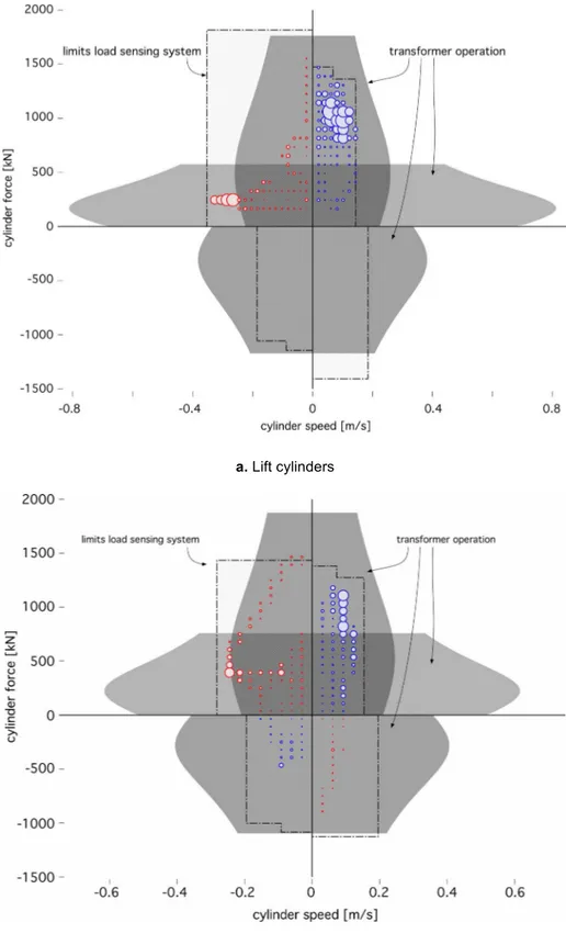
a. Lift cylinders
b. Tilt cylinders
Figure 9: Operating points of the lift (a) and tilt (b) cylinders. The size of the circles indicate the amount of energy usage
for the various grid points. Also indicated are the operational areas and limits of the conventional load sensing system (pressure limit 240-260 bar) and the new CPR-system with hydraulic transformers at a supply-pressure of 200 bar.
Efficient hydraulic pumps, motors and transformers for hydraulic hybrid systems in mobile machinery 12 For the work hydraulics, similar plots can be made (Figures 9a and 9b). Between the transformer and the cylinder a set of 4 logic valves determines which side of the cylinder is pressurised (see Fig. 5). This can be the rod side of the cylinder, the bottom side of the cylinder, or the rod and the bottom side. This results in three operating modes (the three grey areas in Figures 9a and 9b). In addition, the valves between the transformer and the cylinder can be used for a lock-up or a free-floating movement. The diagrams of Figure 9 also show the working areas for the conventional load-sensing system and the energy usage for the vari-ous load points of the short loading cycle. Both the lift and the tilt cylinders have a considerable recuperation potential (the circles in the upper left quadrant of both diagrams). As seen in Figures 9a and 9b the trans-former system has different characteristics and therefore also different limitations in its working region. The selected sizes for this study yields an operating region which is more limited in the overrunning load quad-rants but has instead a much larger working region in the dissipative load quadquad-rants. Sizing the transformers and the cylinders differently can of course alter these limits, but for this study the resulting operating region was considered a good compromise.
7. Energy use for the short loading cycle
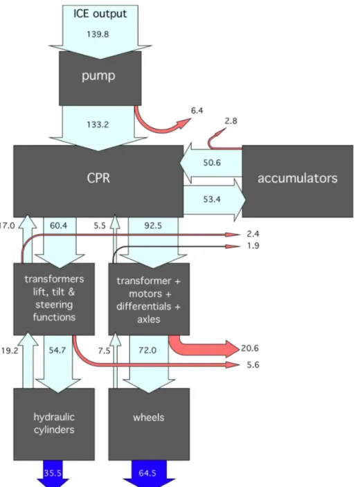
Figures 10 and 11 show the energy usage and losses of the wheel loader performing the Y-cycle for the conventional system and the CPR-system. The energy consumption is normalised, thereby setting the total net energy demand at the load to 100 (35.5 + 64.5 = 100). About two thirds of the energy is needed for the drive function. The rest is needed for the work and steering hydraulics. The energy for the fan drive and the brake accumulators is not included in this analysis. Both Sankey-diagrams only show the energy flow be-tween the engine and the load. The fuel consumption of the engine is analysed as well and will be discussed later.
The efficiency of the conventional system is poor. About 64% is lost in the hydraulic system and the me-chanical transmission. The conventional system does not have any opportunity for storing energy. According to the measurements, 8.7 units are lost in the friction brakes. Another 2.6 units go back to the transmission and are dissipated in the torque converter. Compared to the energy, which is supplied to the wheels (75.8 units), 15% is lost due to braking ((8.7 + 2.6)/75.8 x 100% = 15%). More, and much higher losses are coming from the planetary gears, the differentials and especially the torque converter. About 53% of the total transmission energy input is dissipated as heat (in the torque converter, gearbox and axels) The losses of the hydraulic circuit are even higher. More than 70% of the energy input to the hydraulic circuit is dissipated in the valves and the pumps. Also most of the regenerative energy of the hydraulic cylinders is throttled in the load sensing system.
The CPR-system performs much better. The total efficiency (excluding the diesel engine) is increased from 35.5% to 71.5%, resulting in about half the energy demand of the original system. The largest improvement is at the implement system, controlling the hydraulic cylinders. The transformers and the accumulators allow an almost complete regeneration and recuperation of the energy, which is sent back by the implements (19.4 out of 54.7 units). Furthermore the throttling losses of the load sensing system are avoided. Finally, the floating cup pump has a higher efficiency and is operated at better operating conditions than the variable displacement pumps of the original system.
On the propulsion side, the improved efficiency is mainly due to the removal of the torque converter. There is also some gain from recuperating the brake energy of the loader, but this effect is offset by the losses of
Efficient hydraulic pumps, motors and transformers for hydraulic hybrid systems in mobile machinery 13 the hydraulic transformer and hydraulic motors. Furthermore the losses of the gearbox between the torque converter and the transfer case are also eliminated. What remains are the losses of the transfer case, the differentials and the planetary gear transmissions in the axles. It is certainly an option to have the hydraulic motors installed in the axles, thereby removing the transfer case, the axles and the differentials. This would first of all eliminate the weight, costs and losses of these components. Furthermore, it would also take away the space constraints of the mechanical drive train. However, this option was not chosen in this study and will have to be investigated in another project.
Efficient hydraulic pumps, motors and transformers for hydraulic hybrid systems in mobile machinery 14 The new CPR-system results in a different engine operation. Figure 12 shows the torque-speed diagram of the diesel engine. The circles represent the engine operation for the conventional and the CPR-system. As before, the size (i.e. area) of the circles is an indication for the fuel consumption in each grid point. Both sys-tems result in an engine operation predominantly at high loads. The engine efficiency is high for most of these operating points, and the average engine efficiency is about equal for both systems. With the CPR-system, the engine is only operated if this is needed for the state-of-charge control of the hydraulic accumu-lator. There are operating conditions at which the accumulators have a sufficient charge to drive the loader and the engine can be switched off completely, or, alternatively, could run idle. In this analysis the engine is kept running at idle conditions, using a by-pass valve for circulating the oil flow from the pump. The idle losses are included in the analysis.
Efficient hydraulic pumps, motors and transformers for hydraulic hybrid systems in mobile machinery 15 With the new CPR-system, the average engine power is reduced from 195 kW for the conventional drive train to 101kW for the CPR-system. The fuel consumption is reduced by 51.4%, mainly due to the strongly reduced losses in the load sensing system and the torque converter.
It should be noted that in the conventional system, the engine efficiency is related to the efficiency of the mechanical transmission and the hydraulic circuit: high losses in the transmission result in high engine loads, which improves the engine efficiency. The other way around, a reduction of the losses in the trans-mission and the hydraulic system will result in lower engine loads, which will have an adverse effect on the average engine efficiency. This is at least true for a system in which there are no accumulators and the en-gine torque and speed is directly coupled to the load and speed demands of the loader and the implements. In the CPR-system, however, the engine is decoupled from the loads, which creates the best of both worlds: a strong reduction of the losses in the transmission and the hydraulic system, and a high average engine efficiency.
Figure 12: Fuel consumption in the operating area of the diesel engine. The size (i.e. area) of each circle
represents the amount of fuel used at the corresponding engine speed and torque.
The reduced average engine power and the reduction of the hydraulic and mechanical losses, result in a strong reduction of the cooling requirements. During the short loading cycle the conventional system re-quires an average cooling power of about 160 kW for the engine and 120 kW for the losses of the
transmission and the hydraulic circuit. With the new CPR-system, the cooling power is reduced to 80 kW for the engine and 24 kW for the transmission and the hydraulic circuit. The reduced cooler requirements will reduce the energy and power demand of the fan drive, but also reduce the weight, volume and investment cost of the coolers. This will be offset by the additional weight of the accumulators, but the net effects need to be investigated in another study.
Efficient hydraulic pumps, motors and transformers for hydraulic hybrid systems in mobile machinery 16
8. Conclusions
A detailed simulation of a large 33 metric ton wheel loader has been performed in which two systems have been examined side by side:
• The conventional mechanical transmission for driving the wheel loader and the conventional hydraulic circuit for the work and steering cylinders
• The new CPR-system with accumulators for energy recuperation and power management, and hydraulic transformers for the speed and load control of the loader and the work and steering cylinders.
The analysis has been performed on the basis of detailed measurements of the relevant load processes. The study has been limited to the short loading cycle of the loader.
The fuel consumption, the engine power and the cooler demands of a wheel loader can be reduced strongly without sacrificing the performance of the vehicle. In the analyzed cycle, the fuel consumption is reduced by more than 50%, most and for all by eliminating the losses of the torque converter and the load sensing sys-tem. The increased efficiency of the transmission and the hydraulic system does not have a negative effect on the engine efficiency. In the new CPR-system, the engine is de facto decoupled from the loads and is only operated close to the best efficiency point. The average engine efficiency for both systems is about the same. Contrary to the conventional system, the new CPR-system allows energy recuperation of the drive and implement functions. But in this analysis the amount of brake energy of the vehicle is not high, and the efficiency gained by recuperation is offset by the extra losses in the hydraulic transformers, valves, pumps, motors and accumulators. For the tilt and lift functions the recuperation potential is higher.
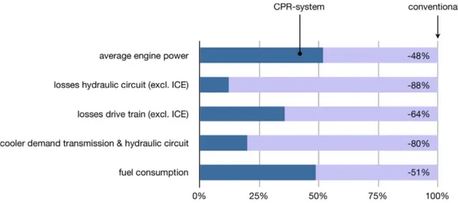
Figure 13: Relative improvement of power demands and fuel consumption in the short loading cycle, based on
simula-tion of the CPR system relative to measured data collected from the convensimula-tional system.
The CPR-system is an alternative transmission. It does not compete with battery-electric solutions nor does it exclude the use of batteries in the future. The purpose of the CPR-system is to reduce the losses and im-prove the efficiency of the wheel loader before considering expensive solutions like batteries. The CPR-system is certainly less expensive than comparable hybrid electric solutions. The weight and cost conse-quences of the new system will be limited since the torque converter, the gear shift box and the three
Efficient hydraulic pumps, motors and transformers for hydraulic hybrid systems in mobile machinery 17 hydraulic pumps are replaced by components which have about the same weight and costs. The extra weight and costs off the accumulators will increase the cost of the CPR-system, but the potential reduction of installed cooling capacity might offset these extra costs to some extent.
Efficient hydraulic pumps, motors and transformers for hydraulic hybrid systems in mobile machinery 18
References
[1]
Masami Ochiai, Shohei Ryu (2008) Hybrid in construction machinery, Proc. of the 7th JFPS Int. Sym-posium on Fluid Power, Toyama, Japan, Sept 15-18, 2008[2]
Reno Filla (2008), Alternative system solutions for wheel loaders and other construction equipment, 1st Int. CTI Forum Alternative and Hybrid Drive Trains, Berlin, Germany, Dec. 4-5, 2008[3]
Jan-Welm Biermann, Jan Hammer (2010), Jetzt auch noch Hybridantriebe bei Flurförderzeugen?, VDI-FVT-Jahrbuch 2010, pp. 22-28[4]
Thorsten Van der Tuuk, Walter Burow, Marco Brun (2009), Elektrische Hybridantriebe für mobile Ar-beitsmaschinen, 2. Fachtagung des VDMA und der Universität Karlsruhe (TH), Feb. 18, 2009, pp. 139-150[5]
Dongyun Wang, Cheng Guan, Shuangxia Pan, Minjie Zhang, Xiao Lin (2009) Performance analysis of hydraulic excavator powertrain hybridization, Automation in Construction 18 (2009) pp. 249–257[6]
Finpro (2010) EV technologies in Working Machinery – Global view[7]
Tae-Suk Kwon, Seon-Woo Lee, Seung-Ki Sul, Cheol-Gyu Park, Nag-In Kim, Byung-il Kang, Min-seok Hong (2010) Power Control Algorithm for Hybrid Excavator With Supercapacitor, IEEE Transac-tions on industry applicaTransac-tions, Vol. 46, No. 4, July/August 2010, pp, 1447-1455.[8]
Tianliang Lin, Qingfeng Wang, Baozan Hu, Wen Gong (2010) Development of hybrid powered hy-draulic construction machinery, Automation in Construction 19 (2010) 11–19[9]
Markus Kliffken, Christine Ehret, Matthias Beck, Robert Stawiarski (2009) Kosten bremsen und Um-welt schonen mit hydraulischem Hybridantrieb, ATZ Off Highway, Special edition ATZ, March 2009 p. 37-47[10]
Markus Kliffken, Detlef van Bracht, Christine Ehret, Bernhard Langenbeck (2009) Hydrostatic variable and regenerative drive train architectures for mobile machinery, Proc. of the fifth International Com-mercial Powertrain Conference ICPC, Graz, Austria, April 28-29, 2009[11]
S. Hui, J. Junqing (2010) Research on the system configuration and energy control strategy for paral-lel hydraulic hybrid loader, Automation in Construction, Vol. 19, No. 2, March 2010, pp. 213-220[12]
Karl Pettersson (2009) Secondary Controlled Swing Drive, Linköping University, Linköping, Sweden Thesis LIU-IEI-TEK-A--09/00549--SE[13]
Peter Achten (2008) A serial hydraulic hybrid drive train for off-road vehicles, NCFP I08-19.2., Tech-nical Conference IFPE, Las Vegas, USA, March 12-14 2008[14]
Georges Vael, Peter Achten, Zhao Fu (2000) The Innas Hydraulic Transformer The Key to the Hydro-static Common Pressure Rail, SAE2000-01-2561, Int. Off-Highway & Powerplant Congress &Exposition, September 2000, Milwaukee, WI, USA
[15]
Georges Vael, Peter Achten, Martin Inderelst, Hubertus Murrenhoff (2009) Hydrid-Antriebe für Gabel-stapler, 2. Fachtagung des VDMA und der Universität Karlsruhe (TH). 18.02.2009[16]
Triet Hung Ho, Kyoung Kwan Ahn (2009) Saving Energy Control of Cylinder Drive Using Hydraulic Transformer Combined with An Assisted Hydraulic Circuit, ICROS-SICE Int. Joint Conference 2009, August 18-21, 2009, Fukuoka International Congress Center, JapanEfficient hydraulic pumps, motors and transformers for hydraulic hybrid systems in mobile machinery 19
[17]
S. Sgro, M. Inderelst, H. Murrenhof (2010) Energy efficiency of mobile working machines, Proc. 7th Int. Fluid Power Conference, 7.IFK, March 22-24, 2010[18]
Yanli Chen, Shun'an Liu, Tao Shang, Jialin Liu, Yuankun Zhang, Dantong Xie (2011) Research on Control Strategy for Energy-Saving Optimization Algorithm of the Hydraulic Hybrid Vehicle, Advanced Materials Research Vols. 201-203 (2011) pp 2229-2237[19]
M. Kagoshima, T. Nanjo, and A. Tsutsui (2007) Development of new hybrid excavator. Kobelco Tech-nology Review No. 27, 2007[20]
Peter Achten, Zhao Fu, Georges Vael (1997) Transforming future hydraulics- a new design of a hy-draulic transformer, Proc. of the Fifth SICFP ’97, part 3, Linköping University, Sweden[21]
Peter Achten, Jan-Ove Palmberg (1999) What a difference a hole makes – the commercial value of the Innas Hydraulic Transformer, Proc. of the Sixth Scandinavian Int. Conf. on Fluid Power, SICFP’99, May 26-28, 1999, Tampere, Finland[22]
Peter Achten, Titus van den Brink, Timo Paardenkooper, Thomas Platzer, Jeroen Potma, Marc Schellekens, Georges Vael (2003) Design and testing of an axial piston pump based on the floating cup principle, Proc. of the Eighth Scandinavian Int. Conf. on Fluid Power, SICFP’03, May 7-9 2003, Tampere, Finland[23]
Peter Achten, Joop Somhorst, Robert van Kuilenburg, Johan van den Oever, Jeroen Potma (1999) CPR for the hydraulic industry- The new design of the Innas Free Piston Engine, Hydraulikdagarna 99, May 18-19 1999, Linköping University, Sweden[24]
Peter A.J. Achten (2007) Changing the paradigm, Proc. SICFP’07, May 21-23, 2007, Tampere, Fin-land[25]
Achten P., T. van den Brink, J. Potma, M. Schellekens, G. Vael (2009) A 4-quadrant hydraulic trans-former for hybrid vehicles, The 11th Scandinavian International Conference on Fluid Power,SICFP’09, June 2-4, 2009, Linköping, Sweden