Non-Local Modelling of Strain Softening in
Machining Simulations
To cite this article: Olufunminiyi Abiri et al 2017 IOP Conf. Ser.: Mater. Sci. Eng. 225 012053
View the article online for updates and enhancements.
José César de Sá, Erfan Azinpour and Abel Santos
Scattering from a separable, non-local potential
R L Cassola and R D Koshel
-Numerical investigation of non-local electron transport in laser-produced plasmas
Dong Ya-Lin, Zhao Bin and Zheng Jian
Olufunminiyi Abiri1,Dan Wedberg3, Ales Svoboda2, and Lars-Erik Lindgren2 1
Institute of Intelligent Systems, University of Johannesburg, Auckland Park 2006, South Africa
2
Luleå University of Technology, 971 87, Luleå, Sweden 2
AB SandvikCoromant, 811 81, Sandviken, Sweden
olufunminiyia@uj.ac.za
Abstract. Non-local damage model for strain softening in a machining simulation is presented
in this paper. The coupled damage-plasticity model consists of a physically based dislocation density model and a damage model driven by plastic straining in combination with the stress state. The predicted chip serration is highly consistent with the measurement results.
1. Introduction
The introduction of strain or thermal softening to a material model gives rise to localized deformation. Local models need to be enriched to model the strain localization problems. An enrichment with a physical attraction is the non-local model, as discussed in previous studies [1]. Non-local models incorporate a characteristic length scale that can be related to the width of the localized zone. This enables a mesh-independent solution in the finite element analysis. However, its implementation in commercial codes requires simplification of the formulations due to the limitations in available user routines.
This work is concerned with the implementation of a non-local damage model in a commercial code, MSC.Marc[2] to be used for machining simulations. Thus, the ability to combine the implementation with remeshing is important. This approach is based on a previous study of the stability and accuracy of various simplifications required in the current context [3]. The plastic behaviour of the material is described by a physically based dislocation density plasticity model [4]. A damage model is coupled to this plasticity. Damage evolution takes into account the stress state and plastic strain of the material. In this paper, the simulation results show the effect of characteristic length scale in the damage model in terms of chip formation and its serrations.
2. Non-local damage modelling of strain softening
2.1. Damage – hypoelastic plasticity
Based on the local approach of fracture described in [5], the isotropic damage variable is considered to be the softening internal variable. Strain softening is then achieved by the use of effective stress, which is obtained as a transformation of the Cauchy stress as
Non-Local Modelling of Strain Softening in
Machining Simulations
2
σ
=σ
1 − h
ω
(1)
where is a material parameter that differentiates between the damage behaviour in the tensile stress state and compressive stress state. In the case of tension, , Equation (1) reduces to its standard form as in [6].
The constitutive law of the undamaged material includes the damaged fraction by replacing the stress with the effective stress. This is possible because damage is considered to be the fraction of the material that does not transmit force/stress. The employed constitutive laws are summarized in Table 1, where is the elastic material fourth order tensor. and are the elastic and plastic spatial velocity gradients, respectively. The right superscript denotes an objective stress rate. The effective stress given by Equation (1) is used in the yield criterion when determining the amount of plastic strain. Thus, is the von Mises stress of the effective stress tensor. is the yield limit for undamaged material. The scalar is termed the plastic multiplier and corresponds to the rate of the effective plastic strain in the current plasticity model.
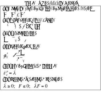
Table 1. Constitutive model. (i) Additive split of the rate of deformation tensor (ii) Hypoelastic stress update
(iii) Yield criterion (iv) Plastic flow rule
(v) Rate of hardening variable (vi) Loading-unloading condition
2.2. Non-local damage model
The non-local formulation introduces a length scale by assuming that the state variables of the material constitutive equation not only depend on its local values at x but also depend on the values of one or several of the state variables in the domain around x. The size of this domain is the length scale parameter. The influence of this neighbourhood is accounted for by defining an integral of the non-local state variable vnl, as introduced in a previous study [7] as
(2)
vlrepresents the local state variable in the continuous mechanics model. is a weighting function, and
is the material volume around the point , in which is not equal to zero.
It is assumed that the damage only evolves in the presence of plastic strain and tensile stress, as discussed in [8].
The rate of damage accumulation is given by
0 ≤ h ≤ 1
h = 1
C
ed
ed
p ∇d = d
e+ d
pσ
∇= 1−
(
ω
)
C
e: d
eF
=
σ
e−
σ
y&
ε
p e= &
λ
∂F
∂
σ
ev
nl(
x) =
r
Φ(
x −
r
′
r
x)v
l(
r
x )d
′
x
′
Ω(∫
x )r Φ Ω( )
xr Φ(3)
where includes the Cauchy stress triaxiality factor .
is the accumulative plastic strain rate in tension, i.e., when , which is a simpler approach than splitting the stress tensor into positive and negative parts [9]. The term
(4)
is affected by the normalizedLode-angle . This normalised angle in combination with the stress triaxiality characterise the stress state and is defined in [10] as
(5)
where and are the second and third invariant of . corresponds to axisymmetric tension, corresponds to plain strain or generalised shear loading and corresponds to axisymmetric compression [11]. The normalised lode angle has been found to characterize the influence of shear on damage [12]. In Equation (4), . is an additional parameter to the original Lemaitre damage model [13]. Further variables in Equation (3) are , which is the effective plastic strain at damage initiation, and , which is the effective plastic strain at failure.
In non-local averaging, the internal variables are the best candidates when compared to other variables, such as the stress and total strain tensors [14]. The constitutive equation is formulated using non-local damage . This is obtained by replacing the effective plastic strain in Equation (3) by its corresponding non-local variable using Equation (2).
3. Experiments
The plastic deformation of AISI 316L stainless steel (see Table 2) at room and elevated temperatures was characterized using dynamic compression tests by means of a Split Hopkinson Pressure Bar (SHPB). The tests were performed with a maximum strain rate and temperature of 9000 s-1 and 900 0
C, respectively. The stress-strain curves were used to calibrate the dislocation density model temperature dependent parameters. The parameters can be found in [15]. The plasticity model was used in the cutting simulations.
The geometry of the formed chips was obtained through quick-stop tests using equipment developed by SandvikCoromant. The chips show some serrations. The insert geometry is designed with an edge radius of 60 , a primary land of 0.15 mm and a chip rake angle of -60. The cutting parameters consist of a cutting speed of 180 m/min and a feed of 0.15 mm/rev. The cutting depth was chosen to be 3 mm. This test case is used in finite element simulation in this paper, with the addition of strain softening.
Table 2.Chemical composition of AISI 316L (wt %).
C Si Mn P S Cr Mo Ni V N
0.009 0.31 1.71 0.031 0.023 16.86 2.04 10.25 0.048 0.040
4. Finite element simulations
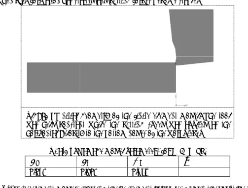
The cutting simulation is performed using the MSC.Marc [16]. The finite element simulation is modelled as a coupled mechanical and heat transfer analysis. The model is shown in Figure 1. The
Rv= 2 3 1+ v
(
)
+ 3 1− 2v(
)
(
σh σe)
2σ
hσ
e&
ε
ep+σ
hσ
e≥ 0
Rθ=
1
α
1+
α
2θ
2(
)
θ(
−1 ≤θ ≤ 1)
θ
=1−
2
π
arccos
27
2
J
33J
2(
)
3
J2 J3σ
θ = 1 θ = 0 θ = −1α
2 = 1 −(
α
1)
α
1ε
fε
r %ω
4 workpiece length is 8 mm, and its
tool with triangular thermo-mechanical plane
elastic. The initial model is composed of 900 elements in the workpiece and 2298 elements in the The thermal and mechanical properties are given in
detail.
The plasticity model was implemented in user routine WKSLP, whereas the non model was implemented in UDAMAG
robustness in cutting simulations, as different plasticity models can be coupled with different damage models. The parameters used for the Lemai
316L. The material parameters are presented in
chosen as 0.001, so that nearly no damage accumulates during compression
Chip formation is achieved via the continuous remeshing of the finite element mesh. There is no criterion for chip separation in the model. The remeshing is crucial
as the analysis involves excessive deformations and strain localization in the cutting zone. The lowest bound for an element size in the workpiece is 2.5
element edge in the tool-chip contact interface. The maximum number of elements in the simulations is fixed at 20,000. To prevent severe element distortion, the mesh was updated every fourth increment. The element edge length determines the mesh refinement in the cutting s
element edge length determines the mesh refinement in the cutting simulations. The meshes used in the simulations are described in
Table 4. The numerical solution applies an adaptive time stepping procedure. The time step is 10 seconds when chip formation has started and cutting forces become stable
Figure 1. Initial geometry of the finite element model. The tool was held constant while the cutting speed was applied as the horizontal velocity to the bottom nodes of the workpiece
Table 3. Damage model parameters for AISI 316L. 0.035
Table 4. Finite element models showing the refinement variables used in the adaptive meshing.
ε
fMesh refinement notation
Mesh1 Mesh2
workpiece length is 8 mm, and its height is 1.6 mm. The workpiece is meshed using a quadrilateral mechanical plane-strain elements. The tool is assumed to be thermo elastic. The initial model is composed of 900 elements in the workpiece and 2298 elements in the The thermal and mechanical properties are given in [15], in which the plasticity model is described in
The plasticity model was implemented in user routine WKSLP, whereas the non
s implemented in UDAMAG [16]. The separate implementation allows for additional robustness in cutting simulations, as different plasticity models can be coupled with different damage models. The parameters used for the Lemaitre model in Equation (3) are obtained from
316L. The material parameters are presented in Table 3. The material constant in Equation early no damage accumulates during compression [8].
Chip formation is achieved via the continuous remeshing of the finite element mesh. There is no criterion for chip separation in the model. The remeshing is crucial for the stability of the simulation, as the analysis involves excessive deformations and strain localization in the cutting zone. The lowest bound for an element size in the workpiece is 2.5 . This size is equivalent to the shortest tool chip contact interface. The maximum number of elements in the simulations is fixed at 20,000. To prevent severe element distortion, the mesh was updated every fourth increment. The element edge length determines the mesh refinement in the cutting simulations. The element edge length determines the mesh refinement in the cutting simulations. The meshes used in numerical solution applies an adaptive time stepping procedure. The time step is 10 when chip formation has started and cutting forces become stable.
Initial geometry of the finite element model. The tool held constant while the cutting speed was applied as the horizontal velocity to the bottom nodes of the workpiece.
. Damage model parameters for AISI 316L.
0.502 0.395 1
Finite element models showing the refinement variables used in the adaptive meshing.
h
ε
rω
cα1
Mesh refinement Refinement variable, element edge length ( )
Number of elements at steady state
100 12100
75 15200
height is 1.6 mm. The workpiece is meshed using a quadrilateral strain elements. The tool is assumed to be thermo-elastic. The initial model is composed of 900 elements in the workpiece and 2298 elements in the tool.
, in which the plasticity model is described in The plasticity model was implemented in user routine WKSLP, whereas the non-local damage . The separate implementation allows for additional robustness in cutting simulations, as different plasticity models can be coupled with different damage are obtained from [17] for AISI in Equation (1) is Chip formation is achieved via the continuous remeshing of the finite element mesh. There is no for the stability of the simulation, as the analysis involves excessive deformations and strain localization in the cutting zone. The lowest . This size is equivalent to the shortest tool chip contact interface. The maximum number of elements in the simulations is fixed at 20,000. To prevent severe element distortion, the mesh was updated every fourth imulations. The element edge length determines the mesh refinement in the cutting simulations. The meshes used in numerical solution applies an adaptive time stepping procedure. The time step is 10-6
Finite element models showing the refinement variables used in the adaptive meshing. Number of elements
5. Results
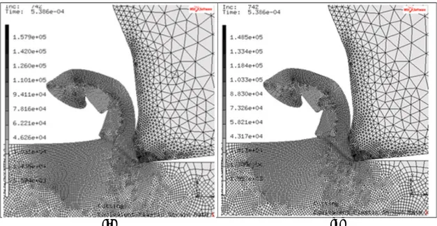
Figure 2 shows a comparison between simulations based on Mesh2 using local damage and non damage models. The result is very similar to that expected when the el
of . The element sizes are approximately
deformation of the local model as the localization is further enhanced by smaller elements. This notorious mesh dependency is remedied when using
(a)
Figure 2. Effective plastic strain rate using a fine mesh with (a) thermal and strain softening using a local damage model and (b) thermal and strain softening using a non
6. Conclusions
A non-local damage model of strain softening in machining simulations has been implemented into a commercial code, MSC.Marc [2].Chip serrations are predicted using the model.
updating [19] is used as it simplifies the implementation of the non also reduces the non-linearity of the non
cost of small time steps. Acknowledgements
The financial support of the strategic innovation programmeLIGHTer provided by VINNOVA and TETFUND Abuja is acknowledged.
the University of Johannesburg via the Global Excellence and Stature (GES) fellowship granted to the first author.
References
[1] Bazant ZP, Jirásek M. Nonlocal integral formulations of plasticit progress. J Eng Mech 2002;128(11):1119
[2] Marc M, Volume A. Theory and user information. MSC Corp 2007.
[3] Abiri O, Lindgren L. Non-local damage models in manufacturing simulations. European Journal of Mechanics-A/Solids 2015;49:548-560.
[4] Lindgren L-, Domkin K, Hansson S. Dislocations, vacancies and solute diffusion in physical based plasticity model for AISI 316L. Mech Mater 2008;40(11):907
[5] Besson J, Moinereau D, Steglich D. Local approach to fracture. : Presses
shows a comparison between simulations based on Mesh2 using local damage and non damage models. The result is very similar to that expected when the elements resolve at a length scale
. The element sizes are approximately . Refining the mesh will change the deformation of the local model as the localization is further enhanced by smaller elements. This notorious mesh dependency is remedied when using a non-local model [3,18].
(b)
local damage model of strain softening in machining simulations has been implemented into a Chip serrations are predicted using the model. Explicit non simplifies the implementation of the non-local damage model. The model
he non-local formulation and therefore makes it more robust at the
The financial support of the strategic innovation programmeLIGHTer provided by VINNOVA and .The authors also gratefully acknowledge the financial support of the University of Johannesburg via the Global Excellence and Stature (GES) fellowship granted to the
[1] Bazant ZP, Jirásek M. Nonlocal integral formulations of plasticity and damage: survey of progress. J Eng Mech 2002;128(11):1119-1149.
[2] Marc M, Volume A. Theory and user information. MSC Corp 2007.
local damage models in manufacturing simulations. European Journal of 560.
, Domkin K, Hansson S. Dislocations, vacancies and solute diffusion in physical based plasticity model for AISI 316L. Mech Mater 2008;40(11):907-919.
[5] Besson J, Moinereau D, Steglich D. Local approach to fracture. : Presses des MINES; 2006.
shows a comparison between simulations based on Mesh2 using local damage and non-local ements resolve at a length scale . Refining the mesh will change the deformation of the local model as the localization is further enhanced by smaller elements. This
. Effective plastic strain rate using a fine mesh with (a) thermal and strain softening using a local damage model.
local damage model of strain softening in machining simulations has been implemented into a xplicit non-local local damage model. The model more robust at the
The financial support of the strategic innovation programmeLIGHTer provided by VINNOVA and gratefully acknowledge the financial support of the University of Johannesburg via the Global Excellence and Stature (GES) fellowship granted to the
y and damage: survey of
local damage models in manufacturing simulations. European Journal of , Domkin K, Hansson S. Dislocations, vacancies and solute diffusion in physical based
des MINES; 2006. . Effective plastic strain rate using a fine mesh with (a) thermal and strain softening using a cal damage model and (b) thermal and strain softening using a non-local damage model.
6
[6] Simo J, Ju J. Strain-and stress-based continuum damage models—I. Formulation. Int J Solids Structures 1987;23(7):821-840.
[7] Bažant Z, Lin F. Non‐local yield limit degradation. Int J Numer Methods Eng 1988;26(8):1805-1823.
[8] Pirondi A, Bonora N. Modeling ductile damage under fully reversed cycling. Computational Materials Science 2003;26:129-141.
[9] Desmorat R, Cantournet S. Modeling microdefects closure effect with isotropic/anisotropic damage. Int J Damage Mech 2008;17:65-96.
[10] Cao T, Gachet J, Montmitonnet P, Bouchard P. A Lode-dependent enhanced Lemaitre model for ductile fracture prediction at low stress triaxiality. Eng Fract Mech 2014;124:80-96.
[11] Xue L, Wierzbicki T. Ductile fracture initiation and propagation modeling using damage plasticity theory. Eng Fract Mech 2008;75(11):3276-3293.
[12] On the development and identification of phenomenological damage models-Application to industrial wire drawing and rolling processes. Key Engineering Materials: Trans Tech Publ; 2013. [13] Lemaitre J. A continuous damage mechanics model for ductile fracture. Journal of Engineering Materials and Technology 1985;107(1):83-89.
[14] Andrade FXC, de Sá JC, Pires FA. Assessment and comparison of non-local integral models for ductile damage. Int J Damage Mech 2014;23(2):261-296.
[15] Svoboda A, Wedberg D, Lindgren L. Simulation of metal cutting using a physically based plasticity model. Modell Simul Mater Sci Eng 2010;18(7):075005.
[16] MSC. Marc® Software Manual Volume D: User Subroutines and Special Routines (Version 2007). ; 2007.
[17] Mkaddem A, Gassara F, Hambli R. A new procedure using the microhardness technique for sheet material damage characterisation. J Mater Process Technol 2006;178(1):111-118.
[18] Abiri O, Svoboda A, Lindgren L, Wedberg D. Controlling thermal softening using non-local temperature field in modelling machining. Journal of Machining and Forming Technologies 2016;Submitted.
[19] Abiri O, Lindgren L. Non-local damage models in manufacturing simulations. European Journal of Mechanics A/Solids 2015;49:548-560.