Faculty of Technology and Society
Master thesis
Proof-of-concept of Model-based testing based on an
UML-model of a water-level measurement system
Zoubida Alshekhly
Namra Jamshaid Gill
Exam: Computer Science, Master’s Programme (One Year) Subject Area: Computer Science
Abstract
Software testing is a very important phase in software development as it minimize risks in a software system, however, it consumes time and can be very expensive. With automatic test case generation time consumption and cost can be reduced. Model-based testing is a method to test a software system with a model of the systems behaviour. Automatic test case generation is often considered a favorable support in model-based testing. In this work, the concept of model-based testing is explored along with testing the embedded part of a water-level measurement system (WLM) to investigate the efficiency of model-based testing on a software system. As a result of this, a model-based testing tool, MoMut::UML is used to generate the test-cases on the UML model of WLM system that is built in a UML modeling environment, Eclipse-Papyrus. However, MoMut::UML implements a special type of model-based testing technique, model-based mutation testing; that injects faults in the UML model, and generates test-data on the fault-based model. By this, the behaviour of system-under-test, only the UML model of water-level measurement system, is tested.
Keywords: Model-based testing, Model-based testing tool, software system, UML, auto-matic test case generation.
Glossary
LORAWAN: The LoRaWAN specification is a Low Power, Wide Area (LPWA) network-ing protocol designed to wirelessly connect battery operated ‘thnetwork-ings’ to the internet in regional, national or global networks, and targets key Internet of Things (IoT) require-ments such as bi-directional communication, end-to-end security, mobility and localization services.
System under test (SUT):System under test refers to a system that is being tested for correct operation.
Test oracles:Test oracle, is a mechanism for determining whether a test has passed or failed.
The Object Constraint Language (OCL): is a declarative language describing rules applying to Unified Modeling Language (UML) models.
Contents
1 Introduction 1
1.1 Background . . . 1
1.2 Vision of this work . . . 2
1.3 Contribution and novelty of this work . . . 2
1.4 Motivation of using water-level measurement system . . . 2
1.5 Research aim and research questions . . . 3
1.5.1 Research aim . . . 3
1.5.2 Research question (RQ) . . . 3
1.6 Scope and limitations . . . 3
1.6.1 Research limitations . . . 3
2 Theoretical background 4 2.1 Automatic testing on software systems . . . 4
2.2 Model-Based Testing . . . 4
2.3 UML (Unified Modeling Language) . . . 5
2.4 Model-based testing test criteria . . . 5
2.5 Model-based testing tools . . . 6
3 Related work 7 3.1 Experiences of System-Level Model-Based GUI Testing of an Android Ap-plication . . . 7
3.2 Model Based Testing of System Requirements using UML Use Case Models 7 3.3 An Evaluation of Model-Based Testing in Embedded Applications . . . 7
3.4 Water-level measurement system (WLM) . . . 8
4 Method 10 4.1 Nunamaker and Chen’s methodology . . . 10
4.1.1 Construction of a Conceptual Framework . . . 10
4.1.2 Development of a System Architecture . . . 11
4.1.3 Analyze and Design the System . . . 11
4.1.4 Build the System . . . 11
4.1.5 Observe and Evaluate the System . . . 11
5 Implementation 12 5.1 Problem breakdown . . . 12
5.2 MBT tool literature review . . . 13
5.3 System Architecture . . . 15
5.3.1 System Architecture of whole process . . . 15
5.4 Model-Based Testing . . . 16
5.4.1 UML model . . . 16
5.4.2 Papyrus . . . 18
5.4.3 UML model in Papyrus . . . 20
5.5 Perform Model-Based Testing . . . 23
5.5.1 Configuration of MoMut - tool . . . 24
5.5.2 Running the MoMut - tool with the AlarmSystem demo . . . 26
5.5.3 Running the MoMut - tool with the water-level measurement system 29 5.6 Model-based Test suite generation . . . 33
6 Results & Analysis 36 6.1 Analysis of Model-based testing . . . 36
6.1.1 Challenges with model-based testing tool: MoMut:UML . . . 36
6.1.2 Analysis of UML model . . . 37
6.1.3 Analysis of MBMT Test-suite generation . . . 37
6.1.4 Drawbacks of Model-based testing . . . 38
6.2 Analyse of the chosen command-line option for MoMut . . . 38
6.3 Benefits of MoMut::UML for Model-based testing . . . 39
7 Threats to Validity 39 8 Discussion & Conclusion 40 8.1 Awnsering the research questions . . . 40
8.2 Future work . . . 41
8.3 Conclusion . . . 41
References 42
9 Appendix A 45
1
Introduction
This section presents the background of this work followed by the vision, the research aim and the research questions. The vision includes the contribution, and the novelty of the work. Moreover, the scope and limitations are also presented.
1.1 Background
Testing is the evaluation process to improve the quality of a product [1]. During the execution of testing a software system, a failure can be detected. The failures are caused by faults in the software system. The faults are usually caused by human-error in design, code etc. When a failure is detected, the fault can be investigated.
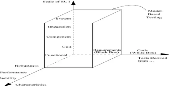
There are different types of software testing methods, techniques, and test data genera-tion. The different types of testing differ depending on their scale, characteristics and the information needed to design the tests. Examples of testing are; component testing, inte-gration testing, system testing, functional testing, robustness testing, performance testing, usability testing, black-box, white-box testing, and model-based testing which is a form of black-box testing [1]. The model-based testing generates functional tests and can be used for robustness testing. Figure 1, illustrates a graph of how the different types of testing are divided into three axis. Every axis represent an aspect in testing, the first axis represents the scale of the system under test, SUT, the second one represents which characteristics to test, and the third axis shows the type of information to test. The figure also shows how the model-based testing is related to these different axis.
Figure 1: Different types of testing
One of the fundamental factors in software testing is the automatic test case generation. Automatic Test case generation for software testing indicates a process that generates test cases automatically. The automatic test case generation technique is convincing as it re-duces the cost and time, and increase the system efficiency, when it is compared to other
test generation processes [2].
The model-based testing (MBT) technique, is one of the popular searched phrases in con-nection with automatic test case generation. Model-based testing is built with the model of a system, in order to generate test cases of the model of a system [3]. There are multiple types of models that can be used in MBT. However, the most practical and widely used model for supporting the MBT technique is the unified modeling language, UML[4]. MBT technique is used in tools that are able to generate test cases by analyzing the behavior of the UML model. Model-based testing have different test criteria, and one of these criteria is used in this work and mentioned in section 2.4 [1].
The SUT used in this work is a water level measurement system [5]. The system consists of different technical parts: embedded, dashboard as a frontend, and a network part. The MBT is performed on the embedded part of the system. The motivation for selecting the embedded system part is mentioned in section 1.4.
1.2 Vision of this work
The vision of this work is to provide a proof-of-concept of MBT. For this aim MBT is performed on an embedded system of water-level measurement system which is presented in section 3.4. Subsequently, a guide on how to implement and perform MBT is provided based on the experience developed while performing MBT.
1.3 Contribution and novelty of this work
The contribution of the work is to provide the IT industry a base to start adopting MBT by creating an easy-to-follow guide on how to implement MBT. The guide indicates a clear explanation on how to test an embedded system using a specific MBT tool. In this way, a proof-of-concept of the MBT is established to illuminate the privileges of MBT approach.
1.4 Motivation of using water-level measurement system
The motivation for using the water-level measurement system, WLM, as a test material for this work is because the system is already manually tested [5]. The automatically generated test cases are conducted by using a MBT tool. The reason behind selecting the embedded system part and not the other associated parts; the front-end part is presented as an open source dashboard, and the interface of the dashboard is not reachable for testing. The network part of the water-level measurement i.e. LoRaWAN network is also unreachable for executing test cases through MBT. Although, the embedded part of the system works as a state-machine and therefor is reasonable for MBT to test.
1.5 Research aim and research questions
1.5.1 Research aim
The aim of this work is to provide a guide that explains how to generate test cases along with a model-based testing tool. To clarify, this work is a proof-of-concept of model-based testing implemented on a embedded system with test cases generated based on the UML model.
1.5.2 Research question (RQ)
RQ1 What are the steps that should be followed to perform Model-based testing with a UML-model?
RQ2 How to use the chosen Model-based testing tool to generate testcases by using an UML-model of an embedded system?
RQ3 How to build an UML-model of the embedded system of water-level measurement system?
RQ4 Which type of Model-based testing technique is used by the chosen Model-based testing tool?
1.6 Scope and limitations
This work has limitations as the scope of MBT is broad. The research limitations are presented in the following section.
1.6.1 Research limitations
The guide on how to perform MBT with a MBT tool is done by using specifically an UML Model. Furthermore, as mentioned, the proof-of-concept will only be implied on an embedded system of WLM system. A literature review about the available model-based tools is conducted in order to choose the MBT tool for performing MBT on an embedded system. There are different type of MBT techniques presented, however, only one of them will be explored in this work.
2
Theoretical background
This chapter presents the theoretical background about the relevant topics of this work.
2.1 Automatic testing on software systems
Testing is an essential part for a software development of software system. Testing pro-vide the quality assurance of the software solution. Manual testing are usually performed on the software system solutions. Thus, as the complexity and the size of the software system grow, further more time and labor-force are required. To avoid such labor-force and minimize the time-consumption, automatic test case generation can be performed [6]. There are many reason of why test automation is beneficial compared the manual testing. According to the research analysis [7], performing automatic testing in software systems lead to: improving product quality, achieving high test coverage of code, reducing testing time, allowing the re-usability of tests, reducing cost and increasing fault detection. Per-forming automatic testing on a software system helps to provoke failures in the system [8]. By provoking faults in the system, the information about the corresponding faults are conveyed and the failures can be dealt with. The software testing process consists of three parts: test case generation, test execution, and test evaluation [6]. There are several types of automatic test case generation. The automatic test case generation approaches [9] are: specification based test case generation, model-based test case generation, path oriented test case generation and intelligent technique.
2.2 Model-Based Testing
Model-based testing (MBT) is a growing software testing technique that has many ben-eficial earnings, such as; initial specification and error detection, improving test docu-mentation and communication between the developer and testers, and lower cost[10]. As mentioned earlier in section 1.1, the model-based testing is a form of black-box testing, because the test cases are generated from a model that is obtained from of the behavior of the system under test (SUT) or its environment. MBT tests are based on the model which in turn is used by a MBT-tool that generates the test cases from it [1].
Model-based testing have four different approaches: • "Generation of test input data from a domain model." • "Generation of test cases from an environment model."
• "Generations of test cases with oracles from a behavior model." • "Generations of test scripts from abstract tests." [1]
The most used MBT approach is the third one, it focus on the SUT behavior such as; the expected output values of it. It generates test cases, as well as, generation of oracles that have the task to check the output of the SUT. This kind of testing is very efficient, because
the sequence of the generated test cases can be transformed into test scripts directly. The use of MBT can vary dependent on the system or the tool utilized. Further advantages of MBT that are good to mention; its potential to evaluate SUT quality and millions of test suites can be generated automatically [11].
2.3 UML (Unified Modeling Language)
UML is generally used as a model support for MBT. There are many advantageous rea-sons for using UML, such as; supplying a broad collection of diagrammatic notations, the Object Constraint Language (OCL) combined with UML in order to utilize more accurate models. In addition, UML is a standard for modeling, which make it qualified in order to process a MBT. UML consists of a set of diagrams [12]. Some of these diagrams can be used in MBT tool.
The UML diagrams that can be used for MBT are: class diagram, object diagram, and state machine diagram. These diagrams make a base for MBT, every diagram has a task in automatic test generation. The class diagram models the control points and SUT observa-tion, while object diagram defines the test data. The state machine and OCL collaborate to model the dynamical behavior of SUT [12]. The process of conducting an UML model that is appropriate to MBT, is by adding the details about the behaviour of the methods in a class diagram. The reason for that is the state-machine diagram does not give sufficient information about the behaviour of the SUT [1].
2.4 Model-based testing test criteria
There are different kinds of test selection criteria. These criteria determine the ability of MBT tool to control the selection of tests. The test criteria selection process depends on the data coverage of the SUT that leads to good test suites. The test criteria is based on the model and the requirement of the SUT, and not on the source code of the model. There are several types of test criteria such as data coverage criteria, fault-model criteria, requirements-based criteria etc. [1].
Data coverage criteria creates test data on specified data input values, this can be useful when there is huge number of possible input values.
Fault-based testing is a software testing technique that is done by employing the fault that occur very often. The idea of fault-based technique is to use fault models to generate test data.
Requirements-based criteria is a software testing technique that generates test-data on the functional requirements of the SUT. This is useful to verify whether the requirements of a product is fulfilled [1].
2.5 Model-based testing tools
Model-based testing tool generates test cases which can later be automatically deployed by a computer [11]. Several Model-based testing tools are available today, both commercial tools and prototypes. In order to decide which MBT approach suits best for a software system, it is important to understand which type of techniques and tools to fulfill the systems test requirements. A categorization is applied for the possible approaches [1]; the categorization is divided into following: determining the subject of the model, reflecting on the source of the test model, determining the characteristics of the model, determining the style and notation of the model, reflect on how the tool approach supports test criteria such as data coverage criteria, requirements-based criteria etc, and whether it should be online or offline testing [1].
3
Related work
This chapter presents the related works. All of the papers that are presented in this section have similarities and differences with the research in this work.
3.1 Experiences of System-Level Model-Based GUI Testing of an An-droid Application
In the IT-industry, companies hesitate to use MBT technique, because there is a lack of easy to use tools for MBT, and difficulties for finding new test model experts. However, T. Tommi, et al. [13], is aiming to find a solution for finding an user-friendly tool by develop-ing a new MBT tool used for Android system on mobile devices. The developed tool-set is called TEMA tools and it is a commercial tool. The Tema tools consist of further tools for the different aspect of MBT which are; test modeling, test design, test generation and test debugging. The SUT in Tema tools functions as a state machine. The result of Tema toolset is considerable, the modeling process is effective for finding errors. Despite the bugs found in Tema tools, it can anyway provide a maintainable regression testing when a new release is out. Additionally, the tool helps out with reducing the number of test cases by editing the model with a few steps.
The comparison between the related work and this work, is that both are aiming to use MBT to generate test cases by using a state machine. However, a new tool is developed in the related work. In addition to, T. Tommi, et al. are testing an Android application.
3.2 Model Based Testing of System Requirements using UML Use Case Models
B. Hasling et al. [14], uses a MBT tool provided by Siemens for a medical solution. The contribution is to utilize a use case model as a basis for MBT of system tests, which means combining the requirement process with a testing process by use case model. The ad-vantages of using the use case model are; reviewing models, verification and validation, improved requirements, improved test coverage, tracing to requirements and early start in the development life cycle. The tool used called TDE/UML and it is developed by Siemens. The testing team found it useful to apply MBT using use case model.
The contribution of this related work is to test only the system requirements and not the system, which make it different from this work that is testing an UML model of an em-bedded system. The other differences are B. Hasling et al. are using UML use case model, and using a TDE/UML MBT-tool for generating test cases.
3.3 An Evaluation of Model-Based Testing in Embedded Applications
S. Weißleder et al. [15] performed MBT on an embedded system to investigate the advan-tages of automatic MBT generation. The UML model is used for designing the functionality
of the system. It assumes that MBT generation process reducing 85% of costs for test de-sign. However, the aim is to prove if the value is true and if MBT is so powerful. The authors explain that the testers in the organization need to be trained into MBT, and changing the workflow from writing test cases to design models instead. In addition, the initial cost of MBT framework and tools can be a barrier. However, the exchange from a regular testing method to MBT pays off all the costs. Even though, the managers are not convinced about this and not willing for test method exchanging. The aim is reached, and MBT is an efficient testing tool as promising, although, the transformation process to MBT can be useful only for a similar case study and not for others.
The differences between this work and the related work are; it is not clear which tool is used for MBT and aims to check the efficiency of MBT. The similarities are; an embedded system is tested in both works and an UML state machine is used to present the SUT. In this related work, the researcher claims that MBT reduces test costs which is not evaluated in this work.
3.4 Water-level measurement system (WLM)
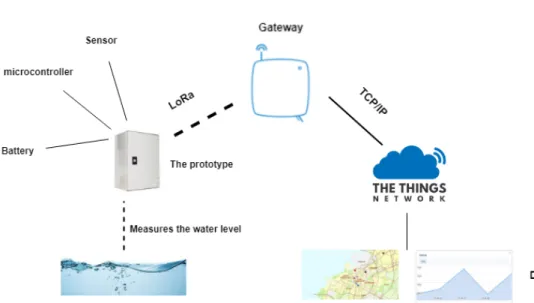
The model-based testing, MBT, is implemented on an embedded system which is a part of the water level measurement system [5]. The water level measurement system includes different parts, which are; network, dashboard as a frontend part and hardware. The main part of the entire system is hardware. The water level measurement is placed in the wells using a sensor connected to a microcontroller. The communication link between different parts is LoRaWAN, which may either be built into a microcontroller or be built separately. The rest of the hardware part for the product consists of an encapsulation box and a battery. The system is already tested manually in the lab environment, and the aim of this work is to implement an automatic test method on this system. An overview of the whole system including all the parts is shown in figure 2.
4
Method
This section explains how the research work is conducted and which research methodology is used in order to answer the research questions.
4.1 Nunamaker and Chen’s methodology
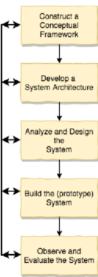
The research process of Nunamaker and Chen’s research methodology consists of five stages [16] [17]. See figure 3 below. Each stage has its own objective. If new knowledge about a specific domain is acquired by researchers, changes in already made design decisions in foregoing stages occur. The change made in foregoing stages improves the quality of the system and the research results [17]. It is why, this research methodology is “of an iterative nature” [16]. This research methodology is used in this work due to its iterative nature. As MBT is performed by analyzing the MBT tool and experimenting; going back and forth in the stages is helpful.
Figure 3: Overview of Nunamaker and Chen’s research methodology.
4.1.1 Construction of a Conceptual Framework
This is the first stage in the research process, to formulate a research question. Since Nunamaker and Chen’s research methodology is used to create the proof-of-concept, a
clear picture of what is already presented in the literature has to be understood. This is done through literature review. This is done before any formulation of a research question. The formulation together with the research aim is in section 1.3. The formulation is done through daily meetings and discussions with the supervisor. Also, the chosen MBT tool is selected through the literature review. Several MBT tools in literature and physically available are studied; in order to find a MBT tool that is most optimal to achieve the aims of this work.
Moreover, the research aim is divided into sub-goals, also called sub-problems. There-after solution for each sub-problem is allocated and presented as a problem-tree. The result of this stage can be seen in section 5.1.
4.1.2 Development of a System Architecture
The second stage in the research process is developing a system architecture, and it’s done by creating an architecture of the proof-of-concept of this work. All the associated parts are collected to make an overall system architecture such as: water-level measurement, and the MBT tool. The architecture is done by studying how the parts are related to each other and what functionality they provide. The system architecture provides an overview of all the different parts needed in MBT. The result of this stage is presented in section 5.3.
4.1.3 Analyze and Design the System
During the third stage, the UML model of the system is designed. The model is designed by studying the embedded system functionality of the WLM system. The designed UML model in this stage is build in the next stage with the chosen UML modeling environment. Moreover, the functionality of the chosen MBT tool is analyzed. The result of this stage is presented in section 5.4.
4.1.4 Build the System
In the fourth stage, MBT is performed with the chosen MBT tool. Firstly, the UML model is build and verified with the chosen UML modeling environment. Secondly, the UML model is connected to the MBT tool. Thirdly, MBT tool is executed to generate test cases. While implementing MBT, an easy-to-follow steb-by-step guide is illustrated in this stage. The result of this stage is presented in section 5.5.
4.1.5 Observe and Evaluate the System
In the last stage of Nunamaker and Chen’s research methodology, the result of the gen-erated test cases by MBT tool is presented. An evaluation of MBT approach is done depending on the result of the automatic generated test cases from the MBT-tool. See section 5.6 for the results of this stage.
5
Implementation
This section presents implementation of this work in order to create a proof-of-concept of MBT.
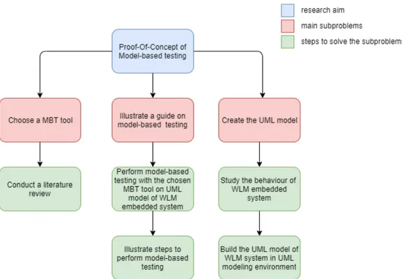
5.1 Problem breakdown
The proof-of-concept of MBT is divided into three sub-problems. In order to solve the sub-problems, solutions are allocated in some steps for each main sub-problem:
• Choosing a MBT tool
A relevant list of MBT tools is chosen. The MBT tools presented in the list are delimited by their type and input format. Only tools that have UML models as input are relevant for this work. When the literature review is done as presented in section 5.2, an experimental study is conducted on the MBT tools that are likely to be the most relevant to test UML model. As the result of this, one MBT tool is selected.
• Creating an UML model?
In order to create the UML model, the states and the state transitions are analyzed of WLM system in section 5.4.1. The UML state machine is a simple state machine with only 3 states, LOW, MEDIMUM and HIGH. The UML model is created and verified in an UML modeling environment in section 5.4.2 to use the model for MBT test case generation.
• Creating a user-friendly guide on Model-based testing?
In order to create a guide, every step done while performing MBT is illustrated in the guide. Moreover, the guide includes risks and difficulties faced while performing the test-ing. The guide is presented in a step-by-step form as a user manual.
Figure 4: Problem-tree: problem breakdown with the solutions
5.2 MBT tool literature review
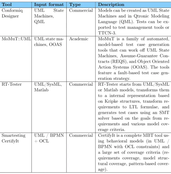
In this work, a list [18] of MBT tools is investigated. The MBT tools in the list are categorized on the basis of input-format and the type of how they are accessible. The relevant and available MBT tools from the mentioned list are presented in table 1 below.
Table 1: Relevant MBT tools and Modeling Environment
Tool Input format Type Description Conformiq
Designer
UML State Machines, QML
Commercial Models can be created as UML State Machines and in Qtronic Modeling Language (QML). Tests can be ex-ported to test management tools or TTCN-3.
MoMuT::UML UML state ma-chines, OOAS
Academic MoMuT is a family of automated, model-based test case generation tools that can work off UML State Machines, Assume-Guarantee Con-tracts (REQS), and Object Oriented Action Systems (OOAS). The tools feature a fault-based test case gen-eration strategy.
RT-Tester UML/SysML, Matlab
Commercial RT-Tester starts from UML/SysML or Matlab models, transforms them to a internal representation based on Kripke structures, transform re-quirements to LTL formulae, and generates test cases using an SMT solver based on the goals from re-quirements and various model cov-erage criteria.
Smartesting CertifyIt
UML / BPMN + OCL
Commercial CertifyIt is a complete MBT tool us-ing behavioral models (in UML / BPMN with OCL constraints) and a large set of coverage criteria (re-quirements coverage, model struc-tural coverage, pattern-based cover-age).
Three of the MBT tools, are commercial types as shown in table 1, and therefor not pos-sible to test. Conformiq Designer requires that in order to test their product the project should be associated to a company. Moreover, a request with a detailed purpose needs to be sent to the owner so they can approve the request and make the MBT tool available. Likewise, the MBT tool, RT-Tester costs and is not available immediately either. More-over, Smarttesting CertifyIt and MBTSuite [19] are not available as well. However, MBT tool, MomuT::UML is available on the site as an open source software. Aside from the list of MBT-tools mentioned above, the modeling environment PolarSys [20] is tested besides the chosen one, Papyrus. Papyrus is selected, it’s easy to use in compare with Polarsys because the user manual is present for Papyrus. The steps for implementing the UML model are illustrated in section 5.4.2. As the result of this, MoMuT::UML is chosen as the MBT tool to perform MBT, and Papyrus as a modeling environment because it is required
for MoMut::UML.
5.3 System Architecture
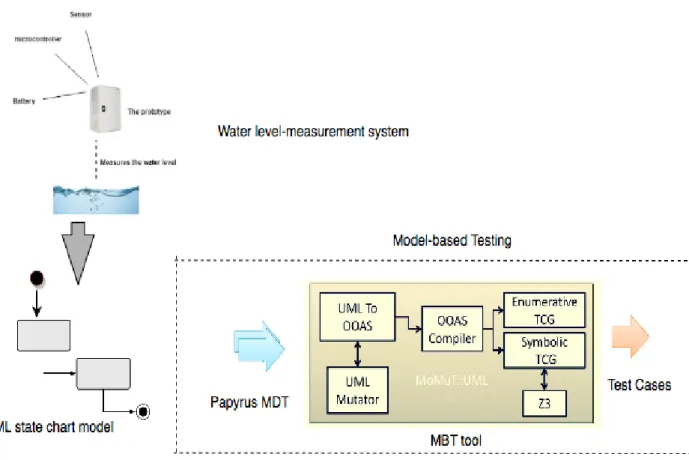
In this section, the whole process of this work is illustrated as a system architecture, with the association between the different elements; WLM system, UML model, modeling environment and MBT tool.
5.3.1 System Architecture of whole process
The abstract view of how all the parts in the MBT process are connected is shown in the system architecture presented below.
Figure 5: System Architecture of Model-Based testing
The UML model of WLM system is the SUT used for MBT. The UML model focuses on the behavior of the WLM embedded system. The MBT process starts by implementing the UML model in the UML modeling environment Eclipse Papyrus, and the UML model is thereafter verified by it. Thereafter, a "bridge" between the UML model and the MBT
testing tool MoMut::UML is built. The "bridge" is built through an UML profile1called tcg profile, which is described in section 5.5. When the MBT tool is executed, it generates test cases based on the Model-based Mutation testing technology, which is presented in section 5.4.4, in which the mutated UML model is converted into object-oriented action system language OOAS2, and two distinct test case generation back ends are used; Enumerative TCG, that runs an explicit state exploration of the SUT, and Symbolic TCG that uses symbolic techniques3. Moreover, an external back-end is used to handle more complex models called Z34. The backends are applied to the OOAS in order to generate test-cases on SUT; UML model of WLM embedded system. The whole process is illustrated in details as a guide in section 5.5.
5.4 Model-Based Testing
In this section, the elements used for MBT are presented.
5.4.1 UML model
System architecture of SUT, WLM system
The architecture shown in figure 6 demonstrates the embedded part of the WLM system and the functionality of it. The hardware components used are; battery, encapsulation box, microcontroller with LoRa connectivity and a sensor. The hardware used to give functionality to the system; the sensor measures the data, and the microcontroller reads the data from the sensor. Consequently, the data is sent from the microcontroller to the LoRa gateway[5].
1UML profile is a lightweight extension mechanism to the UML standard 2
A formalism well-suited for expressing object-oriented models of embedded systems.
3
The symbolic method is a technique for counting combinatorial objects. It uses the internal structure of the objects to derive formulas for their generating functions.
4
Figure 6: Architecture of the embedded system for the water level measurement system. Depending on the measured values from the sensor, WLM is divided in three different levels: Low, Medium and High [5]. The logic of how the system works is illustrated in Appendix A as an activity diagram.
UML state machine
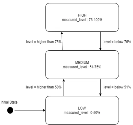
As mentioned in the previous section, the state machine of WLM system only consists of three states; LOW, MEDIUM, and HIGH. Therefore, the UML model of the WLM system is a basic UML state machine model with three states. The initial state of the SUT is set to LOW. The trigger for each event is the measured level by the sensor, depending on the water-level the transitions in the state machine are made, see figure 7 below.
Figure 7: State machine diagram of WLM system
As seen in the figure above, every state is reached when a certain percentage of water-level is measured. If the water-level is between 0-50% of the maxiumum height of e.g a well, the state is set to LOW. If the water-level exceeds to 51-75% the state is transitioned to MEDIUM, and if the water-level is measured higher than 75%, the state is transitioned to HIGH.
5.4.2 Papyrus
In order to perform MBT with MoMut::UML on WLM system, the UML model of WLM system is build in an UML modeling environment, Papyrus. Papyrus is an UML modeling environment built on the extensible Eclipse framework. It is possible to view different aspects of a system by using several diagrams in Papyrus. The diagrams are associated with the model of the system in which all modeling elements are placed. The modeling elements are used in the diagrams. It is also possible to adapt UML to specific domains by creating UML profiles in Papyrus.
The installation of Papyrus is done in several steps, firstly, the Eclipse standard has to be installed, thereafter Papyrus is installed on top of Eclipse Standard as an extension.
Three types of resources are created when modeling with Papyrus as shown in the figure below:
Figure 8: UML model resources in Papyrus
• .di file contains the status of the workbench, which diagrams and views are opened, etc.
• .notation file persists the information about the diagrams in the model. • .uml file persists the UML model.
Therefore, the model is contained in three files. The diagrams are created in the Model Explorer which is placed in .di file, where a diagram editor together with its tool palette and outline view are also opened.
To model the WLM system, diagrams such as Class diagram and State machine diagram are used. The Class diagram illustrates the static view of the system and is also used to specify the inheritance structure in the system. The State machine diagram is used to specify the behavior of the class. Both of these diagrams are combined in order to implement MBT on the behavior of the SUT, WLM system. The main elements in the state-machine diagram are:
• States
• Transitions, lies between states
• Effect ; that specify detailed behavior to be executed when an associated transition is taken
• Triggering events; which defines the event that makes the transition to be taken • Pseudo states, e.g. initial, final and choice points
• Reception, designates a signal and specifies the expected behavioral response. More detailed information about Papyrus can be read in the Papyrus Starter Guide [21].
5.4.3 UML model in Papyrus
The UML model of WLM system consists of three diagrams in Papyrus. Two class diagrams and one state machine diagram. Each diagram has a purpose. The class diagrams are used to illustrate the static view of the system and are also used to specify the inheritance struc-ture in the system. The state machine diagram is used to define the behavior of the system. To run the MBT tool with Papyrus, instances are needed; which are the objects in the UML model. The first class diagram with instances specifies the two objects and their links in the UML model of WLM system [22]. The diagram presented below in figure 9 illustrates the instances of the WLM UML model. A controller instance is an object of type level-classifying controller, and an outside instance is an object of type environment. The association between the controller and outside instance is made so the controller knows where to send its output data.
Figure 9: Instances of WLM system
The second class diagram defines the context of the WLM UML model as presented in figure 10. This is the test interface which shows what the UML model can receive and send out.
There are two signals defined for the UML model as seen in figure 10. The signal; level_measured, is shown on the left of the figure and the signal; level_range, is shown on the right of the figure. The level_measured represents a signal with data that is measured with the sensor in WLM system; an integer value which is defined with upper_bound and lower_bound values, this data is the input to the system. Level_range represents a signal with level determined by the controller of SUT; enumeration defined 3 values; low, medium, high. The controller decides the level depending on the measured data; the level is output of SUT.
The SUT is the UML model of WLM system, the main controller of SUT is defined as level_ classifying_controller. Level_classifying_controller has a reception that receives the signal level_measured. Level_classifying_controller has to be marked as active in Papyrus so it can continuously react to input; the classes that has double lines on the sides are marked as active in Papyrus. As shown in figure 10, the environment also has a reception and the reception is for signal level_range, the expectation is that the SUT knows its environment because there is an association to access it. The stereotypes “sys-tem_under_test”, and “environment” are tool specific and used by the tool to determine the interface. The MoMut::UML engine uses UML model in papyrus to generate test-cases. There are two terms used in MoMut::UML to adress the input and the output of the UML model; the controllables are the input to the SUT, and the observables are output of SUT [23].
Figure 11: State-machine diagram in Papyrus
The state machine presented in figure 11 is divided into two regions, so that each region can progress individually. The left region has only one transition, the signal level_measured is assigned to it. The transition has a signal trigger that is triggered by signal events. The transition has no guards, so when the signal is received an effect is created. As of now, MoMut only supports effect in a proprietary language which is OCL. In the second
region, when a transition is made into one of the states, HIGH, MEDIUM, LOW, a signal level_range is send out to the environment with the parameter low, medium, high, which are all entry actions. The action is taken each time the state is entered by one of transitions. There are four transitions, they have a guard which only compares the internal value, the measured_level with the triggered values that are defined.
5.4.4 Model based testing tool - MoMuT::UML
MoMuT::UML is a MBT tool that functions as a black-box testing [24]. It uses fault-based testing methodology; the tool generates test suites that detects models that contain certain selective and seeded faults. The faulty models are also called mutants.
MoMuT::UML uses UML models such as UML state machine diagram, class diagrams, and instance diagrams as input. In this work, the tool converts the UML model to an ob-ject oriented action system (OOAS), which is the interpretation of the UML model. The mutated models of the UML model are created through applying a set of user-selectable mutation operators5. These mutated models are then converted to OOAS as well. When the OOAS version of the original model and mutated models is presented, MoMuT::UML is ready for test suite generation. The generated test suite have the same level of abstraction as the UML model[24] [23].
Model-based Mutation testing
The model-based mutation testing(MBMT) is a fault-based technique and functions as fault-based criteria. It’s a way of presenting the inconsistency of the original specification and the faults of the SUT [24]. The MBMT process is proceed through placing mutation-operators to the original model. Mutations-mutation-operators are placed to the original model in different model locations, and in this way a mutant6 is obtained. The behavior of mutated model and original model is compared and as a result of this, test data is generated [22]. Process of Momut::UML
When the Momut tool is executed, the UML model is translated into internal representa-tion called object-oriented acrepresenta-tion system OOAS. When translarepresenta-tion is done, the model is transformed to LLVM7 intermediate representation and executed by the embedded part of MoMut::UML. The LLVM is used to convert the model into machine code so the Mo-Mut::UML tool can use the model in code for exploration in test case generation process. Thereafter, MoMut::UML takes the original model, and applies one mutation operator at one particular location at a time, then a mutant is created; the mutants are also converted to OOAS. Consequently, the behavior of the original model with the model that have mu-tant is compared, and once a difference is found (observed), MoMut writes out a test case.
5
A simple syntactic change in the code to generate a mutant
6
Faulty specification
7
The LLVM compiler infrastructure project is a set of compiler and toolchain technologies, which can be used to develop a front end for any programming language and a back end for any instruction set architecture.
The test case describes the location of the mutant in the UML model. The tool is started through the command prompt, and the test case generation process begins. The result is presented in form of html file that demonstrate the generated test cases besides a list of mutants operators that tells what changes are made in the model by the replacement of the operators. In addition, a number of mutants kill ratio is presented, a mutant is killed when the behavior in the model is observable. Observable is a term used in MoMut that indicates the detected change in the behavior of SUT when a mutant-operator is applied, i.e. the output of SUT, for WLM system UML model the observables are the levels; LOW, MEDIUM, HIGH [23].
Mutants
As mentioned in the previous section, a mutant is killed when a behavior of the mu-tated model is changed. There are two types of kills, weak kill and strong kill. A weak kill occurs after a specific location in the model is visited by a mutant, then the inner state will differ from the original. Strong kill is when the test can find the mutant by studying the output of the SUT. Equivalent mutants are the changes that do not affect anything on the model, and are not telling the quality of the tests by not presenting the fault that could be found in a test. On the other hand, there is non-equivalent mutants that actually affect the behavior of the test and ensures the quality of the test. Moreover, undiscovered mutants are mutant operators that were placed on the UML model but could not be discovered by MoMut::UML. The test report presents the failures as well, they are the cases when the system goes to endless loop or its stuck in one state. In every generated test-suite, there is a statistic that demonstrates how many mutants a test-suite covers [23].
Command-Line options of Momut
Momut::UML tool have a list of line options. The purpose of using command-line options is that every option determines a certain function when generating test cases, i.e. different options provide different test cases. In this way, every SUT should have a specific option that is related to the system specification. By choosing a suitable option, relevant test cases are generated for the SUT. The right option for SUT is dependant on the system specification and the grade of test quality required. A list of options is presented in Appendix B. In this work, one of the command-line options is used; -strategy, which is the method used to define the strategy of test-case generation by Momut. There are different strategies, for instance, Random, RRT, BFS, etc. In this work, the strategy BFS (Bredth First Search)8 is used.
5.5 Perform Model-Based Testing
In this stage, a step-by-step guide is illustrated by using MoMut-tool. 8
Breadth first Search is a recursive algorithm for searching all the vertices of a graph or tree data structure.
5.5.1 Configuration of MoMut - tool
To configure the MoMut tool, the following steps need to be followed:
1. Download the MoMut tool [25]. The version used in this work is the latest release in 2018 as presented in figure 12.
Figure 12: Download MoMut
2. Extract the files from the downloaded compressed file. After extracting the files one should see the displayed files in figure 13. The Jar file is the tool engine that includes all the logic for the MoMut tool to be runnable.
3. Choose the properties of the Jar file and unblock it, as shown in figure 14:
Figure 14: Unblock the jar file
5.5.2 Running the MoMut - tool with the AlarmSystem demo
To run the tool with the associated UML model there are steps to follow. Firstly, the tool is started by a demo which is AlarmSystem. The purpose for running a demo first, is to figure out how the tool works and how the Tcg-profile (Test case generator) project is connected to the SUT. AlarmSystem demo is chosen because it is less complex than other demo-projects. The Tcg-profile is an UML-profile that is presented in Tcg-profile project. This UML-profile needs to be added to any SUT when testing with MoMut, as it is a condition for MoMut::UML to work [22]. The demo projects and Tcg-profile project are provided with the tool when extracting the compressed file as seen in figure 13. Tcg-project that includes Tcg-profile is imported because it creates the bridge between the UML model in Papyrus and the Momut tool by using the stereotypes: system_under_test and environment, as shown in figure 15.
Figure 15: Stereoptypes and environment
1. AlarmSystem is imported as an existing project in the workspace to the Papyrus along with Tcg-project to view the UML-model of both projects.
Figure 16: AlarmSystem
2. Modify the runTCG.cmd file by chosing the operations that user want MoMut to perform. The operations chosen in AlarmSystem are "mode" and "steps" as shown in figure 17.
Figure 17: Change or choose operations in the runTCG.cmd file
3. By running the runTCG.cmd file after saving the changes made in the step before, MoMut is started.
Figure 18: Running the AlarmSystem
4. After the running process is done, an output file is generated by the tool and in there a report for the test cases is presented as a HTML file.
Figure 19: Test cases output
5. Test-suites presented below are generated, the test-suites are for the Alarm-system’s UML model and therefore irrelevant to analyse in this work. The details in the test-suites of the UML-model of WLM system are explained in section 5.6.
Figure 20: Test cases output
5.5.3 Running the MoMut - tool with the water-level measurement system In this section, steps of running the WLM UML model with Momut-tool are presented. 1. Create a file with .cmd extension to connect the tool and the UML model. By creating a .cmd file, it makes the project runnable in association to the tool just by mouse double click.
Figure 21: Run Test case generation file
2. In the .cmd file we need to add the path of the .jar file (MoMut-engine) location on the PC, and referering to the UML in the project and choosing the operations needed.
Figure 22: Editing the commandline file
3. Before running the .cmd file, a comparison is made between the UML-model of Alarms system and the UML-model of WLM system while creating the UML-model in Papyrus. The comparison is made to explore how the diagrams are connected to the tool. A com-parison is done for the UML elements that are used in Alarm System UML model, which can be useful for WLM UML model as well. The comparison also helps to understand Papyrus configuration for a state-machine UML model. There is no guide that explains the steps in details on how to prepare UML model in Papyrus to use in MoMut::UML. All the steps presented in this guide is based on comparison with AlarmSystem, experimenting step-by-step, correction of errors and some guidance from MoMut::UML creators [23]. 4. The first thing to compare is the structure of the AlarmSystem in the Model-explorer.
Figure 23: Model explorer of AlarmSystem
5. According to the AlarmSystem structure an UML class-diagram is created and the state-machine is associated in the class diagram as a nested class. In this way, a class diagram is created that corresponds WLM system and illustrated in figure 10.
of TCG-profile in the class diagram, by clicking in empty place in the WLM diagram and choose profile and then add tcg.uml from the list.
Figure 24: Adding tcg.uml path to WLM
Figure 25: Adding tcg.uml path to WLM
7. The system_under_test and environment stereotypes are added to the classes by im-porting the required stereotypes from TCG-project and adding to the profile of each class.
Figure 26: Adding stereotypes from tcg
8. The state machine is added to the controller of the SUT as a nested classifier, by right clicking the SUT and adding state-machine as a "New Child".
Figure 27: State machine as a nested class
9. A signal is created with a signal event and the signal event has a trigger, the signal represents the measured level. A reception is created as well, and it has the function of
receiving the triggered signal from the level_classifying_controller.
Figure 28: Signal trigger event
10. When the UML model is connected to the tool, it’s time to run the tool for generating the test cases. Choose the .cmd file created in the first step of this section for running process.
5.6 Model-based Test suite generation
In this section, the test case generation of MoMut:UML is described.
When the .cmd file is executed, an output folder [26] is created in the project folder of the UML-model project; that includes files in which the analysis of the generated test-suites result is shown in the report.html file. In the report.html, there is a list of mutation operators, most of them are operator replacement, e.g and expressions replaced with others. Total mutants stands for the number of places these mutation operators are possible. A mutant is killed when Momut finds this fault. See figure 31 below, to view the result of total mutants killed in the test generation process in Momut::UML.
Figure 29: Total Mutants in test-case generation
As seen in the figure above, the total Mutants are divided into categories: Strong Kill (Output), Strong Kill (Failure), Weak Kill, Not discovered and Equivalent. Furthermore, other data used in the tool is presented in the report [26]. The data includes: strategy that is used for test execution, time for the test execution, Momut version, total mutants and other general information.
The test suites are generated by MoMut::UML when applying the MoMut command-line option -strategy BFS(Breadth First Search) on UML model of WLM system, with total 134 Mutants and 47 different Mutation operators. Out of 134 Mutants, 97,10% are found. In addition, 50% of the found mutants are killed. In figure 30 below, the overview of test-suites generated by MoMut::UML is presented. Each test-suite implements several mutants and each mutant is a minor test in its form.
Figure 30: Testsuites generated by MoMut::UML
The Mutation Count for each test-suite illustrate the number of mutants killed in every test-suite. The mutants are killed by the three different back-ends used in MoMut::UML; Enumerative TCG, Symbolic TCG and Z3, which are described in section 5.3.1. The same
mutation operators can be implemented on different transitions and states, thus, each of them are counted as a mutant. Each test-suite consists of mutants which are illustrated as seen in figure 31 below, the whole report.html can be found in the output folder[26].
Figure 31: Test-suite detail by MoMut::UML
The position shows where the mutant is allocated in the UML model. Mutation operator is the applied change, Verdict stands for the status of the mutant, if it is killed or not. The context shows where in UML model the mutant is placed and description is more simple representation of context.
6
Results & Analysis
In this chapter, the results are analyzed and discussed in the terms of the performance of model-based testing and the issues that were faced.
6.1 Analysis of Model-based testing
Model-based testing is performed in this work to generate a suite of test cases from the SUT’s behavior. Although it is possible to generate test-cases from this technique, several challenges are faced that are presented in this section.
6.1.1 Challenges with model-based testing tool: MoMut:UML
The MBT tool MoMut:UML was chosen by conducting a literature review as illustrated in section 5.2. This tool was most relevant to this work in comparison to other tools mentioned. MoMut is accessible through a zip file that can be downloaded from MoMut’s home page without any barriers, which makes this tool easy to access for anyone. More-over, a manual is available in the zip file [26] which gives a brief background on MoMut’s funcionality with a list of command-line options that can be used in the tool, see Appendix B for the options. Although it is an easy to access tool, several challenges are experienced while performing model-based testing. The challenges faced with MoMut::UML are pre-sented in the table below. In which, complication of each challenge is rated 1-5, 1 is least complicated and took less time while 5 is most complicated and took most time.
Table 2: Challenges with MoMut::UML
ID Challenge Complication
1 Understand functionality of tool 4
2 Run the Tool 3
3 Configuration of tool 4 4 Connect papyrus to the tool 5 5 Create UML model in papyrus 4 6 OCL model language 3 7 Communication with MoMut-tool creators 5 8 Test-case generation with the tool 5 9 Understand the generated mutation data 5
As mentioned, a manual is present for the tool in which all the useful commands and a brief description about the tool is illustrated. However , the manual did not have enough information in order to understand the execution process of the tool and what kind of output the tool generates. To solve the confusion , the demo projects presented in the MoMut zip folder are used. As mentioned in section 5.5, the demo project Alarmsystem is used in order to understand the tools process. Exploratory strategy is used, in which we tested out configuration and experimented each step, solved the errors and asked the developers of Momut, until we could proceed through the whole tool execution, which is
not easy, and is time-consuming. Anyhow, when the whole process is accomplished, the functionality, configuration, and execution of MoMut::UML is understandable, and same steps are performed in order to generate test-suites for WLM system.
6.1.2 Analysis of UML model
The first step to perform MBT required to build the UML model on an UML modeling environment and which could work with MoMut::UML, in our case, Papyrus. As the UML model of the demo project, Alarm System, was already built, further investigation and study is required to build the UML model in Papyrus.
The UML model in Papyrus has two parts, a state-machine and a class diagram. The class-diagram is necessary to implement as it describes a state machines context and de-fines the static structure. After creating both of the models, it is necessary to connect class diagram with state machine, which is quite tricky and required literature study and investigation, mostly the user manual for Papyrus is used [21]. The configuration of the Alarmsystem UML model is investigated to understand which elements of UML model are necessary. However, as WLM system is less complex then the Alarmsystem, less elements are required for the WLM UML model.
The state machine of WLM system is divided into two regions so that they can progress individually, as the sensor reads the level-measurement continuously and the state tran-sitions are determined continuously based on the read value. The initial state is set to transition to medium state directly, because if the transition is set to e.g. LOW, and the read value from sensor is higher then 40, the system has to transition twice to get into the right state.
6.1.3 Analysis of MBMT Test-suite generation
The output of the test generation with MoMut::UML comes with several files and documen-tation, however, the most important for us is the test-case presentation and test generation analysis, which is present in file report.html. The test-result is present in section 5.6. A total of 134 mutants are applied to the UML model, which can be interpreted as 134 faults on different areas on the UML model that are tested. Which means that the behavior of the system is tested with 134 different cases. Out of the total mutants, mostly are catego-rized as Strong kill, which means that the behavior(output) of the mutated model differed from the original model. Only minor mutants are not discovered. However, 24 mutants out of 134 are equivalent, which means that they do not really effect the systems behaviour. Only 3 test-suites are executed by MoMut::UML, however, as seen in figure 31, each test-suite beholds several mutants. A test-suite is a sequence of stimulation of expected observables. According to MoMut specification, a test-suite is counted as a good test-suite when it kills a lot of mutation. According to the creator[23] of MoMut, the test generator of MoMut has an optimization to choose as few test cases as possible and to cover as many
mutants as possible.
In test-suite, the details of each case when a mutant is found is illustrated in figure 31 such as; mutation operators and the context where the mutation operator is placed are also defined.
6.1.4 Drawbacks of Model-based testing
Model-based testing is a testing technique for the future. There is lack of documentation as well as tools to perform this modern technique. The attained result in this work is supposed to ease the concept of MBT by using an available tool. In spite of the fact that the tool is not 100 % user-friendly, there is not a visual user interface to run the tool. Additionally the MoMut tool is not fully documented. To finish this project, an assistance was necessary from the creators of the tool to get better understanding of how MoMut works and how the generated test cases are analyzed. It took a lot of time to keep the communication with MoMut creators. It is not enough to study only MBT, to be good at MBT; a better understanding is needed to complete test case generation process by MBT. For instance, how to create an UML model in a detailed sketch. Even when the whole process of test-case generation is settled, a lot of time is consumed on understanding the output of MoMut::UML
6.2 Analyse of the chosen command-line option for MoMut
The chosen command-line option is the strategy BFS(Breadth First Search). The creator’s of MoMut::UML recommend to use this option for the WLM system. The reason behind choosing this strategy is to cover all the transitions between the different states of the UML model. In this way, the mutations are applied to almost the whole model. In Alarm-system demo, another command option is used, step 300. This command is used to search the full length of the model, thus the actual performed steps might be higher than this value.
6.3 Benefits of MoMut::UML for Model-based testing
MoMut::UML is chosen by delimiting the relevant MBT tools presented in the MBT tool list that is used in this work. Thus, it implements a special technique when applying MBT; it is a model-based mutation testing, which makes this testing tool unique in comparison to the others mentioned in this work. The test-suites, generated by MoMut::UML does not test if the function of the SUT works as they are supposed to, instead it implements faults in the SUT, and check if the system reacts to the fault or not. By this, unthought-of errors can be recognized in the SUT. Eventhough no real test-cases are generated by MoMut::UML, it still provides test data with test-suites that verifies the behaviour of the SUT and therefore, is a eligible tool for testing a software system.
7
Threats to Validity
This work required a lot of literature search, as model-based testing is not a clear concept. The search was done in online databases such as IEEE Xplore, Science Direct, and Google Scholar. All the references, mentioned in this work are from trustworthy websites. One of the threats to validity of this work is due to the used MBT tool; as it is not thoroughly documented and the result in this work are based on experiments and observation, also some guidance from MoMut developer. Also, the amount of MBT tools presented in this work is limited, and not all presented tools are analysed, so there is a chance that MBT can be performed better by a MBT tool that is not discovered in this work.
8
Discussion & Conclusion
8.1 Awnsering the research questionsThe main purpose of this work is to create a proof-of-concept of model-based testing, MBT, on a water level measurement’s embedded system. Researchers mentioned in the Related work, section 3, have identified MBT as a useful and advance testing approach. According to their work, MBT is a method with a lot of benefits such as reducing the cost of test de-sign, saving time etc. Moreover, using UML with MBT is considered as a valuable idea as it supplies a broad collection of diagrammatic notations and more accurate models can be achieved. With the guide illustrated in this work, a base knowledge on how to implement MBT with MBT tool MoMut::UML is provided to the IT industry. The research questions presented in section 1.5.2 are possible to answer with the gained result in section 5 and the analysis in section 6.
• RQ1: What are the steps that should be followed to perform Model-based testing with a UML-model?
All the steps are presented in section 5. To summarize, the UML model is build in an UML modeling environment, in our case Eclipse-Papyrus. After the UML model is verified by the modeling environment, a connection between UML modeling environment and the MBT tool is established. In our work, the connection is made by tcg profile which connects the UML model with the MoMut::UML tool, the tool engine is presented as Momut.jar file.
• RQ2: How to use the chosen Model-based testing tool to generate test-cases by using an UML-model of an embedded system?
The MBT tool is presented as a jar file. The tool can be executed with a .cmd file in which the command-line option and the path to both UMl model and the jar file are specified, as seen in figure 17.
• RQ3: How to build an UML-model of the embedded system of water-level measurement system?
The analysis on how the UML model is build, presented in section 5.4. In theory, the UML model of WLM system is a simple UML state machine as it only consist of 3 states, and transitions in-between as seen in figure 7. However, the UML model built in papyrus is not only an UML state machine but also a class-diagrams that specifies the behavior of the UML state-machine. Moreover, it contains of UML notations, such as signals, events, etc. as presented in section 5.4.
• RQ4: Which type of Model-based testing technique is used by the chosen Model-based testing tool?
MoMut::UML uses model-based mutation testing which functions same as fault-based testing criteria, which means that the tool injects faults in the UML-model of WLM system. In this way, a fault-based model is created and the tool generates test suites based on the differences between the original model and the fault-based model.
8.2 Future work
The developers of MoMut::UML are working on new updates on the tool, to mention few, they are removing the random strategy and only beholding RRT and BFS. Moreover, they are improving the functionality of the tool by research work on support for symbolic approaches and researching different sets of mutation operations for different input lan-guages. Also, they are working on a better documentation of the tool. More specifically, a WebAPI for MoMuT will be commercially available in the begining of 2020 which allows running MoMuT on a server and using it from several workstations. The developers are also working on test case generation for performance testing and for checking safety prop-erties during test case generation. Both are planned for MoMuT 5.0 in spring 2020. This research can be extended in many ways; e.g. by exploring more MBT tools and dif-ferent type of MBT test criterias. Also this guide can be used to implement MBT with MoMut 5.0.
8.3 Conclusion
Model-based testing is a eligible automatic testing technique that can be useful to test software systems and by that minimize testing-cost and time. In this work, only model-based mutation testing is analysed. Momut::UML is a working model-model-based mutation testing tool that is easily accessible. It helps to verify the SUT which is the UML model of WLM system, and discovers errors in the SUT. However, with limited documentation, a lot of time was spended on understading the functionality of this tool. Also, the test-suites presented as the output of the test execution are illustrated unclear, as no literature is found that describes how the test-suites are analysed. To conclude, the concept of model-based testing is proved in this work and more drawbacks were experienced than benefits. However, a clear guidance on how to implement MBT with MoMut::UML tool is illustrated in this work and the tool does generate test-suites.
References
[1] Bruno L., Mark U. "Practical Model-Based Testing: A Tools Approach", Morgan Kaufmann Publishers Inc. San Francisco, CA, USA. 2007.
[2] Rijwan K., Mohd A., A.K.Srivastava "Generation of automatic test cases with mu-tation analysis and hybrid genetic algorithm", 3rd IEEE International Conference on "Computational Intelligence and Communication Technology" (IEEE-CICT 2017). [3] Mark U., Alexander P., Bruno L. "A TAXONOMY OF MODEL-BASED
TEST-ING", Department of Computer Science, The University of Waikato, Private Bag 3105, Hamilton, New Zealand.2006.
[4] Amandeep S. D. "MODEL-BASED TESTING FOR EARLY FAULT DETEC-TION", International Journal of Latest Research in Science and Technology. 2012. [5] Zoubida A., Yurdaer D. "Development and design of a prototype for monitoring the
water level in water wells using LoRaWAN", Faculty of Technology and Society, Malmö University (2018). 2018.
[6] Chen M., Qiu X., Li X. "Automatic Test Case Generation for UML Activity Dia-grams", Postprint Version. International Workshop on Automation of Software Test, Pages 2-8. 2006.
[7] D.M. Rafi,K.R.. Moses,K. Petersen, Mika.V. Mäntylä "Benefits and limitations of automated software testing: systematic literature review and practitioner survey", Blekinge Institute of Technology, Karlskrona, Sweden, 2012.
[8] B. Meyer, A. Fiva, I. Ciupa, A. Leitner, Y. Wei, E. Stapf "PrograMs ThaT TesT TheMselves", Computer, 2009 - ieeexplore.ieee.org.2009
[9] M. Prasanna, S.N. Sivanandam, R. Venkatesan R. Sundarrajan "A SURVEY ON AUTOMATIC TEST CASE GENERATION", Department of Computer Science and Engineering PSG College Of Technology, Coimbatore, 2005.
[10] Ina S. "Model-Based Testing", IEEE Software (Volume: 29 ,Issue: 1 , Jan.-Feb. 2012 ),IEEE Computer Society , 2012.
[11] Mohammad M. E. "THE SURVEY OF MODEL BASED TESTING AND INDUS-TRIAL TOOLS", Department of Computer and Information Science, Linköping University. 2008.
[12] F. Bouquet, C. Grandpierre, B. Legeard, F. Peureux, N. Vacelet, M. Utting "A subset of precise UML for model-based testing", Proceedings of the 3rd international work-shop on Advances in model-based testing Pages 95-104 London, United Kingdom. 2007 .
[13] Tommi T., Mika K., Julian H. "Experiences of System-Level Model-Based GUI Test-ing of an Android Application", 2011 Fourth IEEE International Conference on Soft-ware Testing, Verification and Validation, 2011.
[14] Bill H., Helmut G., Klaus B. "Model Based Testing of System Requirements using UML Use Case Models", 2008 1st International Conference on Software Testing, Verification, and Validation. 2008.
[15] S. Weißleder, H. Schlingloff "An Evaluation of Model-Based Testing in Embedded Applications", 2014 IEEE Seventh International Conference on Software Testing, Verification and Validation. 2014.
[16] Burstein, F. "System development in information systems research". Research Meth-ods for Students, Academics and Professionals, 2nd ed., National Library of Aus-tralia: Quick Print, Wagga Wagga, 2002, pp. 147-158. Available: Science Direct, https://www.sciencedirect.com/science/article/pii/B9781876938420500083.
[17] Nunamaker, J. F., & Chen, M. "Systems Development in Information Systems Research". Proceedings of the Twenty-Third Annual Hawaii International Confer-ence on System SciConfer-ences, vol. 3, pp. 631-640, 1990. [Online]. Available: IEEE Xplore, http://ieeexplore.ieee.org/stamp/stamp.jsp?arnumber=205401&tag=1. [Ac-cessed February 22, 2019].
[18] Micskei .Z, Model-based testing (MBT). Available: http://mit.bme.hu/~micskeiz/ pages/modelbased_testing.html#tools. [Access: May 1, 2019].
[19] MBTsuite, MBTsuite - The model based testing tool. Available: https://mbtsuite. com/. [Access: May 1, 2019].
[20] PolarSys, PolarSys, Open source solutions for embedded system . Available: https: //www.polarsys.org/. [Access: May 1, 2019].
[21] Eclipse, Eclipse documentation - Current Release. Available: https://help. eclipse.org/neon/index.jsp?topic=%2Forg.eclipse.papyrus.uml.doc%2Ftarget% 2Fgenerated-eclipse-help%2FPapyrusStarterGuide.html. [Access: May 3, 2019]. [22] Bernhard A., Harald B., Elisabeth J., Willibald K., Rupert S. & Stefan T.
"Mo-MuT::UML Model-based Mutation Testing for UML", AIT Austrian Institute of Technology. 2013.
[23] Meeting with Momut-tool creators
[24] Andreas F., Willibald K., Rupert S., Thorsten T., George W. Model-based, mutation-driven test case generation via heuristic-guided branching search, MEMOCODE 2017, Vienna, Austria
[26] MoMut::UML,Output of MoMut::UML https://drive.google.com/drive/folders/1_ 4hmVQbnXZmH6tHYCD9aoM7nki7oI97u?usp=sharing
![Figure 6: Architecture of the embedded system for the water level measurement system. Depending on the measured values from the sensor, WLM is divided in three different levels: Low, Medium and High [5]](https://thumb-eu.123doks.com/thumbv2/5dokorg/3948486.72063/23.892.250.635.178.597/figure-architecture-embedded-measurement-depending-measured-divided-different.webp)