Faculty of Technology and Society Computer Engineering
Bachelor Thesis
Investigation of Bluetooth Mesh and Long
Range for IoT wearables
Utredning av Bluetooth Mesh och Long Range f¨or IoT enheter
Hadi Deknache
Mikael Nilsson
Exam: Bachelor of Science in Engineering Subject Area: Computer Engineering Date of final seminar: 30/5-2018
Examiner: Gion Koch Svedberg, Majid Ashouri
Abstract
The smart devices of today are more and more dependent on being constantly con-nected to everything in its surrounding. Industries and homes contain more and more small battery powered sensors and devices, communicating with each other. However, there is a limitation when it comes to the range coverage of a device. The purpose of this thesis is to investigate the usefulness of the new features mesh net-working and extended range for Bluetooth, as well as highlight the pros and cons that may exist with respective extended range technologies. Furthermore, a theo-retical comparative study was conducted, with the aim of presenting some of the differences between Bluetooth Mesh and other common Mesh technologies.
The results show that both Bluetooth Mesh and Long-range have strengths and weaknesses when it comes to different use cases. Transferring data with a bit higher throughput and a moderate distance would be suitable for a Long-range purpose, while Bluetooth Mesh is more suitable for a larger coverage and lighter data transfer.
Sammanfattning
Dagens smarta enheter bygger nuf¨ortiden allt mer p˚a att st¨andigt h˚alla sig upp-kopplade till allt inom dess omgivning. Industrier och hem inneh˚aller alltmer sm˚a batteridrivna sensorer samt enheter som kommunicerar med varandra, dock ¨ar detta en begr¨ansning n¨ar det g¨aller r¨ackvidden av en enhet. M˚alet med denna uppsatsen ¨
ar att unders¨oka anv¨andarbarhet av nya funktioner inom Bluetooth, samt belysa f¨ordelar och nackdelar vilket kan uppst˚a med respektive teknologi n¨ar det g¨aller f¨orl¨angd r¨ackvidd. Vidare utf¨ordes en j¨amf¨orelsestudie, med m˚alet att framf¨ora skillnader f¨or hur Bluetooth Mesh skiljer sig gentemot de andra Mesh teknologierna. Resultatet av denna uppsatsen visar att Bluetooth Mesh och Long-range har diverse svagheter och styrkor n¨ar det g¨aller olika anv¨andningsomr˚aden. ¨Overf¨oring av data med en h¨ogre hastighet och ett m˚attligt avst˚and skulle vara tillr¨ackligt f¨or Long-range, medan Bluetooth Mesh anpassar sig mer f¨or en st¨orre t¨ackning och l¨attare data¨overf¨oringar.
Keywords: Bluetooth 5, Bluetooth Mesh, Long-range, BLE, Zigbee, Z-wave
Acknowledgments
We would like to express our appreciation to Alex Rodzevski and Henrik Telander at Anima AB for providing us with the facilities, hardware and support needed in order to carry out this thesis work. We would also like to express our special thanks to Magnus Krampell for always giving invaluable input and feedback during the thesis work.
Table of Contents
1 Introduction 1
1.1 Research Questions . . . 2
1.2 Limitations . . . 2
2 Theoretical Background 3 2.1 Bluetooth low energy . . . 3
2.1.1 GAP . . . 3
2.1.2 GATT . . . 4
2.2 Bluetooth Mesh network . . . 4
2.2.1 Constructing a Mesh network . . . 5
2.2.2 Communication in a Mesh network . . . 6
2.3 Bluetooth Long-range . . . 7
2.4 Nordic nRF52 . . . 8
3 Related Work 9 3.1 Bluetooth 5.0 throughput comparison for Internet of Thing usability a survey . . . 9
3.2 Energy-efficient indoor localization of smart hand-held devices using Bluetooth . . . 10
3.3 Evaluating the communication performance of an ad hoc wireless net-work using Mesh Connectivity Layer (MCL) protocol . . . 11
4 Method 12 4.1 Experimentation . . . 13 4.1.1 Definition . . . 13 4.1.2 Planning . . . 13 4.1.3 Operation . . . 13 4.1.4 Interpretation . . . 13
4.2 Prototype development using Nunamker & Chen’s method . . . 13
4.2.1 Constructing a conceptual framework . . . 13
4.2.2 Develop a prototype architecture . . . 14
4.2.3 Analyze and design the system . . . 14
4.2.4 Building the prototype . . . 14
4.2.5 Observe and evaluate the prototype . . . 14
4.3 Comparative study . . . 15
4.3.1 Comparing Mesh protocols . . . 15
4.3.2 Evaluation . . . 15
5 Results & Analysis 16 5.1 Experiment planning . . . 16
5.1.1 Criteria selection . . . 16
5.2 Prototype requirements . . . 17
5.2.1 Requirement specifications . . . 18
5.3.1 Selection of development board . . . 19
5.3.2 Bluetooth Long-range prototype . . . 19
5.3.3 Bluetooth Long-range prototype design . . . 20
5.3.4 Bluetooth Mesh prototype . . . 20
5.3.5 Bluetooth Mesh design . . . 21
5.4 Building the prototype . . . 22
5.4.1 Bluetooth Long-range prototype . . . 22
5.4.2 Bluetooth Mesh prototype . . . 23
5.5 Observe and evaluate the prototype . . . 23
5.6 Operation . . . 23
5.6.1 Bluetooth Mesh urban area experiment . . . 24
5.6.2 Bluetooth Mesh office experiment . . . 25
5.6.3 Bluetooth Long-range urban area experiment . . . 26
5.6.4 Bluetooth Long-range office experiment . . . 26
5.6.5 Long Range current measurements . . . 27
5.7 Interpretation . . . 28
5.7.1 Urban area environment . . . 28
5.7.2 Office environment . . . 29
5.7.3 Long Range Current Measurements Results . . . 31
5.7.4 Summary . . . 31
5.8 Prototype use cases . . . 32
5.8.1 Bluetooth Mesh use cases . . . 32
5.8.2 Bluetooth 5 Long Range use cases . . . 33
5.8.3 Use case using both Bluetooth 5 Long Range and Bluetooth Mesh . . . 33
5.9 Mesh protocol comparison . . . 34
5.9.1 Bluetooth Mesh . . . 34
5.9.2 ZigBee Mesh . . . 35
5.9.3 Z-wave Mesh . . . 36
5.9.4 Comparison analysis . . . 37
5.10 Protocol Comparison Summary . . . 39
6 Discussion 41 6.1 Method discussion . . . 41 6.2 Result discussion . . . 41 6.3 Experiment criteria . . . 42 6.4 Related work . . . 42 7 Conclusion 43 7.1 Answering the research questions . . . 43
7.2 Further work . . . 43
7.3 Contributions . . . 44
A Getting started with nRF52840 A1
A.1 Nordic SDK . . . A1 A.1.1 Preparing the compiler . . . A1 A.1.2 Fetching required libraries/source code . . . A1
A.1.3 Compiling the software . . . A2 A.1.4 Preparing flashing tool . . . A2 A.1.5 Flashing softdevice and application . . . A2 A.2 Nordic Mesh SDK . . . A3 A.2.1 Preparing the compiler . . . A3 A.2.2 Fetching and preparing required libraries . . . A3 A.2.3 Flashing the mesh application . . . A4
B Test Cases B5
C Current Measurements C9
1
Introduction
Today approximately 20 billion devices are connected to the cloud world wide, a number that steadily and rapidly will increase over the years to come. By 2020 there will be around 25 billion devices online according to Ericsson [1]. The market is spanning from small personal networks, wireless personal area networks (WPANs) that consists of a variety of sensors and headphones, to larger industrial networks of machines and different sensors with the need to communicate with each other. Another market is smart cities where for example the bus schedule could be vastly improved with connected sensors communicating the exact location of the vehicles. Smart homes is also an example where household appliances, such as a coffee brewer or air conditioning system, could be connected and controlled over the internet [2]. There are many different network protocols more or less suited for the different scenarios. In the areas mentioned above except for WPANs, ZigBee has been an industry leader since its properties are very well suited for the Internet of Things (IoT) world. Its low power consumption and inherited properties for Mesh network-ing makes it a strong candidate for use within larger network setups of IoT devices [3].
Bluetooth has been trying to compete with Zigbee to broaden its market but until now has been limited by its inherent short range and master-slave network setup. These properties fit well for WPANs since it normally consist of a cellphone, that acts master in the network, and a small number of slave devices such as headphones and pulse monitors. But for a larger network this would mean setting up range extenders or new routers which quickly could complicate the network structure. To remedy this, Bluetooth Special interest group (SIG) 2017 released specifications for Bluetooths own version of the Mesh network topology, Bluetooth Mesh, with the given use cases being larger industries and smart homes. Another improvement came in the end of 2016 with the release of Bluetooth 5 which potentially could quadruple the connected range [4]. Both Bluetooth Long Range and Bluetooth Mesh are further explained in section 2.
The stakeholder of this thesis is Malm¨o based Anima Connected AB. Anima is a company operating in the IoT domain, currently with their main product line Kronaby mechanical smart watch. The watch communicates with the users cellphone using Bluetooth chips provided by Nordic Semiconductors. Nordic Semiconductor quickly adopted the new Bluetooth Mesh profile from SIG, and also implemented the new Bluetooth 5 on some chip versions. Anima has an inherent interest of exploring the capabilities of these new technologies for their current and future projects.
1.1
Research Questions
Bluetooth Mesh and Bluetooth Long-range are new technologies that both provide opportunities for new applications. Mesh network solutions available on the market today focus mostly on static devices, restraining the possibility of communicating with moving devices within the network.
The purpose of this thesis is to investigate the opportunities with the new tech-nologies Bluetooth Mesh and Bluetooth Long range, with regards to extended con-nectivity for wearable IoT products. Prototypes for both technologies are developed in order to conduct experiments and propose use cases for each of the technolo-gies based on these experiments. This thesis will also compare three different Mesh technologies, Zigbee, Z-wave and Bluetooth Mesh, highlighting differences in their respective properties, also with regards to the wearable IoT domain. The research questions that are answered during the thesis work are as follows:
• RQ1: What differences, with regards to network size, routing and protocol hardware, exist between the two established mesh networking protocols ZigBee and Z-wave, and the Bluetooth Mesh? In what way could Bluetooth Mesh be a preferable alternative for use in the IoT wearables domain?
• RQ2: How does Bluetooth Mesh and Bluetooth 5 Long-range compare in the two environments urban area and office?
– What could be well suited use cases for each of the two technologies?
1.2
Limitations
This thesis will be limited to investigating the new technologies Bluetooth Mesh and Bluetooth 5 Long-range, adopted by Bluetooth SIG. The definition of an IoT wearable in this thesis, is a battery constrained small mobile device.
The Bluetooth Mesh and Long-range will be developed on the nRF52840 Preview Development Kit (PDK) [5] and the nRF51422 usb dongle [6], provided by Nordic Semiconductors.
The choice of the environments, urban area and office, was made in collaboration with Anima.
2
Theoretical Background
This section gives the reader a comprehensive insight of the theoretical background related to this thesis work. The aim of this section is to clarify the technical basis used in this paper.
2.1
Bluetooth low energy
Bluetooth low energy, also known as BLE, is a protocol that was developed by Bluetooth SIG and adopted in the Bluetooth core specification version 4.0 in 2009. The purpose of BLE was to mainly lower the energy consumption of the devices. In addition Bluetooth SIG wanted BLE to simplify the connection process, providing the opportunity to easily adopt BLE in phones and miscellaneous devices that are connected as this also would promise extended range up to 15 meters [7].
2.1.1 GAP
The GAP, Generic Access Profile, layer is a part of the Bluetooth low energy protocol stack which handles the process of connecting devices with each other. The GAP layer specifies what role the devices will have in an available network in order to start communicating with each other. During the first step of achieving a connection between devices the roles that the devices will have must be specified. The following device roles are available:
• Central • Peripheral
The central device can be illustrated as the more powerful device handling the pro-cessing of the data, thus these devices often require more energy for running, i.e mobile phones or laptops. The peripherals are commonly used as the low powered devices for constraining the resources needed to process and instead rely on the cen-tral device. A peripheral device could be for example a smart watch or headphones. Connecting the devices requires the peripheral in the first step to advertise its presence by configuring a 31 bytes advertising data payload, i.e. data containing the device name, address, and other information, that will be collected by the central device. The interval of how often a device transmits its advertising packet can be adjusted to the application. A longer delay between each advertisement packet would be more battery efficient, but would also result in reduced responsiveness. When the central device collects the packets sent by the peripheral, during the scanning process, the central device can then request to establish a connection to the peripheral device [8].
2.1.2 GATT
The Generic Attribute (GATT), profile layer defines how the data communication between a central and peripheral device are transferred. The GATT layer utilizes the lower layer, Attribute (ATT) Protocol, in the stack for reading, writing and discovering attributes written on the peer device.
The devices that are connected have two different relationships, one will act as the client, known as the central device, sending requests to the server. The other will act as the server, known as the peripheral device, holding the services and characteristics. Upon establishing a connection between the central and peripheral, configurations are exchanged between the central and peripheral, e.g. connection interval, how often the central device will be requesting data from the peripheral if there is new data. This in order to minimize battery consumption [9].
2.2
Bluetooth Mesh network
The Bluetooth Mesh was developed and adopted by Bluetooth SIG in July 2017 [10]. Bluetooth SIG has around 34 000 member companies [11], and can therefore be found in many everyday consumer electronics like cellphones and accessories. The first Bluetooth mesh certified product on the market was released in January 2018 [12], but more products are under development [13] [14]. Bluetooth Mesh operates on the 2.4GHz frequency band, utilizing higher data rate at the cost of limited coverage and high traffic as it is used by many other wireless protocols such as WiFi. The new standardized Mesh topology provides the possibilities to establish many to many connections. In environments adopting a wireless sensor network (WSN) or a building automation, Bluetooth Mesh offers the possibilities of nodes being connected to each other, creating a large network for forwarding messages. Bluetooth Mesh provides a secure and reliable connection, which appeals to developers working with IoT products.
Bluetooth Mesh Profile describes four different types of network nodes, each of them with different properties, that are available for network setup:
• ”Low-power” • ”Friendly” • ”Relay” • ”Proxy”
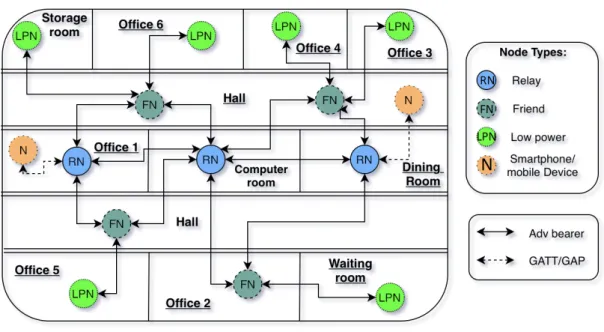
A ”relay” node is mainly dependent on being connected to a power source in order to receive and retransmit messages further to all nodes within its vicinity. Some products are designed to be run of battery for several years and are therefore not suitable to be configured as a ”relay” node. To this end Bluetooth introduced the more suitable low power alternative. A ”low power” node relies on the ”friendly” node to store its incoming messages in order to reduce radio-on time and thereby reduce power consumption. ”Proxy” nodes are used for communicating between the GATT bearer and the advertisement bearer, or in other words enable a mobile phone that does not support the Bluetooth Mesh stack to communicate with a node within
a Bluetooth Mesh network. This is achieved by letting the device communicate through the BLE GATT layer, used when communicating as an ordinary one to one connection [15].
A possible representation of a Bluetooth Mesh setup is illustrated in figure 1, where Smart phones communicate with the Low Power Node (LPN), by sending messages to the Relay Nodes (RN). The Relay Nodes then forward the messages to the Friend Nodes (FN) that in turn forwards the messages to the Low Power Nodes associated with them.
Figure 1: Representation of a Mesh network within a office building
2.2.1 Constructing a Mesh network
The Bluetooth Mesh network rely on high standards when it comes to security and privacy in the network, preventing any device from joining by just arriving for the first time to an environment which utilizes a Bluetooth Mesh network. An unprovi-sioned node does not have the possibility of communicating in a Mesh network until it becomes provisioned. One or many devices within the network may possess the role Provisioner. A provisioner device has the mandate to include or exclude devices to and from the the Mesh network. There is a certain procedure to go through in order to be a part of the network.
The first step starts with the device, known as an unprovisioned device, adver-tising its existence to the provisioner, whereby the provisioner invites the device to authenticate itself. During the authentication the device sends its properties e.g. number of nodes supported by the device, security algorithm, communication type and the public key. After the whole process of exchanging public keys and authen-ticating, the unprovisioned device is considered part of the network and referred to as a node [16]. A device has the ability to join more than one Mesh network, since whenever a device joins a network, the node gets allocated with an internal unique id and also stores the Mesh network address in order to avoid future authentications
when leaving and coming back [17].
2.2.2 Communication in a Mesh network
The communication in a Bluetooth Mesh network requires that the node is provi-sioned in the Mesh network before publishing messages. Upon provisioning, each node is assigned an unique unicast address, used for communicating directly to a specific node. Also, each node gets a group address, referring to which group the node is subscribed to. The communication in a Bluetooth Mesh network is ”message oriented”, meaning that there are multiple definitions of a message representing an unique opcode. For instance, a message representing a ”light on” message may de-fine a light set opcode, in order to tell the devices receiving the message to handle the light set request.
In a Mesh network each of the nodes representing the network, are defined and implemented according to one or multiple models. The model defines the behavior of a node, i.e. what functionality the node has. There are three definitions of models:
• ”Server” • ”Client” • ”Controller”
The server model defines the different states, state bindings, state transitions and the type of message that can be sent. The client model defines the messages that can be sent and received, as the client is not intended to have any states. The controller model contains one or multiple client and a server model(s), which lets the controller communicate with both clients and servers. The controller is mainly used for handling the control logic for rules and behaviours, e.g. a client measuring CO2, when reaching a certain threshold, the server switches on the ventilation. A
representation of a client/server context can be seen in figure 2.
Figure 2: Representation of a client/server communication
Publishing a message in a Mesh network can be done either reliable or unreliable. The reliable publish ensures that the message will arrive to the receiver. It can be
sent a specified number of times to increase the probability of successful delivery. In addition, the receiver of the message is required to reply with an acknowledgement. On the contrary, the unreliable publish does not ensure that the message will arrive, meaning that the message is sent, but nothing indicates if it is being received, as there is no acknowledgment sent back. The difference between these two lies in the latency, as the reliable mode requires more time to send and wait for an acknowledgement [18].
2.3
Bluetooth Long-range
With Bluetooth 4 there was only one version of the physical layer (PHY) of the Bluetooth stack, called LE 1M. LE 1M has the transfer symbol rate of 1 Mega sym-bols per second or Mega Baud (MBd). With Bluetooth 5 two new variants of the physical layer were added to the Bluetooth specification, LE 2M and LE Coded. The LE 2M version doubles the throughput of the transmission to 2 MBd. The LE Coded setting potentially quadruples the transmission range.
The range in this context is the maximum distance possible where data is correctly extracted from the received signal, or at least correctly enough. This limit, that defines how much of the transmitted data that is allowed to be faulty, the bit error rate (BER), is for Bluetooth set to 0.1 % max [19]. The advertised range for Blue-tooth Low energy lies between 10m to up around 100m [20]. In order to increase this range, the first thing to do would be to increase the transmission power used. This would however not be desirable as one of the key features of the standard is low energy consumption.
Another way to increase range lies within the physical layer of the Bluetooth pro-tocol stack and more precisely, the method handling erroneous transmitted packages. The way Bluetooth acts on these erroneous packages is simply by error detection using cyclic redundancy check (CRC). If an error is found, the receiver simply refrain from acknowledging the package and the sender retransmits.
The new feature in Bluetooth 5, that makes extended range possible, is error correction [4]. Some of the erroneous packages can, with the help of Forward Error Correction (FEC), be put together on the receiving end of the communication and thus packages can be decoded on a greater distance than before, with the same BER. On a sending device, the FEC encoder produces two bits of output for every one bit of input. The message size is hence doubled. After the message has been encoded it is sent to a pattern mapper. The mapper has two options, s=2 and s=8. With the s=2 setting, the mapper does no change to the input, i.e. every bit of input from the FEC encoder is the same after the pattern mapper. With the s=8 setting however, each input bit from the FEC encoder is represented with four bits of output according to table 1
Input (from FEC Encoder) Output from pattern mapper S=2 Output with S=8
0 0 0011
1 1 1100
Table 1: Example bit representation with the two coding schemes S=2 & S=8 for every bit input from the FEC encoder to the pattern mapper [4]
A message sent with s=2 is hence doubled in size compared to the original message, and s=8 results in a message that is eight times the size of the original. Application context decides which coding scheme to choose, S=2 results in range approximately doubled, whilst S=8 gives approximately four times the advertised range for LE1M. The downside is more symbols need to be transmitted which means lower data rate, 500kbit/s and 125kbit/s respectively.
2.4
Nordic nRF52
Nordic nRF52 is a series of several development kits using the BLE system on chip (SoC). The nRF52 development kits utilizes the ARM Cortex-M4F CPU, a processor featuring an ultra high performance, low power consumption and automatic power optimization in order to provide the battery efficient properties [21].
3
Related Work
This chapter present papers that relate to this thesis. They consist of evaluations of mesh networks, throughput comparisons on Bluetooth and other work with Blue-tooth where parameters and insights are useful for this thesis work. Relevance to this thesis for each paper is also explained.
3.1
Bluetooth 5.0 Throughput Comparison for
Internet of Thing Usability A Survey
Yaakop et al. [22] developed two prototypes in order to study the difference between Bluetooth 5.0 and 4.2, with the aim of experimenting with the throughput in Blue-tooth 5. The authors outline that BlueBlue-tooth 5 is able to achieve double throughput, 2 Mbps, than what was possible before with 4.2. Moreover, the authors continue with the range which also has increased and in the right circumstances could achieve up to 200m, but this would require a decrease in bandwidth in order to be able to send on greater distances, while keeping the same power requirements. In order to verify this case, the authors conducted experiments comparing the two Bluetooth versions. The setup used for the experiment was chosen to be a nRF52840 in order to test the throughput. The reason for choosing this particular development board was that it supports both Bluetooth 5.0 and 4.2 in this particular board. Furthermore, the nRF52840 also supported Arduino Uno Revision 3 standard, which was necessary in order to power the board by battery power and use a serial protocol. The ARM Cordio software was chosen to be developed on the nRF52840 board, providing the functionality when testing throughput, sending and receiving data in both directions, from/to central device. Arm Cardio is a useful software used when developing applications for the IoT, making it easier to test and analyze an application.
A home environment was chosen to test the developed prototype. Five locations in the home were chosen, looking at the attenuation with and without walls. The test consisted of the following five steps:
1. Setting up the ARM Cardio software 2. Connect the central and peripheral
3. Place the peripheral on one of the positions 4. Collect throughput data from both devices
5. Move peripheral to next position and run step 4 again
The results showed that Bluetooth 5.0 had more than double the throughput, compared to Bluetooth 4.2, when there was no wall between the central and pe-ripheral. Bluetooth 5 had an average of 1549 kbps compared to the 770 kbps of Bluetooth 4.2. In addition, findings pointed out that when having 3 walls between the devices, Bluetooth 5 achieved a throughput of 900 kbps while Bluetooth 4.2 achieved a throughput of 629 kbps. Another essential finding was that 5-6% of the throughput was decreased when there was a concrete wall obstacle.
Comments
This paper gives valuable information for this thesis by providing information about various environmental impacts on the device. Moreover, this paper confirms that the implementation of Bluetooth 5 is possible and has improved in comparison to older Bluetooth version.
3.2
Energy-Efficient Indoor Localization of
Smart Hand-Held Devices Using Bluetooth
Gu et al. [23] developed and evaluated a prototype for exploring the characteristics of Bluetooth, with the aim to localize devices under a larger area. The authors accentuate that the majority of solutions provided for indoor positioning are so called fingerprint-based localization where preset coordinates are stored in a database and the new calculated coordinates are then compared with the database in order to present the position of the device. This approach however is not optimized for dynamic localization using a mobile phone. The authors solution to a dynamic positioning problem is building a model that finds the relationship between RSSI and device position, taking into account both orientation of device as well as obstacles, time of the day and distance. Furthermore, the authors stated that the experiments they made showed to be energy consumption and time efficient.
The following 4 procedures are discussed in the paper:
• Conducting an empirical study for understanding real world impacts on the Bluetooth, e.g. distance, obstacles, signal and orientation
• Building the model for localization, defining the relationship between RSSI and target
• Proposing the Motion-assisted Device Tracking Algorithm (MADT), used for fast tracking mobile devices in a space
• Prototyping the system which was evaluated under different circumstances The authors choose 2 different locations to perform the experiments, a conference room (7.2 m x 8 m) and an exhibition hall (10 m x 14 m) both containing furniture. Experiments were conducted using different parameters focusing on time of the day, samples per second, distance, orientation and obstacles for finding the correlation between RSSI and distance. At this stage it became apparent that covering the mobile device with a book, the signal strength would be attenuated, causing the distance measurements to be inaccurate and inconsistent. In the stage of imple-menting the MADT algorithm for testing the prototype, it turned out that locating in an area smaller than 50 m2, manual searching would cost almost the same time
as the MADT algorithm, since the operation takes O(log4D) steps, where D is the
area of the room . The results shows that the localization took around 153 s in the conference room while in exhibition took 194 s. While the accuracy appeared that the error was 0.38 m in the conference room respectively 0.54 m in the exhibition, since the exhibition was larger than the conference room.
Comments
This paper gives valuable information for this thesis by providing information about various environmental impacts when using Bluetooth.
3.3
Evaluating the communication performance of an
ad hoc wireless network using Mesh Connectivity Layer
(MCL) protocol
The objective of the paper by Mansor et al. [24], is to investigate the performance of a network that utilizes the Mesh Connectivity Layer (MCL) protocol provided by Microsoft. In order to do this the authors wanted to examine the effect of hop counts, varying packet size and packet loss by pinging from a source to a destination address. The following subjects are investigated on the mesh network:
• End To End Delay : The time measured for sending a packet from source to destination node. The authors use the round trip time divided by two, for different packet size and different number of intermediate nodes
• Network Throughput: A ping utility was used to send 100 ping messages through the network in order to measure throughput on the network. Packet size and route length was varied and its impact analyzed
• Packet Loss performance: Sending 100 ping messages, the number of packets reaching its destination was counted and the impact of intermediate hops was analyzed
• File Transfer Performance (FTP): The size of a packet is increased a number of times and sent through the network to measure the impact of pay-load size and number of hops on throughput performance.
The results that the authors achieved showed that it was possible to perform a multihop within the network. From the results the authors pointed out that packet loss was effected significantly by the route length of the network while the FTP was effected on the file size and routing length.
Comments
This paper is relevant to this thesis by providing insight and ideas on what parame-ters to measure and and how to measure when evaluating mesh network performance.
4
Method
This section describes the research methodologies used to answer the research ques-tions described in section 1.1. Since the work flow consisted of three different paths, constructing the prototypes, performing experiments on the prototypes and com-paring technologies, one research method would not cover the research questions. To answer RQ1 the selected method is a comparative study, providing the structure for comparing the different technologies.
In order to provide answers to RQ2, two prototypes were developed and exper-imented upon, to provide use case recommendations. The prototypes were devel-oped following an iterative system development method. To this end, Nunamaker’s & Chen’s methodology was chosen due to its systematical development approach suitable for building a prototype [25].
Moreover, an experimenting method was chosen, in order to perform experiments on the developed prototypes. The method explained by Basili et. al. [26] was chosen due to its ease of use with clearly defined steps that provide a framework on how to perform the experiments and what to include in each step. The work flow for building the prototypes and performing the experiments is illustrated in figure 3. To ease reading and understanding, each method used is explained on its own in full below, starting with the experimentation method.
Figure 3: Representation of Nunamaker’s & Chen’s work flow on the right [25] and Experimentation work flow on the left
4.1
Experimentation
In order to perform experiments on the two built prototypes, mentioned in the next section, an experimental method was chosen providing an organized structure for performing experiments. The main steps of the methodology can be illustrated as a four step process described in the paper by Basili et al. [26].
4.1.1 Definition
This step involves stating the motivation and purpose of the experiment. By stating the motivation and purpose, the research questions was derived. The purpose and motivation of this thesis are both described in section 1.1.
4.1.2 Planning
In this stage a planning of the experiment was performed, meaning defining the criteria, what should be measured and how the experiment should be performed. This was done in order to provide a structured experimental process, planning the environments that was to be experimented in and which parameters to measure based on the criteria. The criteria for the two prototypes was derived through meetings with Anima. The planning process can be seen in section 5.1.
4.1.3 Operation
The operation step comprises the preparation, execution and analyses of the exper-iment. Here the tests, on the prototypes built, are executed in order to provide results which then are collected and compiled to graphs and tables in order to get an overview of the experiment results. The operation process can be seen in section 5.6.
4.1.4 Interpretation
The interpretation step consists of analyzing the results, which already were put together in the previous step. Here the discovered properties of each prototype are used to form and recommend use cases for each of the two prototypes. The interpretation stage of this thesis is presented in section 5.7.
4.2
Prototype development using Nunamker & Chen’s method
4.2.1 Constructing a conceptual framework
This stage consists of two parts. The first part, was defining the problem by breaking down the problem domain into research questions. This was already done in the definition stage of the experiment methodology and is presented in section 1.1. Part two consisted of a literature study, with focus on Bluetooth Mesh and Bluetooth 5, that was performed to gain general knowledge about the problem domain but also to provide the theoretical background presented in chapter 2. Furthermore, functional requirements were defined to fulfill the experiment criteria which are detailed in the
planning stage of the experiment method (see 5.1). Requirements were also added to ease the process of testing the prototypes. The resulting functional requirements are listed in 5.2.1.
4.2.2 Develop a prototype architecture
In this stage an architecture was developed for each of the two prototypes. The development boards to be used for each of the prototype were chosen based on the functional requirements previously defined. The choice of development boards was also constrained by the thesis limitations stated in section 1.2. What functionality each board should posses was decided based on the properties of the different board models. The resulting architecture is presented in section 5.3.
4.2.3 Analyze and design the system
A systematic approach was used for the prototypes software design phase and a set of UML sequence diagrams for the prototypes was produced. This was done in order to ease both the overview and implementation of the two prototypes. The result of this is illustrated in section 5.3.
4.2.4 Building the prototype
The prototypes were developed following an agile work flow in order to avoid falling behind in the development process. Each functional requirement, presented in sec-tion 5.2.1, was analyzed, implemented and tested iteratively in order to successfully satisfy the requirements defined in the planning phase 5.1 of the experiment method. 4.2.5 Observe and evaluate the prototype
The final step within the development methodology is to test and evaluate the prototypes to make sure that they perform as intended. With each iteration of the development process followed testing and evaluation with regard to the relevant requirements using suiting test cases. The final evaluation of the prototypes with relevant test cases are presented in section 5.6.
4.3
Comparative study
A comparative study was adopted in order to theoretically outline the differences of the three different technologies, mentioned in RQ1, by looking into their respective properties. The structure for this method followed a work flow suggested in an article by Lee et al. [27]. The first step in the article, was to select which mesh protocols to compare. The protocol selection was a result of meetings held with Alex Rodzevski at Anima. The protocols compared are Bluetooth Mesh, ZigBee Mesh and Z-wave. The next step was to conduct a literature survey looking into each one of the protocols compared.
Furthermore, a comparison was conducted in order to compare the restrictions the technologies have, but also how they differ in different use cases. Lastly, an eval-uation took place that summarized the results from the observations made during the comparison of the technologies.
4.3.1 Comparing Mesh protocols
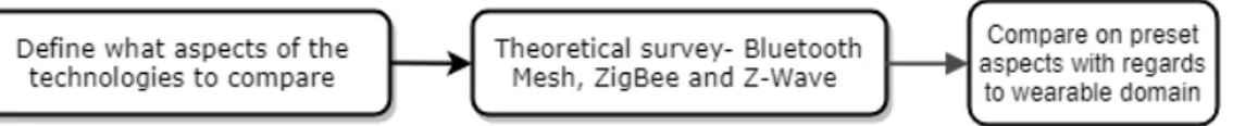
The procedure for comparing the technologies, required in the first stage to decide on which protocols to compare and also on which aspects of the protocols to compare. The next step was to collect information about the aspects selected on each of the protocols. The results of the first two steps are presented in section 5.9. Further-more, a comprehensive evaluation could take place to compare the advantages and disadvantages of each technology with regards to the the context of IoT wearables. An overview of the method used for comparing the protocols is presented in figure 4.
Figure 4: Comparative study overview
4.3.2 Evaluation
The last stage of the comparative study was to summarize the differences, with regards to the preset comparison points, for each of the mesh technologies in order to outline in what way Bluetooth Mesh could be a preferable solution and thereby answer RQ1. The comparison analyses is presented in section 5.9.4.
5
Results & Analysis
This section presents the results achieved during the thesis work. The result consist of two different phases.
The first phase consisted of planning the experiment and constructing the pro-totypes in order to perform the experiment, pointing out potential similarities and differences between the two technologies, Bluetooth Mesh and Bluetooth 5 Long Range. Later on, use cases could be derived for each of the two different Bluetooth technologies, based on the experiment results.
The second phase consisted of a theoretical comparison between Bluetooth mesh, ZigBee and Z-Wave.
5.1
Experiment planning
In order to plan for the experiment, a meeting with Alex at Anima was necessary, discussing the possible criteria and environments that could be used for their pur-pose. The meeting resulted in two environments to perform the experiment, an office and an urban area. The office environment potentially provides high signal interference by WiFi and Bluetooth used by Anima together with walls that can either reflect or absorb the signal. The urban area is a mix of open field and narrow alleys and different building materials but with low signal interference. This would provide insight on how the two environments differentiates regarding extended con-nectivity. The two also represent common every day user environments for wearable IoT devices.
5.1.1 Criteria selection
Four criteria were chosen from an IoT wearable context and are considered to be important factors that inflicts the choice of use-cases that later on would be de-rived from the experiment results. The four criteria chosen to be tested during this experiment are as follows:
1. Power consumption (Bluetooth Long-range only) - Wearable IoT de-vices are often power constraint and run on batteries. It is therefore important to know the power consumption of the technology before recommending a use case. Could it be run on batteries for an extended period of time, should it only be used occasionally or can it not be used at all for battery constrained devices?
2. Distance - From a wearable IoT context this part is an important aspect when it comes to the coverage of the device. Therefore, this is an important aspect to test in order to get a relative overview of the distance for both Bluetooth techniques.
3. Throughput - The throughput is an essential point when it comes to the IoT wearable domain. IoT wearable devices require often a moderate throughput in order to have a relative high responsiveness between the devices.
4. Hop latency (Bluetooth Mesh only) - A mesh network can potentially expand over a large physical area, thanks to relaying. It is useful to know what impact the number of intermediate nodes has on latency, when recommending a use case. How does distance between two devices within a network impact communication responsiveness?
The only type of nodes that is, at the time of writing, implemented by Nordic Semiconductor is the relay node and the proxy node. Both of these node types, are by default assigned with relaying messages within the Bluetooth Mesh network. To do this, they have to be constantly listening for messages to relay within the network and will therefore consume more energy than what is feasible for a battery constrained wearable IoT device, according to the Bluetooth Mesh profile [17].
Since this thesis investigation is aimed at battery constrained IoT wearables, current measurements for the Bluetooth Mesh nodes implemented by Nordic are not considered necessary.
The low power node, specified in the Bluetooth Mesh profile, that is designed to run on coin cell batteries, will according to Nordic be implemented in the near future.
The Long Range feature is a setting that is available for all Bluetooth 5 enabled devices including IoT wearables which is why current consumption is an aspect of interest.
The experiments on distance throughput and hop latency were performed as described below:
• Office Experiment:
– Mesh - When enough relay nodes have been placed to cover the whole office, what throughput can be obtained throughout the office?
– Long Range - Can the Long Range prototype obtain a stable connection throughout the office? What throughput is obtained within the office environment?
• Urban Experiment:
– Mesh - All available nodes provided by Anima will be placed along a path within an urban area in Malm¨o. Source node is placed in one end of the path and move a destination node along the path. What impact do intermediate number of relay nodes have on latency?
– Long Range - Central device will be placed at the same place that the source node in the Mesh test was placed. Move peripheral device along the same path used by the mesh network, until disconnect event occurs, and measure throughput at max distance, for both LE 1M and LE Coded
5.2
Prototype requirements
A list with requirements was defined based on the criteria presented in section 5.1, in order to evaluate the functionalities of Bluetooth Mesh & Long-range. As this is an exploratory thesis, the requirements are mere functional requirements that the prototypes should fulfill.
5.2.1 Requirement specifications
During the system architecture development process, functional requirements were set up for the prototypes, in order to answer research question 2, in section 1.1. Bluetooth Mesh functional requirements
BM1. The provisioner should be able to add new nodes to the Mesh network dynam-ically
BM2. The client should be able to inquire health status from all the nodes, telling the status of the nodes within the Mesh network, if present or not within the network
BM3. The client node should be able to send data to a predetermined server node, and also measure the throughput.
BM4. A node in the system should be able to recover in the Mesh network after being down
BM5. Prototype hardware must be compatible with the Mesh profile
BM6. The provisioner should not provision an already existing node with another associated address
BM7. All nodes in the system should be able to relay packets sent in the Mesh network
BM8. Any node should have the possibilities to dynamically move to another position within the Mesh network
Bluetooth Long-range functional requirements
BLR1. The Central device should be able to send bursts of data packets
BLR2. The Central device should, during run-time, be able to change the physical layer (PHY) setting, between LE Coded and LE 1M, on the connection be-tween the central and peripheral device
BLR3. Prototype hardware must be compatible with Long-range functionality BLR4. Both devices should be able to change transmission power during run-time
5.3
Prototype architecture and design
The technologies are inherently different on the architectural level, Bluetooth Long Range is a feature introduced with Bluetooth 5 that acts on the physical layer of the Bluetooth stack alone whilst Bluetooth Mesh is a profile that can be implemented on both Bluetooth 5 and 4.2.
5.3.1 Selection of development board
The selection of development board was based on the performed literature study, providing information on capable devices which can be used for building the pro-totypes. The choice of boards was limited by the stated limitations in section 1.2. The following development boards were chosen for the two different prototypes:
• Bluetooth Long-range: nRF52840
• Bluetooth Mesh: nRF52840 and nRF51422 usb dongle
Since nRF52840 is at the time of writing, the only product from Nordic that supports Bluetooth 5 and consequently the Long-Range functionality, it was chosen for the Long-Range prototype. For the Mesh prototype, the nRF51422 usb dongles has limited interaction possibilities, consisting of one on-board LED and a reset button. For this reason it was implemented as server with the main purpose of relaying messages. The nRF52840 board has three additional LEDs and four buttons making it more suitable for more advanced tasks such as provisioner and client which both require user interaction at some point, further described below.
5.3.2 Bluetooth Long-range prototype
The Long-Range prototype is a standard BLE connection between two devices, in this case two nRF52840 development kits with Bluetooth 5 support were chosen. With a changed PHY setting of handling packet error correction, this increases the probability that the packets will successfully be delivered to the receiving device, thereby extending the possible range between the two devices. The prototype should simulate a normal setup between a cellphone and a watch, thus one device acts as a central and the other as a peripheral device. The total size of the sent packet burst for this prototype is set to 256KB, providing a good average on the measured throughput, as well as keeping the time taken to perform the test reasonable. The central device handles all user interaction which in this case is functionality for testing the application:
• Changing physical setting: By pressing a button on the central board a local request for changing the physical setting (PHY) is invoked, changing either to LE Coded or LE 1M. This triggers a request on the peripheral device which automatically updates itself to the new setting and responds with a success or fail code. If the central device receives a success code the physical setting is now in use, else it reverts back to the old setting.
• Throughput: By pressing a second button on the central board, a burst of 256 fixed size data packages is sent to the peripheral and time for every successful transmission is measured. This gives an indication of how distance and the above mentioned parameters, PHY setting and environmental, inflict on the general link performance.
5.3.3 Bluetooth Long-range prototype design
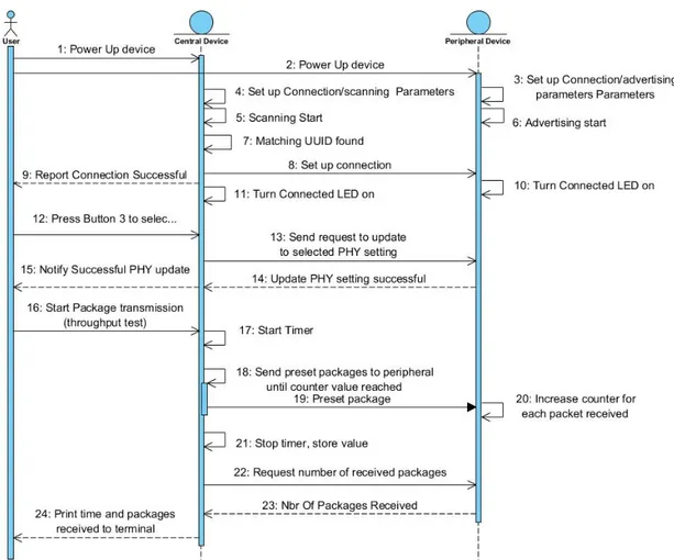
A sequence diagram was made in order to give an overview of the process when con-necting and sending with the Bluetooth Long-range prototype. This was necessary in order to provide an overview of how the devices interact between each other. The sequence diagram is illustrated in figure 5. The diagram describes the steps required for the experiment, when using Bluetooth Mesh prototype.
Figure 5: Sequence Diagram For Long-Range Prototype
5.3.4 Bluetooth Mesh prototype
The Bluetooth Mesh prototype consists of seven devices. Four nRF52840 develop-ment kits and three nRF51422 USB dongles, provided by Anima. All devices possess relay capabilities. The size of the message packet sent, for testing throughput and network delay, was chosen to 15 byte as this is the maximum size of a packet without segmentation. The functionality implemented on the various boards are described below.
• Provisioner: One of the nRF52840 development kits are implemented as a provisioner taking care of provisioning and configuration of new devices to the network and network setup. It also later on acts as a relay node, forwarding messages within the network when possible.
• Server: The second and third nRF52840 development card and the three nRF51422 USB dongles are implemented as servers in the mesh network. A server’s main functionality is simply to react upon requests from the client node e.g. to switch their on-board LED on or off.
One of the nRF52840 boards and the three nRF51422s usb dongles main pur-pose for this prototype is relaying messages within the network, thus increase network size both in numbers and in span.
The other nRF52840 additionally has an extended message function that was used for testing throughput within the mesh network. It simply receives a message with a 15 byte payload from the client and responds with a 1 byte acknowledgement.
• Client: The fourth nRF52840 board is implemented as a client that can com-municate commands to the four server devices. The push of a button triggers an event that sends out an OPCODE-message that tells the receiving servers what to do, in this case toggle an on-board LED. The first button triggers the server that was first provisioned, in our case the nRF52840 server board, and button number two and three triggers servers with even and odd network ad-dresses respectively. The fourth button starts an event that sends 10 packages with a 15 byte payload size each, timing each package from transmission from client to the receiving of the response from the server.
Additionally each server was set to periodically send so called health-messages to the client. The health message contains information of the servers current status within the network, i.e. fault status and RSSI-value measured between the server and its closest node. For this prototype the health message period is set to one message per second for each node which is unnecessarily high, but could help simulate traffic within a Mesh network and provide a clear indication of which nodes are still within network range.
5.3.5 Bluetooth Mesh design
In order to analyze the system a sequence diagram was made illustrating each part of the system on how different devices interact. The whole process is illustrated in figure 6. The diagram describes the steps required for the experiment, when using the Bluetooth Mesh prototype.
Figure 6: Sequence Diagram For Mesh Prototype
5.4
Building the prototype
This section describes the process of building the prototypes, the prerequisites in order to get started with the development of the prototype. In an early stage it was decided that two prototypes would be built, one representing the Bluetooth Mesh and one Bluetooth Long-range. Every step on the way was tested with the test cases in appendix B.
5.4.1 Bluetooth Long-range prototype
The first step was to setup the development environment and the Nordic nRF5 SDK according to the instructions in appendix A.1. Next step was getting the peripheral and the central device implemented and to make them start advertising and scanning.
Nordic offer a lot of example code and an active community [28] to help cos-tumers, novice to experienced, with development on their products. Once a con-nection was established between the two units, other features could be implemented such as button events, data package transmission and the changing of the PHY setting.
5.4.2 Bluetooth Mesh prototype
The first step in the mesh prototype development was installing the necessary de-pendencies by following the steps in appendix A.2. The next step was to get basic communication between two or more nodes. Also this time the community and examples provided by Nordic were helpful.
One provisioner, one client and a server were necessary to get the basic imple-mentation of turning a light on or off working. The provisioner starts with scanning for a device with a pre-set client ID. When found, the client is provisioned and configured, and then the provisioner starts to search for nearby server nodes. When found, the same procedure of provisioning and configuring takes place.
Next step was expanding the models used to send custom messages through the mesh network that so far only consisted of three devices. This required a more thorough understanding of how the Mesh network is operating. At a glance of the examples, everything seems to be happening through callbacks, and it is difficult to see where things are triggered which makes it more difficult to reproduce behavior based on examples alone. Theoretical understanding and testing was necessary.
The last step was introducing more servers on the network. This step went quick since the provisioner was set to accept all nodes with the same server ID and the provisioning is the same process as with the first server.
5.5
Observe and evaluate the prototype
In order to verify that the two developed prototypes fulfill the functional require-ments presented in section 5.2.1, testing was necessary. This was done by executing the test cases, shown in appendix B, on each function iteratively verifying that the prototype works as intended. During each test the prototype was observed in order to see if anything was missing or not functioning as intended.
5.6
Operation
Testing the prototypes in real world environments was necessary to make a fair assessment, identifying strengths and weaknesses for each prototype in order to find relevant use cases based on the results achieved on the prototypes.
This section describes the operation phase of the experiment methodology. Ex-periments for each prototype within the two environments mentioned are explained one by one. Data collected in each experiment is then presented in section 5.7.
5.6.1 Bluetooth Mesh urban area experiment
In order to start with the experiment, it was first necessary to place the nodes. As previously stated during the prototype architecture 5.3, a total of 7 nodes were placed on different positions. Two of the nodes, one client and one server, was spec-ified to send messages to each other in order to perform the experiment, measuring the hop latency. Before placing all of the nodes, the provisioning of the nodes was necessary. This was done by first starting the provisioner, client and one of the servers. By doing this the client could specify to which server it should be sending the messages, as the intention is to send to only one server. When the client and server were provisioned, the rest of the devices could be provisioned.
Figure 7: Mesh network setup in an urban area, Malm¨o
The client was placed first at the Client point, as seen in figure 7, while all servers were powered off. Then, one server at a time was powered on, and brought as far away as possible from the previous node as illustrated in the figure represented as numbers 1-5. The server node with the extended message functionality was placed as the last node at the Server point, as seen in the figure.
Max distance between each node was indicated by the sent health messages that let the client know if the server is within network reach or not. The reason for placing the nodes far away from each other was in order to control the number of hops by placing the nodes on a relative straight line, maximizing the distance.
After the nodes were placed, the experiment could begin. Ten packets with 15 bytes of payload each were sent from client to server, in order to measure the latency. Since each packet takes different amount of time to arrive to the server, depending on the hop count, it was decided that the packet needed to be sent 10 times. This in order to get an average time on the number of hops. Confirming that the message arrived to the server node, a short acknowledge message was sent back to indicate that the message had arrived.
In order to measure the latency for each hop count, the ”Server” node was successively moved from position to position, starting from the last position ”Server” and moving towards node 1 as seen in the figure. Moving the ”Server” node would
also provide an indication on the dynamic movement in the Mesh network. The result of the Mesh prototype experiment is presented in section 5.7.
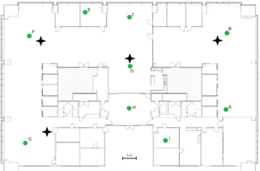
5.6.2 Bluetooth Mesh office experiment
The procedure for placing nodes in the office environment was similar to the one described in the previous section. Four relaying server nodes, excluding the client and the server receiving test messages, were enough to provide network coverage throughout the office environment. A map of the office can be seen in figure 8. Stars represent relay node placements and the nine letters are the points where the server was placed while testing. A client node was placed on position ”A”, keeping it static, and the specified server node, that should receive test data, was moved around to each of the predefined letter points. This was mainly done in order to observe the connection to the Mesh network, if the connection would ever be dropped within the Mesh network or maintain its presence. Additionally, on each of the positions, 10, 15 bytes messages were sent in order to measure the throughput.
5.6.3 Bluetooth Long-range urban area experiment
The Long-range experiment was tested in the same urban area placement as the Mesh experiment, in order to reflect the differences when using Bluetooth Mesh and Long-range. The experiment consisted of first powering on both central and peripheral in order to pair the two devices. The central was placed at a static position and the peripheral was placed on three different positions, which is illustrated in figure 9.
Figure 9: Throughput comparison LE 1M & LE Coded in an urban area, Malm¨o. Maximum Distance for each setting and Line of Sight (LoS)
The three different positions represent the line of sight and the two respective furthest positions for each PHY setting, LE Coded and LE 1M. The furthest posi-tions for LE Coded and LE 1M were found by moving in the same path which was used for the Mesh experiment until a disconnection event was triggered, recording the achieved distance. With these three positions acquired, both LE Coded and LE 1M were tested in line of sight and their respective furthest positions. This was done by sending packets with a total size of 256 KB, from the central to the peripheral. The result of the Long-range prototype experiment is presented in section 5.7. 5.6.4 Bluetooth Long-range office experiment
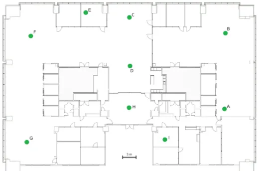
The experiment performed in the office environment consisted of two main steps. The first step was to pair the two devices, central and peripheral. This was done by turning on both, waiting for the devices to bond to each other. As seen in the figure 10, the same nine letter positions were used as for the mesh office experiment in order to test the connectivity within the office. Furthermore, the test was performed two times for each PHY setting, LE 1M and LE Coded, in order to get a fair average result. The reason for these two PHY was to see differences when using Long-range and the ordinary 1 Mbps connection.
Figure 10: Test positions for Long Range prototype office experiment
To perform the experiment the central device was placed static on position ”A” and the peripheral was moved from position ”A” to ”I”, performing a test on every position. The test consisted of sending a total of 256 KB of data packets. These packets were sent in order to measure the average throughput on each of the 9 positions. Moreover, the connection was observed when moving from one position to another in order to test the coverage with the two respective PHY settings. When the first test with LE 1M was done then the next test with LE Coded could be performed, by changing the PHY setting and redo same process described earlier. 5.6.5 Long Range current measurements
To get an indication of the differences between the standard LE 1M setting and LE Coded with regards to power consumption, current measurements were made according to the Nordic Semiconductor guide on current measurements [29]. Since each package on LE Coded, with S=8, are eight times larger than the LE 1M package, the radio on time is increased during transmission and in turn power consumption is increased. Images of the measurements can be seen in appendix C and the relevant data is presented in table 4 under section 5.7.
5.7
Interpretation
In this section an interpretation of the results achieved during the experiments are discussed. First the results from the two conducted experiments, urban and office, are presented for each Bluetooth technology and then the overall results of the experiments are summarized.
5.7.1 Urban area environment
The result from the experiments in the urban environment for both Bluetooth Mesh and Long range can be seen in figures 11 and 12 respectively. The Mesh experiment shows that the number of hops used from source to destination has a significant impact on the total latency. As can be seen in figure 11 the increase in latency per hop is not linear. The reason for this is not clear but could be because of environmental factors in the test area. Some nodes were closer to each other than others, and part of the test area was within narrow alleys where signal reflection is increased. This indicates that a mesh network can be optimized by placing nodes in a certain way, something that is, however, not within the scope of this thesis.
Figure 11: Mesh network hop latency, 15 bytes payload
The observation made of the two prototypes tested, indicate that Mesh is a lot slower than LE Coded when it comes to data transfer. Comparing the Mesh hop latency with LE Coded throughput, there is a significant difference in the data rate between the two. Mesh proved to be 278 times slower than the LE Coded central-peripheral connection with the Long-range prototype, both at their respective max distance.
As seen in figure 12, there is a clear difference between the two different PHY settings when using the Long-range prototype. LE Coded provided a longer distance with a lower throughput, while LE 1M had a lower distance with a higher through-put. Relating to the theory in ideal case, LE Coded should provide an increase of four times the distance of LE 1M. However, as seen in the figure there is only an
increase of 45%, this is mainly because of the environmental impacts, e.g. objects in the urban area blocking the signal.
Figure 12: Throughput in LoS and max distances for respective PHY setting, Long-range prototype
5.7.2 Office environment
Results collected during the conducted experiments in the office environment, showed that the Long-range prototype with LE Coded PHY setting achieved more or less the same coverage within the office as the Mesh prototype. However, when using the Long-range prototype with LE 1M PHY setting, the devices lost connection when approaching position ”G”, illustrated with red cross lines in figure 13.
Figure 13: Coverage of 1Mbps in a office environment
On the other hand, the Mesh network consisted of a total of 6 nodes in compari-son to one connection with Long-range. In this case the Long-range prototype with
LE Coded PHY setting would be a preferable solution in an office environment. Moreover, as seen in the table 2 and 3 which were assembled during the experi-mentation for respective prototype, there is once again a significant difference in the throughput between the two prototypes. The Long-range prototype with LE Coded had an average of 22 kbps, while LE 1M had an average of 179 kbps. The Mesh prototype on the other hand had an average of 315 bps confirming that the Mesh network overall has the lowest throughput.
Table 2: Bluetooth Mesh prototype throughput test in an office environment 15 byte payload
Bluetooth Mesh Throughput
Position Throughput(bps) Time(sec)
A 348 0.35 B 229 0.52 C 432 0.28 D 235 0.51 E 411 0.29 F 325 0.37 G 66 1.82 H 364 0.33 I 427 0.28
Table 3: Bluetooth Long-range prototype throughput test in an office environment sending 256 KB
PHY LE Coded (Long-range) PHY LE 1M
Position Throughput (kbps) Time(sec) Throughput (kbps) Time (sec)
A 26 79.8 236 8.7 B 24 86 182 11.6 C 22 94.2 158 13.4 D 22 95.2 171 12.3 E 22 94 177 11.9 F 22 95.5 122 17.2 G 15 141.8 n/a n/a H 19 112.4 175 12 I 24 88 209 10.3
Furthermore, through observations of the results for the respective prototypes, it could be seen that when it comes to PHY LE Coded, the throughput is stable within the office. However, both Mesh and LE 1M proved to be unstable with a lot of variation in throughput when tested around the office. The reason for the varying Mesh throughput is mainly due to the variety in hop count. For LE 1M the reason could be because of various signal reflections or interference that increased package loss, which in turn results in reduced throughput.
5.7.3 Long Range Current Measurements Results
The results of the current consumption measurements are listed in table 4. The current consumption is significantly higher for LE Coded in both idle state and when sending data. The fact that any data transmission takes approximately eight times longer for the LE Coded setting than the LE 1M setting, and thereby radio-on time is increased, should be taken into account. When sending a fixed amount of data, the heightened average current consumption will be consumed over a longer period of time.
The measurement is done with the connection interval set to 200 ms on both PHY settings, and the peripheral latency is set to 0. This means that to keep the connection, the central device synchronizes with the peripheral device every 200 ms and the peripheral device is required to respond to every request. Since the difference between the two is significant even in idle state, it is recommended to increase the connection interval parameter for the LE Coded setting, lowering the amount of connection events, with the downside of increasing the over-all response time.
Table 4: Current consumption measured in idle mode and during data transmission, LE 1M and LE Coded
Long Range Current Measurements PHY setting Average Consumption Idle
(µA)
Average Consumption Data Transmission (mA)
LE 1M 33.52 7.51
LE Coded 108 10.26
5.7.4 Summary
To summarize, Bluetooth Mesh proved to be a good technology when it comes to lightweight sending of data, e.g. small commands to turn on or off the LED. Fur-thermore, Bluetooth Mesh is a suitable way of extending the connectivity between devices over larger areas where obstacles limit connectivity. Measures show how-ever that Bluetooth Mesh is heavily constrained when it comes to latency over an increasing number of intermediate nodes. With regards to throughput, Long-range prototype using the LE Coded PHY setting, would be a preferable solution, if the intention is to send data 10-100 meters without too many obstacles. As for the Office environment, the Long-range prototype using the LE Coded PHY setting, could cover the whole office, thus proved to be an improvement compared to the LE 1M setting. This is however dependant on how many and what types of walls that exists within the office environment, and therefore the recommendation could be considered location specific.
The increase in power consumption, as result indicate from the current measure-ments presented in table 4, needs to be taken into account, as the larger size data package increases radio-on time and thus increases power consumption. Careful tweaking of connection parameters might be of value if it is to be used by low power peripheral devices for an extended amount of time.
5.8
Prototype use cases
In order to recommend suitable use cases for each of the two technologies, multiple methods were used:
1. The first step was to define general use case areas, e.g. streaming or sensor data communication, for Bluetooth through brainstorming.
2. The second step was to introduce a set of possible use cases within each area, that relates to the device domain e.g. small battery constraint devices. This was done by using a modified version of the 365 brainwriting method discussed by Pahl et al. [30], where use cases for each area emerged iteratively. Areas and use cases are presented in appendix D.
3. The third step was to filter the list of use cases based on the results achieved during the experiments, from previous section 5.7. This was done by assessing the use case if applicable or not, as seen in table 8 in appendix D. This in turn further shortened the list of possible use case choices.
4. The final step consisted of selecting the most suitable use cases from the filtered list. Since Anima is mainly operating in the wearable and mobile IoT domain, use cases with a more static network setup were removed. The use cases chosen to be recommended for each Bluetooth technology are presented below. 5.8.1 Bluetooth Mesh use cases
• Child care/Retirement home - This use case is a suitable choice for Blue-tooth Mesh. Relay nodes could be placed in light fixtures and light switches to provide coverage throughout the facility. Letting the elderly/children wear wristbands, would provide the staff with information if elderly/children are still within reach. Moreover, the staff members at the day care could get statistics of the total daily movement from the children. As for the elderly, at an ele-vated heart rate, or other out of the ordinary events, the wristband could use its last calculated position and alert the staff members with a message through the Mesh network.
• Greenhouse monitoring system - Plant specific monitors, measuring hu-midity and temperature, could operate for a long time on batteries. They could communicate with sprinkler and ventilation systems. User could manu-ally control and configure systems or sections of the greenhouse with an app using smart phone as a Bluetooth controller. Plants could be moved around without the need to reprogram the systems and the greenhouse facility could easily expand adding more and more nodes when necessary.
• Animal Tracker (Agriculture) - A farmer could mount relay nodes around the pastures and supply the livestock with battery powered tags. This way he/she could keep track of each individual animal of the herd.

![Figure 3: Representation of Nunamaker’s & Chen’s work flow on the right [25] and Experimentation work flow on the left](https://thumb-eu.123doks.com/thumbv2/5dokorg/4056258.83823/18.892.287.603.604.961/figure-representation-nunamaker-chen-work-flow-right-experimentation.webp)