Mälardalen University Press Licentiate Theses No. 161
MODE SWITCH FOR COMPONENT-BASED MULTI-MODE SYSTEMS
Hang Yin
2012
School of Innovation, Design and Engineering Mälardalen University Press Licentiate Theses
No. 161
MODE SWITCH FOR COMPONENT-BASED MULTI-MODE SYSTEMS
Hang Yin
2012
Abstract
Component-based software engineering is becoming a prominent solution to the development of complex embedded systems. Since it allows a system to be built by reusable and independently developed components, component-based development substantially facilitates the development of a complex embedded system and allows its complexity to be better managed. Meanwhile, parti-tioning system behavior into multiple operational modes is also an effective approach to reducing system complexity. Combining the component-based ap-proach with the multi-mode apap-proach, we get a component-based multi-mode system, for which a key issue is its mode switch handling. The mode switch of such a system corresponds to the joint mode switches of many hierarchi-cally organized components. Such a mode switch is not trivial as it amounts to the mode switch coordination of different components that are independently developed.
Since most existing approaches to mode switch handling assume that mode switch is a global event of the entire system, they cannot be easily applied to component-based multi-mode systems where both the mode switch of the system and each individual component must be considered, and where compo-nents cannot be assumed to have global knowledge of the system. In this thesis, we present a mechanism—the Mode Switch Logic (MSL)—which provides an effective solution to mode switch in component-based multi-mode systems. MSL enables a multi-mode system to be developed in a component-based man-ner, including (1) a mode-aware component model proposed to suit the multi-mode context; (2) a multi-mode mapping mechanism for the seamless composition of multi-mode components and their mode switch guidance; (3) a mode switch runtime mechanism which coordinates the mode switches of all related compo-nents so that the mode switch can be correctly and efficiently performed at the system level; and (4) a timing analysis for mode switches realized by MSL. All the essential elements of MSL are additionally demonstrated by a case study.
Populärvetenskaplig
sammanfattning
Vi omges dagligen av inbyggda system; datorsystem som är inbyggda i an-dra produkter. De finns i allt från smarta telefoner, skrivare, medicinska ap-parater och industrirobotar till bilar och flygplan. På grund av den ökande efterfrågan på funktionalitet, lägre kostnader och kortare tid till marknaden, ut-gör programvaran en allt viktigare del av dessa inbyggda system. Den ökande komplexiteten i programvaran ställer i sin tur krav på nya, mer effektiva och skalbara metoder för programvaruutveckling.
En metod som introducerats för att hantera den ökande komplexiteten i gramvaran är att bygga programvarusystemen med hjälp av förutvecklade pro-gramvarukomponenter; så kallad komponentbaserad programvaru-utveckling som kan liknas vid att bygga med lego. Ett annat sätt att reducera komplex-iteten är att dela upp systemet i olika driftlägen och hantera dessa oberoende av varandra. Till exempel kan programvaran som styr ett flygplan vara uppdelad i driftlägen så som taxi, start, flyg och landning. Om man kombinerar kompo-nentbaserad utveckling med uppdelning av systemet i olika driftlägen, så får man ett komponentbaserat system med multipla driftlägen. En central uppgift för ett sådant system är att på ett effektivt och förutsägbart sätt växla mellan systemets driftlägen utifrån växling av de ingående komponenternas driftlä-gen. Befintliga metoder för växling av driftläge utgår från att växlingen är en global händelse, vilket inte är förenligt med den grundläggande principen om oberoende utvecklade komponenter som gäller för komponentbaserad utveck-ling.
I denna avhandling presenterar vi en ny metod för växling av driftläge, kallad Mode Switch Logic (MSL). MSL möjliggör driftlägesväxling på ett sätt som är förenligt med oberoende utveckling av de komponenter som ingår i
systemet . Vi har dessutom utvecklat en metod för att analysera hur lång tid det tar att genomföra driftväxling. I en fallstudie illustrerar vi tidsanalysen och de mekanismer vi utvecklat.
摘
摘
摘要
要
要
基于组件的软件工程逐渐在复杂嵌入式系统的开发中热门起来。由于它 可以用可重复利用的和独立开发的组件来构建系统,组件式开发可以很 大程度上提高复杂嵌入式系统的开发进程,并且系统的复杂性也更容易 管理。与此同时,将系统不同的功能划分为不同的操作模式也是一个降 低系统复杂度的有效办法。将基于组件的方法和多操作模式的方法结合 起来,我们就可以得到一种基于组件的多模式系统。这种系统的一个关 键问题就是对于它的不同模式转换的处理。这种系统的模式转换等同于 许多系统内部各个阶层的组件的模式转换。这种模式转换不容忽视,因 为不同组件的模式转换需要很好的相互协调。 目前大多数处理模式转换的方法都假设模式转换是整个系统的一种 全局事件,而对于基于组件的多模式系统来说,无论是系统的模式转换 还是每一个内部组件的模式转换都需要考虑,而且每个组件不允许了 解系统的全局信息,所以这些方法并不能简单的应用到基于组件的多 模式系统。本篇论文针对此类问题介绍了一种我们开发的模式转换逻 辑(MSL: Mode Switch Logic)。作为一种有效的手段来处理基于组件的多 模式系统的模式转换,MSL允许用基于组件的开发方式来开发多模式系 统,它包括(1) 一种适合多模式环境的有模式意识的组件模型; (2) 一种 模式映射机制,这种机制使得多模式的组件可以无缝叠加,并且可以引 导多模式组件的模式转换; (3) 一种实时模式转换机制,它可以协调所有 相关组件的模式转换从而保证整个系统能够正确而且高效的完成模式转 换; (4) 对以MSL实现的模式转换进行时间分析。另外,MSL的所有关键 元素都在本论文中通过一个案例被演示出来。 VIIAcknowledgements
A couple of months ago, I decided to write a monograph as my Licentiate the-sis, without knowing how challenging such an ambitious goal was. Fortunately, I managed to keep this promise after more than two months’ torment from the thesis writing. I have been through a really tough period to fulfill this task, however, I still believe that I have made the right decision. The accomplish-ment of the thesis is actually beyond my own competence and effort. Herein, I shall express my gratitude to those who I ever got help from1.
First, I would like to thank my supervisor Hans Hansson for assigning such an interesting research topic for me as well as his invaluable guidance even since I was a master student at MDH. Thanks to his enormous help and tute-lage, I became more and more capable of doing research, in terms of inves-tigating existing related works, solving hard research problems, writing good academic papers, and many other aspects. I am so impressed that he could know so many technical details of my work and even sometimes point out the hidden problems of my ideas from our discussions. It is definitely my supreme honor to be one of his PhD students! I also would like to thank my assistant supervisors Paul Pettersson and Thomas Nolte. As a UPPAAL expert, Paul has offered many helpful suggestions for solving my UPPAAL problems (hope-fully you are not bothered too much by my occasional bizarre questions on UPPAAL). Also, thank Mikael Sjödin for being the examiner of my Licentiate proposal and providing so valuable feedbacks.
Many thanks go to Damir Isovic, whose visit to my home university ECUST in 2007 became the initial and key motivation for me, who had no ambition to go abroad before, to come to MDH. Now I am so pleased to wit-ness the intimate cooperation between MDH and ECUST. Also thank him for giving me the opportunity to be exchanged to TU/e in Eindhoven in 2009. I
re-1Occasionally I may thank someone multiple times for different reasons.
ally got a hard time there (a good evidence is that I lost 5kg within five months), yet it became one of my most memorable experiences. I need to thank Damir again for recommending me to Hans for his PhD position when I was still in Eindhoven. In addition, I am grateful to my ex-supervisor in ECUST, Huifeng Wang, for her encouragement of my MDH plan. Moreover, thank Jiale Zhou and his family for their financial assistance before I came to Sweden. Jiale and I flew to Sweden together, exchanged to TU/e together, taking almost the same courses, and now we are both PhD students at MRTC. It is indeed hard to get rid of you:)
I want to express my special thanks to Jan Carlson who has aided me a lot in my research. Even though we are in different research groups, many novel ideas have popped up from our discussions and they are extremely ben-eficial for me. I sincerely appreciate Etienne Borde, who yet is not at MRTC any more, for his active help at the beginning of my PhD. Thank Björn Lisper for enlightening us about a model-checking approach which afterwards con-tributed to our ECRTS paper. Additional thanks go to Barbara Gallina and Dag Nyström, who ever inspired me to borrow some ideas from the classic two-phase commit protocol used in distributed databases for my own research. One more thing, thank Dag for his "illegal" buns in the ES meetings:) Besides, I would love to thank Cristina Seceleanu who has been so enthusiastic to help me with theorem proving (sorry that I did not do a good job and have to leave it as my future work for the time being).
Since I started my master study at MDH, I have taken numerous courses that established good foundations for my research. Coincidently, most of the lecturers and lab assistants of these courses now turn out to be my colleagues. Thank Damir Isovic and Moris Behnam for the course Real-Time Systems 1. Thank Gordana Dodig-Crnkovic and Jan Gustafsson for teaching me the re-search methodology. Thank Thomas Nolte and many others for the course Real-Time Systems 2. Thank Mikael Ekström for the course Sensor Tech-niques. Thank Lars Asplund, Fredrik Ekstrand, Jörgen Lidholm and the artist Mikael Genbergs for the robot project "Roony". We could not let Roony carry a Swedish house to the moon as required, but it was absolutely a lot of fun to be engaged in this project. Thank Paul Pettersson, Cristina Seceleanu, Hans Hansson and Leo Hatvani for the advanced software verification and validation course. Thank Thomas Nolte and Emma Nehrenheim for the PhD introduction course, which is undoubtedly my favorite PhD course that not only covers such a variety of hot and interesting topics related to research, but also has amused us in the coffee and lunch sessions:) Thank my supervisor Hans Hansson again for the research planning course. Thank Phil McMim from University of Sheffield
XI and Paul Pettersson for the search-based testing course. Thank Ivica Crnkovi´c, Séverine Sentilles and Aneta Vulgarakis for the advanced CBSE course which is rather conducive to my research. Thank Iain Bate from University of York, Sasikumar Punnekkat and Hans Hansson for the course Introduction to Safety-Critical Systems. Furthermore, my heartfelt thanks go to Reinder J. Bril, U˘gur Keskin, and other members in the System Architecture and Networking (SAN) group in TU/e for their great help during my stay in Eindhoven.
I have been to six countries in recent two years for international confer-ences, the ARTIST summer school and the last PROGRESS annual trip. I was never alone for any trip, as I always got accompanied by a few MRTC fellows who made my each single journey hilarious. First I want to convey my grati-tude to Ivica Crnkovi´c, Magnus Larsson and Jan Carlson who took care of me throughout CompArch 2012 this June. I also would like to thank Guillermo Rodriguez-Navas for being the local guide in Sóller for us in 2010 and now I am delighted to have him here at MRTC. Thank Thomas Nolte again for ac-companying me in all the real-time conferences and for being a hot topic to start a conversation with other researchers (most people mentioned your name after identifying my affiliation). In addition, many thanks go to my other con-ference/summer school fellows: Andreas Gustavsson, Farhang Nemati, Josip Maras, Luka Lednicki, Mikael Åsberg, Mohammad Ashjaei, Moris Behnam, Rafia Inam, Saad Mubeen, Sara Afshar and Yue Lu.
I would love to acknowledge all the administrative staff at IDT who have made my daily affairs a lot easier: in particular, Carola Ryttersson, Susanne Fronnå, Gunnar Widforss, Malin Rosqvist, and Åsa Lundkvist.
I admit that sometimes I concentrate too much on working at the sacrifice of missing countless coffee breaks. However, I never forget the happy moments with so many of you from PhD/Licentiate parties, ES meetings/challenges and other various exciting activities. Apart from those who I have thanked above, I give my sincere thanks to Abhilash Thekkilakattil, Adnan Causevic, Aida Cau-sevic, Andreas Ermedahl, Andreas Johnsen, Daniel Sundmark, Eduard Paul Enoiu, Federico Ciccozzi, Hüseyin Aysan, Irfan ˘Sljivo, Jagadish Suryadevara, Jukka Mäki-Turja, Juraj Feljan, Kan Yu, Kivanc Doganay, Kristina Lundqvist, Mats Björkman, Meng Liu, Nima Moghaddami Khalilzad, Ning Xiong, Radu Dobrin, Raluca Marinescu (as your roommate, I apologize for being a bit tac-iturn these months due to my thesis writing. In case you have any complaint, please blame the thesis, not me:)), Sigrid Eldh, Stefan Bygde, Svetlana Girs and many others around me. Additional thanks are reserved for some of my former colleagues who are not working at MRTC any more, including Andreas Hjertström, my ex-roommate Stefan Björnander and Johan Kraft.
Working for the ARROWS project, I have been funded by Vetenskapsrådet. I am deeply thankful for its financial support.
I give my wholehearted thanks to my parents for their immense parental love and care. Although I have been away from home for more than eleven years (seven years in Shanghai and more than four years in Sweden) and family reunion has gradually become an annual event for us, they are always encour-aging me, respecting my own decisions, and doing their best to support my life when I was still not economically independent. Also, I am so grateful to all my relatives in China. In particular, I cherish the memory of my dear grandmother who unfortunately left us just one week before I came back to China this Au-gust, desperate for seeing me in her last minute. She must be proud of me in the heaven right now.
Last but foremost, I would deliver my deepest thanks and love to my girl-friend Hongwan Qin who has brought the true jubilance in my life. Thank you for being so tolerable, considerate and supportive all the time. Nothing else could make me feel more fortunate than to have you with me! We have shared pains and joys while I am supervising your master thesis. I know that some-times I am not lenient enough. Believe me, there is always a tradeoff between a good boyfriend and a good supervisor:)
Finally, thank everyone who is patient to go through my tedious acknowl-edgements. This is the only one non-technical part of the thesis and you may realize that it is still the most interesting part after comparing it with the main body of the thesis, which could be even more boring. Due to my limitation to provide an exhaustive list of people’s names that deserve my appreciation, it is hard to ensure that I fail to mention any important people here. If this really happens, please do let me know and I will thank you twice next time in my PhD thesis:)
Thank you all!
Hang Yin Västerås, October 29, 2012
P.S. My name is 尹航 which is literally translated into Yin Hang. According to Chinese tradition, the family name Yin is placed in front. However, my name is frequently written as Hang Yin in accordance with Western tradition.
List of Publications
Papers related to the thesis:
Conference and workshop papers
• Timing analysis for mode switch in component-based multi-mode sys-tems. Yin Hang, Hans Hansson. In proceedings of 24th Euromicro
Con-ference on Real-Time Systems (ECRTS’12), pages 255-264, Pisa, Italy, July, 2012.
• Towards mode switch handling in component-based multi-mode systems.
Yin Hang, Jan Carlson, Hans Hansson. In proceedings of 15th Interna-tional ACM SIGSOFT Symposium on Component Based Software En-gineering (CBSE’12), pages 183-188, Bertinoro, Italy, June, 2012.
• A mode mapping mechanism for component-based multi-mode systems.
Yin Hang, Hans Hansson. In proceedings of 4th Workshop on Com-positional Theory and Technology for Real-Time Embedded Systems (CRTS’11), pages 38-45, Vienna, Austria, November, 2011.
• Timing analysis for a composable mode switch. Yin Hang, Hans
Hans-son. In proceedings of the 23rd Euromicro Conference on Real-Time Systems (ECRTS’11), WIP, pages 15-18, Porto, Portugal, July, 2011.
• Composable mode switch for component-based systems. Yin Hang,
Eti-enne Borde, Hans Hansson. In proceedings of 3rd Workshop on Adap-tive and Reconfigurable Embedded Systems (APRES’11), pages 19-22, Chicago, April, 2011.
Technical reports
• A UPPAAL model for timing analysis of atomic execution in component-based multi-mode systems. Yin Hang, Hans Hansson, Technical Report,
Mälardalen Real-Time Research Center (MRTC), Mälardalen Univer-sity, Sweden, February, 2012.
• A Mode Switch Logic for component-based multi-mode systems.
Yin Hang, Hans Hansson, MRTC report ISSN 1404-3041 ISRN MDH-MRTC-261/2012-1-SE, Mälardalen Real-Time Research Centre (MRTC), Mälardalen University, Sweden, January, 2012.
Papers not related to the thesis:
Conference and workshop papers
• Accelerating exact schedulability analysis for fixed-priority scheduling.
Yin Hang, Zhou Jiale, U˘gur Keskin, Reinder J. Bril. In proceedings of the 22nd Euromicro Conference on Real-Time Systems (ECRTS’10), WIP, pages 5-8, Brussels, Belgium, July, 2010.
List of Acronyms
ACC Adaptive Cruise Control, page 99 AEG Atomic Execution Group, page 61 CBD Component-Based Development, page 4 CBMMS Component-Based Multi-Mode System, page 5 CBSE Component-Based Software Engineering, page 1 DDM Dominant Default Mode, page 49
DPS Data Processing Status, page 64 EPF Extra-Functional Property, page 18 MMA Mode Mapping Automata, page 49 MSC Mode Switch Completion, page 30 MSD Mode Switch Denial, page 29
MSDM Mode Switch Decision Maker, page 28 MSDT Mode Switch Detecting Time, page 78 MSI Mode Switch Instruction, page 29 MSL Mode Switch Logic, page 8
MSP protocol Mode Switch Propagation protocol, page 30 MSQ Mode Switch Query, page 29
MSR Mode Switch Request, page 29 MSS Mode Switch Source, page 27 MST Mode Switch Time, page 79 PHT Primitive Handling Time, page 78 QoS Quality of Service, page 3 QRT Query Response Time, page 78 SCT State Checking Time, page 78 WCET Worst-Case Execution Time, page 3
List of Notations
ci ∈ P C ciis a primitive component
ci ∈ CC ciis a composite component
Top the component at the top level of the component hierarchy
ci.pMSX the dedicated mode switch port of ci for exchanging mode switch information with the parent
ci.pMSXin the dedicated mode switch port of ci for exchanging mode switch information with the subcomponents
ci.M the set of supported modes of ci
ci.m∈ M the current mode of ci
ci.m0∈ M the initial mode of ci
Pci the parent of ci
SCci the set of subcomponents of ci
ASCm
ci the set of activated subcomponents of ciwhen ciis in m
DSCcmi the set of deactivated subcomponents of ciwhen ciis in m
lci the depth level of ci
Aci the set of ancestors of ci
Dci the set of descendants of ci
ADm
ci the set of activated descendants of ciwhen ciis in m
DDm
ci the set of deactivated descendants of ciwhen ciis in m
ck : mjck→ m
j
ck a mode switch scenario triggered by ckfrom m
i ckto m
j ck
Tci = A ∧ B ciis a Type A or Type B component in the current mode for
a specific mode switch scenario
ci.tλ the transmission time of the primitive λ within ci
ci.msdt the MSDT of cias an MSS
ci.pht the PHT of ci
ci.sct the SCT of ci
ci.qrt the QRT of ci XVII
ci.rct the reconfiguration time of ci
ci.mst the MST of ci
Contents
1 Introduction 1
1.1 Background and motivation . . . 1
1.2 Problem description . . . 8
1.2.1 Challenges of composable mode switch . . . 8
1.2.2 Research goal . . . 10 1.2.3 Research sub-goals . . . 10 1.3 Thesis contributions . . . 11 1.4 Publications . . . 11 1.5 Research methodology . . . 14 1.6 Thesis outline . . . 15
2 The mode-aware component model 17 2.1 The mode-aware component model and its definition . . . 17
2.2 An example . . . 22
2.3 Summary . . . 25
3 The mode switch runtime mechanism 27 3.1 System model and notations . . . 27
3.2 Mode switch propagation . . . 28
3.3 Guaranteeing mode consistency . . . 41
3.4 Summary . . . 45
4 Mode mapping 47 4.1 Mode mapping for component composition . . . 47
4.2 Mode mapping at runtime . . . 50
4.3 MMA composition . . . 59
4.4 Summary . . . 64 XIX
5 The handling of atomic component execution 67 5.1 The pipe-and-filter CBMMS model with atomic component
execution . . . 68 5.2 The handling of atomic component execution . . . 71 5.3 Summary . . . 74 6 Algorithms for the mode switch runtime mechanism 75 6.1 Implementing MSL in a primitive component . . . 75 6.2 Implementing MSL in a non-top composite component . . . . 78 6.3 Implementing MSL in the top component . . . 81 6.4 Summary . . . 81 7 The composable mode switch timing analysis 85 7.1 The mode switch timing analysis for MSL . . . 86 7.1.1 The timing analysis in Phase 1—MSR propagation . . 88 7.1.2 The timing analysis in Phase 2—MSQ propagation . . 89 7.1.3 The timing analysis in Phase 3—MSI propagation and
mode switch . . . 92 7.1.4 The composition of three phases . . . 94 7.2 Deriving the worst-case atomic execution time of an AEG . . 98 7.2.1 The AEG model . . . 98 7.2.2 An illustrative example of AEG . . . 99 7.2.3 UPPAAL modeling . . . 100 7.2.4 Verification and evaluation . . . 103 7.2.5 Generalization . . . 105 7.3 Summary . . . 106 8 Case study–An Adaptive Cruise Control system 107 8.1 The system description . . . 107 8.2 Mode mapping for the ACC system . . . 114 8.3 Mode switch at runtime . . . 115 8.4 Mode switch timing analysis . . . 118 8.5 Summary . . . 120
9 Related work 123
9.1 The extended MECHATRONICUML for structural reconfiguration123 9.2 The oracle-based mode change approach with property networks125 9.3 Component models supporting mode switch . . . 127 9.4 Mutli-mode real-time systems and mode switch . . . 130
Contents XXI 9.5 Languages supporting mode switch . . . 133 10 Conclusions and future work 137 10.1 Summary . . . 137 10.2 The evolution trace of MSL . . . 139 10.3 Future work . . . 141
Bibliography 145
List of Figures
1.1 A component-based multi-mode system . . . 6 1.2 Mode switch illustration . . . 7 1.3 Research methodology . . . 15 2.1 The mode-aware component model for primitive components . 21 2.2 The mode-aware component model for composite components 22 2.3 A CBMMS marked with port names . . . 23 3.1 The global interpretation of the MSP protocol—Scenario 1 . . 32 3.2 The global interpretation of the MSP protocol—Scenario 2 . . 33 3.3 The global interpretation of the MSP protocol—Scenario 3 . . 34 3.4 The MSS, MSDM and Type A components in a system . . . . 36 3.5 Mode switch propagation-Scenario 1 . . . 36 3.6 Mode switch propagation-Scenario 2 . . . 37 3.7 Mode switch propagation-Scenario 3 . . . 37 3.8 Demonstration of the mode switch dependency rule . . . 45 4.1 The inner component connection of Top . . . . 48 4.2 The inner component connection of b . . . . 49 4.3 Mode switch propagation and mode mapping . . . 51 4.4 Mode switch propagation and the mode mapping of
Compo-nent b . . . . 53 4.5 The parent Mode Mapping Automaton of b . . . . 55 4.6 The child Mode Mapping Automaton of d . . . . 55 4.7 The parent Mode Mapping Automaton of Top . . . . 56 4.8 The child Mode Mapping Automaton of a . . . . 56 4.9 The child Mode Mapping Automaton of b . . . . 56
4.10 The child Mode Mapping Automaton of c . . . . 57 4.11 MMA composition—Scenario 1 . . . 62 4.12 MMA composition—Scenarios 2 and 6 . . . 63 4.13 MMA composition—Scenario 3 . . . 63 4.14 MMA composition—Scenario 4 . . . 64 4.15 MMA composition—Scenario 5 . . . 65 5.1 Atomic component execution in a pipe-and-filter
component-based system . . . 69 5.2 Atomic component execution in a pipe-and-filter CBMMS . . 70 5.3 The inner component connections of Component a in its
cur-rent mode based on the system in Figure 3.4 . . . 73 5.4 The mode switch process with atomic component execution . . 74 7.1 The mode switch timing analysis—Phase 1 . . . 89 7.2 The mode switch timing analysis—Phase 2 (without AEG) . . 90 7.3 The mode switch timing analysis—Phase 2 (with AEG) . . . . 91 7.4 The mode switch timing analysis—Phase 3 . . . 94 7.5 The timing analysis of a complete mode switch . . . 95 7.6 An illustrative example of AEG . . . 100 7.7 UPPAAL model: AEG Gk . . . 101 7.8 UPPAAL model: Component f . . . 102 7.9 UPPAAL model: Component a . . . 103 7.10 UPPAAL model: Component b . . . 104 7.11 UPPAAL model: Component e . . . 104 8.1 The component hierarchy of an ACC system . . . 108 8.2 The ACC system in CC mode . . . 109 8.3 The ACC system in ACC mode . . . 110 8.4 The ACC system in EMERGENCY mode . . . 110 8.5 ACC Controller in different modes . . . 111 8.6 The parent MMA of Top . . . 115 8.7 The child MMAs of OR, ACC, BA, SL and HMI . . . 116 8.8 The parent MMA of ACC . . . 117 8.9 The child MMAs of DC and SC . . . 117 8.10 A mode switch scenario of the ACC system . . . 118 8.11 The mode switch timing analysis of the ACC system . . . 121 9.1 A reconfigurable component in the extended MECHATRONICUML 125
List of Tables
4.1 The mode incompatibility problem . . . 48 4.2 The mode mapping table of Top . . . . 49 4.3 The mode mapping table of b . . . . 50 7.1 Timing factors assigned to the system in Figure 5.4 . . . 95 7.2 Property verification results for different data rates . . . 106 7.3 Maximal buffer usage for different data rates . . . 106 8.1 The mode mapping table of the ACC system . . . 114 8.2 The mode mapping table of the ACC Controller . . . 114 8.3 Mode switch timing factors of the ACC system . . . 119
Chapter 1
Introduction
New techniques are demanded to manage the growing software complexity of embedded systems. A common and effective approach to reducing such com-plexity is to partition the system behavior into different operational modes. Each mode implies a distinctive system behavior and the system can switch be-tween different modes at runtime as required. This multi-mode approach has already been successfully applied to real-world systems such as avionic and multimedia systems. Meanwhile, Component-Based Software Engineering (CBSE) is getting more and more attention by virtue of its approach to build-ing a system by reusable software components. Since multi-mode and CBSE are complementary in the way they handle software complexity, the combina-tion of both strategies, i.e. to build a multi-mode system in a component-based manner, is expected to bring added value for the development and execution of embedded systems. A key challenge in such a combination is to guarantee a correct and bounded mode switch. The prime aim of this thesis is to address this challenge.
In this first chapter, the background and motivation of this thesis will be introduced. We also identify our research challenges and sub-goals and sum-marize our contributions.
1.1 Background and motivation
Embedded systems are playing a vital role in modern society. Our daily life is full of embedded systems, from tiny portable electronic devices to huge
crafts. Moreover, it has been witnessed in recent years that the never stopping evolution of embedded systems gives rise to more advanced and innovative functionalities. Unfortunately, an inevitable negative side effect is the rising software complexity, which is potentially a huge impediment to system design, as well as to system verification and validation. Obviously, traditional and clas-sical software development methods become less and less appropriate for the more complex software. New techniques are required in order to manage such complexity.
A common approach in embedded system design is to partition the system behavior into different operational modes. Each mode corresponds to a specific system behavior. Some subsystems may run in all modes while there are also mode-specific subsystems, which run only in selected modes. A multi-mode system starts by running in a default mode and switches to another appropriate mode when some condition changes. A representative multi-mode system is the control software of an airplane, which could run in the modes taxi (the initial mode), taking off, flight and landing. Different subsystems are running in different modes. For instance, the subsystem for controlling the wheels only runs in taxi mode whereas the navigation subsystem may run only in flight mode.
There are various reasons motivating the use of multi-mode systems, in-cluding:
1. Reducing software complexity, as is mentioned above. Once a system behavior is partitioned into a number of modes, the associated software in different modes will be loosely coupled, meaning that they essen-tially can be independently developed, tested, analyzed and maintained. Hence, for each mode the software will be less complex compared to a monolithic system. Only the intermediate stage during a mode switch deserves extra care.
2. Diversity of system functionality. A multi-mode system exhibits distinc-tive functionalities in different modes. Therefore, it is usually easier for a multi-mode system to provide more diversified services compared to a single-mode system.
3. Multiple operational phases. The execution of many types of systems follows a series of sequential operational phases. Apart from the air-plane example introduced above, most autonomous robotic systems run through different phases. For instance, an object-searching robot can
1.1 Background and motivation 3 start by running in the initialization phase. After that it enters the object-searching phase, in which it moves and tries to detect any object. When an object is detected, the robot enters the next phase that can be pre-defined according to the system requirements, e.g. taking a photo of the object and then transmitting the photo to the monitoring centre. For such a multi-phase system, each phase is equivalent to a mode and the phase transition could be regarded as mode switch.
4. Adaptivity. A multi-mode system can be considered as a special type of adaptive system that actively adjusts its behavior and performance to accommodate the new condition. This is rather common for multimedia systems. For instance, an adaptive media player in an embedded device with constrained resource may run in the degraded Quality of Service (QoS) mode when the network bandwidth is becoming low and switch to the standard playing mode when the network condition returns to nor-mal.
5. Saving resource. Since some tasks of a system are only running in certain conditions, a lot of resources would be wasted if all tasks are running all the time. A more efficient design is to deactivate the tasks that are not currently used in the system. The task running status can be taken as a criterium to specify modes. A drastic change of the set of running tasks is most likely to be a suitable instant for mode switch.
6. Fault-tolerance. Most safety-critical systems are guaranteed to be tolerant so as to prevent catastrophic consequences. A practical fault-tolerant strategy is to define a Safe mode in case a fault occurs. This Safe mode can minimize the impact from a fault, or even eliminate the fault and guide the system to the normal running state.
7. More precise analysis of system properties. Many system properties, es-pecially non-functional properties, are associated with a wide range of values, however, the maximum and the minimum have extremely low probability of occurrence. A typical example is the Worst-Case Execu-tion Time (WCET) of a task in a real-time system. It is often the case that this WCET is much larger than the average-case execution time. For a single-mode system, the WCET calculation is typically rather pes-simistic. In contrast, different modes can be defined based on the exe-cution time distribution or variation of some important task. Then the WCET of this task can be calculated or measured for each mode. For
instance, for a multi-mode system running in mode m1, m2and m3and
the WCET of one of its running tasks τ can be 5 in mode m1, 10 in mode m2 and 15 in mode m3. Obviously, the use of modes gives more
pre-cise WCET analysis and thus improves schedulability. The same benefit applies to other system properties as well.
8. Extensibility and scalability. For a single-mode system, adding a new function risks polluting the software structure of the original system and necessitates the test of the complete new system. Alternatively, a new mode can be introduced for the new function. In this way, the system behavior in existing modes will not be affected. Additional development and test effort is limited to the new mode and the mode switch from or to this new mode. This also implies good scalability of a multi-mode system.
Of course, multiple modes and mode switch is not the sole technique for managing software complexity. Another option is Component-Based Soft-ware Engineering (CBSE) (also known as Component-Based Development (CBD)) [57]. CBSE provides a promising design paradigm for the develop-ment of complex embedded systems. The key idea of CBSE is to build a system by reusable software components which can be independently developed and reused in different applications. In other words, a system does not have to be developed from scratch. Instead, some of its components or subsystems may be directly obtained from a repository of pre-developed components. There-fore, system development and component development become two separate activities. CBSE boasts quite a number of appealing features, such as
• Reduced complexity. When a component is reused, there is no need to
know its internal details. The only information essential for its reuse is its interfaces and provided/required services. Hence the developer can focus more on how to compose components into a bigger system. Even though component reuse may increase the size of software, software complexity is reduced a lot thanks to the hierarchical structure and the abstraction at each level.
• Shortened time to market. Usually, it takes much shorter time to reuse
a component than to develop its functionality from scratch. The more components that are reused, the higher productivity, and thus the shorter time to market.
1.1 Background and motivation 5
• Improved software quality. Reusing well tested and qualified
compo-nents increases the chance of building a more reliable system.
The success of CBSE is evident in several well-known component models, such as Microsoft Component Object Model (COM) [9], Enterprise JavaBeans (EJB) [42] and Open Services Gateway Initiative (OSGi) [3]. Compared with desktop systems, component reuse in embedded systems is relatively more challenging, but is getting more and more attention in the industry of embed-ded systems, including component models such as Koala [46], Rubus [24], and AUTOSAR [1].
With the ambition of getting the benefits from multi-mode systems and CBSE, the target of this thesis is the combination of both approaches, which is Component-Based Multi-Mode Systems (CBMMSs):
Definition 1. [Component-Based Multi-Mode System (CBMMS)]: A
Component-Based Multi-Mode System (CBMMS) is a system which supports multiple operational modes and is built by reusable components.
One may wonder what such a system looks like. A vivid and impressive representation is the Transformers toys, which are artificial but intuitive. The leading character of Transformers is Optimus Prime who can switch between the human mode and car mode. Optimus Prime is a CBMMS for two reasons: (1) he supports two operational modes and the mode switch between them; (2) he is composed by a vast number of (mostly hardware) components. Some components can also be further decomposed into smaller components. For instance, a tyre is the composition of the rubber part and the metal part. When Optimus Prime switches mode, some of his components will be reconfigured, e.g. by changing their physical layouts or shapes. Some components may also alter their roles after a mode switch. For example, his four tires are not used in the human mode, whereas in the car mode, the tires must be activated. Component composition can be further demonstrated by another character of the Transformers, Devastator, composed by six smaller Transformers. Each of these six Transformers is a multi-mode component (supporting two modes, say the human mode and the composition mode). All these six Transformers must switch to their composition mode to construct Devastator.
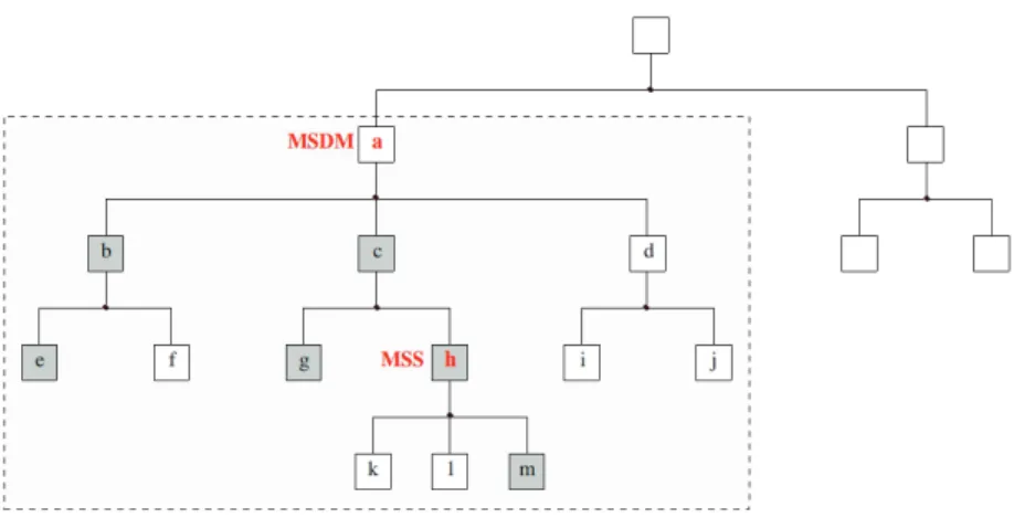
The Transformer example provides a first impression of a CBMMS built by hardware components. In reality, the behavior of these hardware components must be realized by software components. Our focus is on software compo-nents rather than hardware compocompo-nents. As a conceptual example, the left part of Figure 1.1 illustrates the hierarchical component structure of a typical CB-MMS. The system consists of three components: a, b and c. Component b is
composed of two other components: d and e. With respect to the terminol-ogy of CBSE, we distinguish two basic types of components: (1) a primitive
component, whose behavior is given directly by associated software, thus
can-not be further decomposed into other components; (2) a composite component which is a composition of other components. In Figure 1.1, a, c, d, and e are primitive components whereas Top and b are composite components. Since the component hierarchy has a tree structure, a composite component and its subcomponents have a parent-and-children relationship. For instance, b is the parent of d and e, which in turn are the children of b. Moreover, the system, i.e. Component Top, supports two modes: m1
Topand m2Top. When the system is in mode m1
Top, Component c is deactivated (i.e. not running), as the component hierarchy in Figure 1.1 shows by not displaying c in mode m1
Top. In contrast, when the system is in mode m2
Top, c is activated whilst e is deactivated. Be-sides, Component a has different mode-specific behaviors represented by black and grey colors in Figure 1.1. The right part of Figure 1.1, consistent with the left part, presents the connections between these components. A component is connected to another component via its input or output ports (squares in Figure 1.1).
Figure 1.1: A component-based multi-mode system
The system in Figure 1.1 is able to switch between its supported modes
m1
Top and m2Top. Figure 1.2 depicts its mode switch from m1Top to m2Top, starting at time t1 and ending at time t2. We call m1Top and m2Top stable
modes. During the mode switch within the interval [t1,t2], the system is in
1.1 Background and motivation 7 Figure 1.1, it can be observed that a CBMMS exhibits unique system behavior in each mode reflected by particular configurations of its components at vari-ous levels. The system mode switch is achieved by the joint mode switches of components composed together to form the complete system. For instance, the mode switch of the system from m1
Top to m2Top in Figure 1.1 corresponds to the following component mode switches:
• Component a changes its mode-specific behavior (indicated by the color
change from black to grey).
• Component e is informed to change its running status from "activated"
to "deactivated".
• Component b changes the running statuses and connections of its
sub-components (d and e) as well as the configuration of its ports (its second output port becomes activated in the new mode).
• Component c is informed to change its running status from "deactivated"
to "activated".
• Component Top changes the running statuses and connections of its
sub-components as well as the configuration of its ports.
Figure 1.2: Mode switch illustration We call this composable mode switch:
Definition 2. [Composable mode switch]: A composable mode switch is the
mode switch of an entire CBMMS or its subsystem represented by the joint mode switches of its components at various hierarchical levels.
A successful composable mode switch not only relies on the successful mode switch of each single component, but also relies on the correct synchro-nization and coordination of the mode switches of different components. Un-like the traditional mode switch problem, composable mode switch is novel.
Traditional mode switch handling usually does not assume systems built by reusable components, thus the mode switch is not composable and traditional approaches cannot be directly applied to composable mode switch. Further-more, traditional component-based systems usually do not consider multiple operational modes and mode switch. In this thesis, we have presented a mode switch mechanism, which we call the Mode Switch Logic (MSL). Parts and preliminary versions of our MSL have been presented in [17] [18]. MSL does not only allow the seamless composition of single-mode or multi-mode com-ponents but is also capable of handling the composable mode switch of CB-MMSs.
1.2 Problem description
1.2.1 Challenges of composable mode switch
The handling of composable mode switch is not trivial, as it poses multiple po-tential problems and challenges. Many contributing factors need to be consid-ered, such as component model, component hierarchy, component connection, system architecture and component execution pattern. The following are the major challenges that have to be addressed:
The component model
CBSE specifies that a software component must conform to a component model. A large number of component models have already been proposed tar-geting various application domains [12] [31]. Among these component models, only a few have multi-mode support, e.g. COMDES-II [34], MyCCM-HI [8], Rubus [24] and SaveCCM [25]. To compose multi-mode components in a CB-MMS, traditional component models must be extended, since in a CBMMS a component must be aware of its own modes which could be switched at run-time. In our MSL, we propose a mode-aware component model taking into account both the mode switch of a single component and the mode switch syn-chronization between different components.
Multi-mode component composition
A CBMMS or multi-mode component can be composed of both single-mode and multi-mode components. For a multi-mode component, its supported modes should also be composable. Since reusable components typically are
1.2 Problem description 9 developed independently, it is very likely that the supported modes and the number of supported modes differ between components. Hence, when a com-posite component is built by reusable components, the supported modes of each component are likely to be inconsistent with the desired modes of the composed component. Therefore, the mapping between the modes of different components must be defined during composition. In our MSL, this problem is settled by our mode mapping mechanism [19].
The mode switch runtime mechanism
A composable mode switch must be carried out under the guidance of some runtime mechanism that ensures correctness and efficiency. This is to a large extent neglected by existing mode switch handling approaches. Such a runtime mechanism includes many aspects, such as
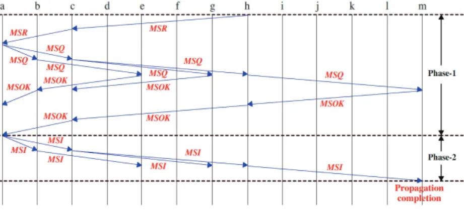
• Mode switch propagation: A mode switch can be triggered by any
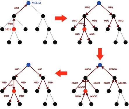
component and should be propagated to other components that also need to change their modes as a consequence. Since a component has no global knowledge of the system component hierarchy, a mode switch event cannot simply be broadcast from one component to all the other components. Instead, a stepwise propagation method is required. By taking advantage of the hierarchical component structure, a mode switch event can be directly or indirectly propagated to any related component. Later we shall show how this can be achieved by our Mode Switch Prop-agation (MSP) protocol1.
• The guarantee of consistent mode switch: The mode switch of a
sys-tem may correspond to the mode switches of many components. When the system completes a mode switch, all its components must be in a consistent state. For instance, components supposed to run in the new mode must not run in the old mode after the system has completed a mode switch. The MSP protocol plays a significant role in notifying dif-ferent components of the mode switch event, however, additional rules should be applied to guarantee the overall mode switch consistency. In our MSL, we have defined a mode switch dependency rule that guaran-tees a consistent mode switch.
• Mode switch and atomic execution: When a mode switch is triggered,
the CBMMS is supposed to stop running in the old mode and start its
mode switch as soon as possible. However, there could be ongoing exe-cutions in one or a set of components that cannot be aborted by a mode switch triggering. Our MSL handles such atomic component execution by an extended MSP protocol [22].
• Conflict handling for multiple mode switch triggering: Normally, a
CBMMS performs a mode switch rather swiftly, yet not instantaneously. Multiple mode switch triggering could happen either simultaneously or within a short interval. Without proper treatment, an ongoing mode switch could be compromised by the triggering of a new mode switch. In our MSL, the initial solution is to use an arbitration mechanism managed by a component with high authority to resolve the conflict [22]. Further details and a more general in-depth solution are included in our future work.
The timing analysis of a composable mode switch
Since most CBMMSs are also real-time systems, not only must the system functionality be correct, but also the timing constraints must be satisfied. In particular, the mode switch time must be bounded and analyzable. The mode switch time highly depends upon the mechanism implementing the composable mode switch.
1.2.2 Research goal
Since the composable mode switch of CBMMSs has been rarely exploited to date, our research goal boils down to:
Development of a systematic and practical approach which not only effec-tively and efficiently copes with the composable mode switch of CBMMSs, but also is amenable to analysis and verification of timing and functional correctness.
1.2.3 Research sub-goals
Our research goal is ambitious in the sense that it is the first attempt to realize the seamless composition of multi-mode components into CBMMSs as well as its mode switch handling. We decompose our research goal into a set of major research sub-goals (SGs):
1.3 Thesis contributions 11 SG1: To build a multi-mode system by single-mode or multi-mode components
in a composable manner.
SG2: To efficiently achieve a composable mode switch of a CBMMS. SG3: To analyze the mode switch time of a CBMMS.
1.3 Thesis contributions
The contribution of this thesis realizes the research sub-goals formulated above, including:
• A generic mode-aware component model which enables a multi-mode
component to support composable mode switch (forSG1).
• A mode mapping mechanism which can be easily implemented in each
composite component and overcome the mode incompatibility problem during composition (forSG1).
• A mode switch runtime mechanism capable of efficiently handling a
composable mode switch (forSG2).
• The timing analysis of composable mode switch guided by our MSL (for
SG3).
1.4 Publications
This thesis stems from a number of publications. The following gives a brief introduction of the publications contributing to the backbone of this thesis and the complete list of publications can be found in "List of publications" at the beginning of the thesis.
1.Composable mode switch for component-based systems, Yin Hang, Eti-enne Borde, Hans Hansson, 3rd Workshop on Adaptive and Reconfigurable Embedded Systems (APRES 2011), p 19-22, Editor(s): Sebastian Fischmeis-ter, Linh TX Phan, April, 2011
and effort by allowing systems to be built from pre-developed reusable com-ponents. A classical approach to reduce embedded systems design and run-time complexity is to partition the behavior into a set of major system modes. In supporting system modes in CBD, a key issue is seamless composition of multi-mode components into systems.
In addressing this issue, we present a mode switch logic and algorithm for component-based multi-mode systems. The algorithm implements seam-less coordination and synchronization of mode switch in systems composed of independently developed components. The paper provides formally defined semantics covering aspects relevant for mode switch, together with algorithms implementing mode switch rules for different types of components. The ap-proach is illustrated by a simple example.
Thesis contribution: This paper proposes the initial version of our MSL, in-cluding the mode-aware component model, mode switch propagation and the mode switch dependency rule. It contributes to chapters 2 and 3.
My contribution: Yin Hang is the main contributor and main author of this paper, inspired by the useful comments and suggestions from Etienne Borde and Hans Hansson.
2.A mode mapping mechanism for component-based multi-mode systems, Yin Hang, Hans Hansson, 4th Workshop on Compositional Theory and Tech-nology for Real-Time Embedded Systems (CRTS 2011), p 38-45, Editor(s): Robert I. Davis and Linh T.X. Phan, November, 2011
Abstract: Component-Based Development (CBD) reduces development time and effort by allowing systems to be built from pre-developed reusable com-ponents. A classical approach to reduce embedded systems design and run-time complexity is to partition the behavior into a set of major system modes. In supporting system modes in CBD, a key issue is seamless composition of multi-mode components into systems. In addressing this issue, we previously developed a Mode Switch Logic (MSL) for component-based multi-mode sys-tems. Our MSL implements seamless coordination and synchronization of mode switch in systems composed of independently developed components. However, our original MSL is based on the, in a setting of reusable compo-nents, unrealistic assumption, that all the components of a system support the same modes. This considerably limits the feasibility of our MSL. In this paper we lift this assumption and propose a mode mapping mechanism that enables assembly of components supporting different sets of modes. We demonstrate our mode mapping mechanism by a simple example application.
1.4 Publications 13 Thesis contribution: This paper identifies the mode incompatibility problem of composing multi-mode components and proposes a mode mapping mecha-nism as the corresponding solution. It contributes to Chapter 4.
My contribution: Yin Hang is the main contributor and main author of this paper. This work is carried out in close cooperation with Hans Hansson. 3. Towards mode switch handling in component-based multi-mode sys-tems, Yin Hang, Jan Carlson, Hans Hansson, 15th International ACM SIG-SOFT Symposium on Component Based Software Engineering (CBSE 2012), p 183-188, Editor(s): Nenad Medvidovic and Magnus Larsson, June, 2012 Abstract: Component-Based Software Engineering (CBSE) is becoming a prominent solution to the development of complex embedded systems. Mean-while, partitioning system behavior into different modes is an effective ap-proach to reduce system complexity. Combining the two, we get a component-based multi-mode system, for which a key issue is its mode switch handling. The mode switch of such a system corresponds to the joint mode switches of many hierarchically organized components. Such a composable mode switch is not trivial as it amounts to the mode switch coordination of different com-ponents. In this paper, we identify the major challenges of the composable mode switch handling and classify existing approaches with respect to how they handle these challenges. We also provide a more detailed presentation of the corresponding solutions included in our approach – the Mode Switch Logic (MSL).
Thesis contribution: This paper identifies the major challenges of handling the mode switch of a CBMMS and classifies a number of existing component models in terms of their mode switch handling. Moreover, this paper also revises the mode-aware component model, the MSP protocol and the mode switch dependency rule of MSL. It contributes to chapters 1, 2 and 3.
My contribution: Yin Hang is the main contributor and main author of this paper. This work is inspired by the intensive discussion with Jan Carlson and Hans Hansson.
4.Timing analysis for mode switch in component-based multi-mode sys-tems, Yin Hang, Hans Hansson, 24th Euromicro Conference on Real-Time Systems (ECRTS 2012), p 255-264, Editor(s): Robert I. Davis, July, 2012. Abstract: Component-Based Development (CBD) reduces development time and effort by allowing systems to be built from pre-developed reusable
compo-nents. Partitioning the behavior into a set of major operational modes is a clas-sical approach to reduce complexity of embedded systems design and execu-tion. In supporting system modes in CBD, a key issue is seamless composition of pre-developed multi-mode components into systems. We have previously developed a Mode Switch Logic (MSL) for component-based multi-mode sys-tems implementing such seamless composition.
In this paper we extend our MSL to cope with atomic transactions, i.e., to handle sets of components that must not be aborted in the middle of the processing of data. This is in contrast with our original MSL, in which components are immediately aborted to perform a mode switch. Based on our extended MSL, we provide analysis of the mode switch timing.
Thesis contribution: This paper extends MSL by taking atomic component execution into account and performs the mode switch timing analysis for MSL. A preliminary approach is also proposed to resolve the conflict due to multiple mode switch triggering. It mainly contributes to chapters 5 and 7. My contribution: Yin Hang is the main contributor and main author of this paper. This work is carried out in close cooperation with Hans Hansson.
1.5 Research methodology
The methodology adopted in our research can be summarized as follows:
• Literature review is always a key preliminary step before a research goal
or sub-goal is established. Investigated works are mostly related to mode switch problems, CBSE, and adaptive embedded systems.
• Once the research goal is identified, a couple of sub-goals are proposed.
A research goal is usually further divided into a couple of sub-problems which can be handled separately. We can simplify a problem by initially making simplifying assumptions. Once we come up with a solution, some assumptions will be lifted to yield a more realistic solu-tion. This process may iterate several times as the solution is incremen-tally developed.
• Each proposed solution is initially evaluated and verified via the
mod-eling of some representative conceptual examples which are helpful for spotting potential design errors and the refinement and revision of the
1.6 Thesis outline 15 corresponding solution. Currently the evaluation is mostly based on the extensive use of UPPAAL [37] modeling and verification. However, we also intend to perform extensive evaluation in future.
• We publish our research results yielded at different stages. This
dissem-ination provides feedback and discussion that helps refine and shape our research. For instance, reviewers’ feedback and discussions with fel-low researchers at conferences is instrumental in identifying underlying problems that we have overlooked, and could also suggest improvements and relevant literature in neighboring areas.
The research methodology is further illustrated in Figure 1.3.
Figure 1.3: Research methodology
1.6 Thesis outline
This thesis is a monograph consisting of 10 chapters and the outline of the rest of the thesis is organized as follows:
• Chapter 2 — The mode-aware component model: introduces the
mode-aware component model for both primitive and composite compo-nents. The mode-aware component model is generic and can be applied as a mode switch extension to many existing component models.
• Chapter 3 — The mode switch runtime mechanism: elaborates how
a composable mode switch is handled at runtime. The mode switch run-time mechanism in this chapter includes the Mode Switch Propagation
(MSP) protocol and the mode switch dependency rule. The MSP pro-tocol propagates the mode switch request from a component to all other related components. The mode switch dependency rule guarantees the mode consistency between different components after each mode switch.
• Chapter 4 — Mode mapping: describes the mode mapping mechanism
of MSL for overcoming the mode incompatibility problem for compos-ing multi-mode components. The purpose of mode mappcompos-ing is twofold. First, it maps the modes of different components during the composi-tion. Second, it derives the new mode of each component at runtime in cooperation with the MSP protocol.
• Chapter 5 — The handling of atomic component execution: extends
the MSP protocol by introducing the support for atomic component exe-cution.
• Chapter 6 — Algorithms for the mode switch runtime mechanism:
implements the mode switch runtime mechanism as algorithms for prim-itive components, non-composite components and the top component, respectively.
• Chapter 7 — The composable mode switch timing analysis:
per-forms the mode switch timing analysis based on our MSL. Further-more, a model-checking approach is devised to obtain the worst-case atomic component execution time assuming the pipe-and-filter architec-tural style.
• Chapter 8 — Case study–An Adaptive Cruise Control system:
demonstrates the usage of MSL in a case study, an Adaptive Cruise Con-trol (ACC) system which is theoretically designed as a CBMMS in the thesis.
• Chapter 9 — Related work: presents existing work related to our MSL
in various research domains such as component models, real-time sys-tems and specification languages.
• Chapter 10 — Conclusions and future work: summarizes the thesis
and discusses the future work. Additionally, the evolution trace of MSL is also provided.
Chapter 2
The mode-aware component
model
Traditionally, CBSE assumes the composition of single-mode components. In addition to this, a CBMMS or a multi-mode component should allow the com-position of both single-mode and multi-mode components. This imposes extra requirement on the component model and the composition process. A mode-aware (or multi-mode) component is different from traditional components in terms of the interface, internal properties, and many other aspects. In this chap-ter, we propose a mode-aware component model for both primitive and com-posite components. This component model is rather generic, with emphasis on modes and mode switch. It is not intended as a complete component model, rather as a basis for mode-aware extensions of existing component models that cover a more complete set of features.
2.1 The mode-aware component model and its
definition
Just like traditional port-based component models, both primitive and compos-ite components in our component model have a set of ports to communicate with neighboring components. Furthermore,
• Both primitive and composite components support one or more modes.
Each mode of a multi-mode component is associated with a unique mode 17
identifier (ID).
• A primitive component has a dedicated mode switch port for the
commu-nication with its parent during a mode switch. A composite component has an additional dedicated port for the communication with its subcom-ponents/children.
• Both primitive and composite components have a separate
configura-tion in each mode. A component configuraconfigura-tion is a collecconfigura-tion of mode-specific information such as the mode-mode-specific functional behavior and mode-related properties of a component, as well as mode-independent information.
• A component starts to reconfigure itself by changing its configuration
to the configuration in the new mode during a mode switch. The mode switch of a component is controlled by the runtime mechanism of MSL integrated in the component.
Let P C denote the set of primitive components and CC denote the set of composite components of a CBMMS. In the following, the formal definition of the mode-aware component model will be given for primitive components and composite components, respectively.
Definition 3. [Mode-aware primitive component]: A mode-aware primitive
component ci∈ P C is a tuple:
<IP, OP, pMSX,B, MIP, MDEFP, m, MB, AIP, AOP, MS, MP, MSRM > where IP is the set of input ports of ci; OP is the set of output ports of ci; pMSX∈/ (IP ∪ OP) is a dedicated bidirectional mode switch port for exchanging
mode-related information with the parent; B is the set of mode-specific behaviors of ci; MIP is the set of mode-independent properties of ci(including M, the
set of supported modes of ci.); MDEFP is the set of mode-dependent
Extra-Functional Properties (EFPs) of ci; m is the current mode of ci; the function MB : M → B defines the functional behavior of ciin each mode; the function AIP : M → 2IP defines the set of activated input ports of ci in each mode;
the function AOP : M → 2OP defines the set of activated output ports of ci
in each mode; the function MS : M → {Activated, Deactivated} indicates the running status1 (either activated or deactivated) of c
i in each mode; the
1The running status of a component c
ican be considered as a property in a specific mode, as
is defined here. Alternatively, the deactivated running status of cimay also be considered as a
2.1 The mode-aware component model and its definition 19
function MP : M × MDEFP → Q assigns values to each mode-dependent EFP of ci in each mode, where the set Q is such that for a mode m and a
mode-dependent EFP e, MP(m, e) ∈ dom(e)—the range of values of e; MSRM is the mode switch runtime mechanism of ci.
Since pMSX is dedicated to mode switch, we separate it from IP and OP.
MSRM is used to control the mode switch of ci and will be defined in Chap-ter 3. It should be noted that MSRM in the tuple above can be considered as an internal controller of ci. When ciis used in a specific context, the MSRM of ci should not be exposed like its mode information and EFPs. Besides,
Definition 4. The MIP of a mode-aware primitive component ci is another
tuple:
<M, m0,MIEFP >
where M as explained above is the set of supported modes of ci; m0 is the
initial mode of ci; MIEFP is the set of mode-independent EFPs of ci.
Actually, MIEFP and MDEFP of ciare two disjoint sets and their union is
EFP, i.e. the set of all EFPs of ci. EFP, sometimes also called non-functional property, is a key concept in CBSE. An EFP is not related to the functional aspect of a system. Instead, it covers aspects such as performance and de-pendability. An EFP can be associated with one or more parameters. When the parameter value(s) of an EFP is(are) mode-dependent, this EFP belongs to MDEFP. Otherwise, it belongs to MIEFP. The following lists a couple of typical EFPs:
• Resource consumption. This EFP defines the resource requirement of
a component. The resource here can be power, CPU cycles, memory, bandwidth or others. If a multi-mode component consumes different amount of resources in different modes, then resource consumption be-longs to MDEFP.
• Atomicity. If the execution of a component is atomic, it cannot be
in-terrupted by any other event before completion. If the execution of a component is non-atomic, then it can be interrupted by another event at any time. In Chapter 5, atomic component execution will be revisited and we shall present how it is handled in our MSL.
• Real-time properties, such as Worst-Case Execution Time (WCET),
trig-gering period, maximum and minimum time for the component to stay in one mode, and even scheduling policy.
Please note that it is possible to define the scheduling policy as an EFP for a component which then can have its own scheduler. This is to some extent congruous with hierarchical scheduling [13]. Compared with a primitive com-ponent, the mode-aware component model of a composite component is more complex, since a composite component must know the essential information of itself, its subcomponents and how they are composed.
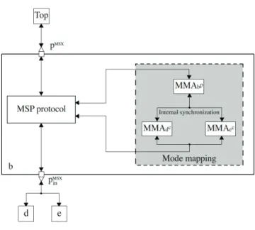
Definition 5. [Mode-aware composite component]: A mode-aware composite
component ci∈ CC is a tuple:
<IP, OP, pMSX, pMSX
in ,SC, Con, MIP, MDEFP, m,
AIP, AOP, MS, ASC, DSC, ACon, MP, MSRM >
where IP, OP, pMSX, MDEFP, m, AIP, AOP, MS, MP and MSRM are defined as in Definition 3; pMSX
in is a second dedicated mode switch port for exchanging mode-related information with the children of ci; SC is the set the
subcompo-nents of ci; Con ⊆ (PSC∪ IP ∪ OP) × (PSC∪ IP ∪ OP) is the set of all inner
component connections of ciin all modes, where PSCis the set of ports of SC:
PSC = ∀cj∈SCci
IPcj ∪ OPcj;
MIP is the set of mode-independent EFPs of ci as defined in Definition 6; the
function ASC : M → 2SC indicates the activated subcomponents of ciin each
mode; the function DSC : M → 2SC indicates the deactivated subcomponents of ciin each mode; the function ACon : M → 2Con defines the set of activated
inner component connections (connections in use) of ciin each mode. Two dedicated mode switch ports are defined for a composite component because a composite component must be able to communicate with both its parent and children during a mode switch. It should be noted that some of the elements in the tuple for ci ∈ CC are essential for the mode switch handling of cibut should not be exposed for component reuse, including SC, Con, ASC,
DSC, ACon, and MSRM. Besides,
Definition 6. The MIP of a mode-aware composite component ci is another
tuple:
<M, m0,M
SC, m0SC, mSC,MM, MIEFP >
where M, m0 and MIEFP are defined as in Definition 4; the function MSC :
SC → 2Mmaps each subcomponent of c
2.1 The mode-aware component model and its definition 21
modes (M is the set of all modes supported by ci and SCci); the function
m0
SC : SC → 2M maps each subcomponent of cito the corresponding initial
mode; the function mSC : SC → 2M maps each subcomponent of ci to the
corresponding current mode; MM is the mode mapping between ci and SCci
and will be further explained later in Chapter 4.
In the tuple for the MIP of ci ∈ CC, elements MSC, m0SC, mSC, and MM
should not be exposed for component reuse. The MIEFP and MDEFP of ci ∈
CC can be exposed for component reuse because the EFPs of ci has been derived based on the EFPs of its subcomponents.
Our mode-aware component model for primitive and composite compo-nents are illustrated in figures 2.1 and 2.2, where the similarity and discrepancy of primitive and composite components can be easily perceived. Generally speaking, this component model assumes the pipe-and-filter type of communi-cation and it is data-driven rather than control-driven [38]. Yet the model itself should be able to support both data-driven and control-driven computation pat-terns. In both figures, p0
in· · · pmindenote the input ports and p0out· · · pnoutdenote the output ports. pMSXand pMSX
in are the dedicated mode switch ports. A unique configuration is defined for each mode k and the included elements for each configuration are rather consistent with the aforementioned definitions.