FACULTY OF ENGINEERING AND SUSTAINABLE DEVELOPMENT
.
Traffic Model Based Energy Efficient Radio Access
Network
Mazz Ahmed Mohamed Ahmed
June 2015
Master’s Thesis in Electronics
Acknowledgement
I would like to express my sincere gratitude to my advisor Dr. Mohamed Hamid for his continuous support, guidance and for improving my thesis work and my research capacity through his extensive knowledge. I would also like to thank all my friends and colleagues for creating an amazing and incredibly friendly environment during my studies in Sweden.
Last, but by no means least, I would like to give the biggest thanks to my parents Haj Ahmed and Al sit Al Nazra Fayga, my brother Jiloon, my sisters Solafa and Leena. I am especially indebted to you for your unequivocal support, guidance, patience, encouragement and unconditional love as always, for which my mere expression of thanks likewise does not suffice.
Abstract
As the concerns about global energy consumption increased the matter of energy consumption in Radio Access Networks (RANs) became an important issue especially with the exponential growth in demanded traffic. This interest of developing innovative technologies to reduce the expected energy consumption by the mobile communication sector was driven by environmental concerns and cost reduction.
The aim of this thesis is to introduce a new methodology to make the Radio Access Network (RAN) more energy efficient based on jointly the demanded throughput and a realistic traffic profile. Furthermore, to find a metric that quantifies the relation between the Energy Efficiency (EE), Spectrum Efficiency (SE) and demanded throughput.
The proposed methodology for reducing the energy consumption in the RAN characterizes the offered throughput in order to determine the sufficient energy needed. The manner for reducing the energy consumed by the RAN is simply by switching (OFF/ON) Base Stations (BSs) based on the demanded throughput which introduces an energy efficient RAN.
The results show a significant reduction in the energy consumption with regard to the demanded traffic. Moreover, it gives a measure of the EE with consideration to the SE which enhances the performance evaluation from an EE point of view during the RAN planning phase.
Table of contents
Acknowledgement ... i
Abstract ... iii
Table of contents ... iv
List of Tables ... vi
List of Figures ... vii
List of Abbreviations ... viii
1 Introduction ...9 1.1 Background ...9 1.2 Problem Formulation ... 10 1.3 Related Work ... 11 1.4 Contribution Overview ... 12 1.5 Thesis Layout ... 12 2 System Model ... 14 2.1 Propagation Model ... 15 2.2 Performance Metrics... 16
3 Process and Methodology ... 18
3.1 Assumptions ... 18
3.1.1 RAN Information ... 18
3.1.2 Simulation Parameters ... 20
3.2 Energy Efficient Operation Algorithm ... 21
4 Results and Discussion ... 25
4.1 System Layout ... 25
4.1.1 RAN Operation ... 25
4.1.2 System Initialization ... 25
4.2 Algorithm Implementation ... 26
4.2.1 Traffic Model... 26
4.2.3 Grade of Service ... 27
4.2.4 Energy Efficient Operation ... 27
4.2.5 Energy Efficiency Evaluation ... 28
5 Conclusions ... 30
5.1 Concluding Remarks ... 30
5.2 Recommendations for Future Work ... 30
References ... 32 Appendix A ... C1
List of Tables
Table 1. System parameters ... 20
Table 2. RAN Demanded Throughput ... 27
Table 3. RAN Demanded Throughput with Regard to GoS ... 27
Table 4. Energy Efficient RAN Decision ... 28
List of Figures
Fig. 1. Monthly global mobile traffic (voice and data), 2014-2020 [1]. ...9
Fig. 2. Global RAN electricity consumption projected until 2020 for different scenarios of RAN development.[2]. ... 10
Fig. 3. SE-EE trade-off. [10]. ... 12
Fig. 4. RAN Operation of 3 BSs. ... 14
Fig. 5. Deployment of BSs in an area of 5 Km2 for proposed RAN (a)9 BSs, (b)25 BSs, (c)49 BSs and (d)81 BSs . ... 19
Fig. 6. Duty cycle through a week of measurements, from Monday, 2013,09,30 to Sunday, 2013, 10,06. [18]. ... 20
Fig. 7. Energy Efficient Operation Algorithm. ... 21
Fig. 8. Traffic Modelling Process ... 22
Fig. 9. Operation of RAN in an area of 5 Km2 (a)9 BSs, (b)25 BSs... 25
List of Abbreviations
3GPP 3rd Generation Partnership Project
BS Base Station
EARTH Energy Aware Radio and network tecHnologies ECR Energy Consumption Ratio
EE Energy Efficiency Eembodied Embodied Energy
EER Energy Efficiency Ratio Eop Operation Energy
E3F Energy Efficiency Evaluation Framework GoS Grade of Service
GR Green Radio
KPI Key Performance Indicator LTE Long Term Evolution MS Mobile Station
OPERA-NET Optimising Power Efficiency in mobile Radio NETworks RAN Radio Access Network
SE Spectrum Efficiency SIR Signal to Interference Ratio
1 Introduction
1.1 Background
Mobile communication networks have been experiencing a rapidly increasing demand for higher data rates in wireless access. This huge demand is a product of the continued growth in the number of mobile broadband subscriptions and the advancements in mobile industry.
Fig. 1 [1] depicts the monthly global mobile traffic growth for voice and data since 2014 with a forecast till 2020. Beside the growing demand of high throughput it’s observed that data traffic dominated the mobile services, the volume of global mobile data traffic exceeded the voice traffic in 2009 and expected to dominate all mobile traffic by 2020 with new smartphones subscribers and exchanging basic phones for smartphones [1, 2].
Fig.1. Monthly global mobile traffic (voice and data), 2014-2020 [1].
This rapid increasing demand for higher throughput is faced by deploying more Base Stations (BSs) which comes with the price of increase in energy consumption. Mobile communication networks are estimated to consume 0.5 percent of the global energy supply [3], furthermore the global carbon footprint for mobile communication is predicted to increase by a factor of three between 2007 and 2020 in CO2 emissions having the mobile devices production and global Radio Access Network
(RAN) operation as the main contributors [2].
All these concerns of energy consumption have substantially attracted researchers in both academia and industry. Fig. 2 illustrates the global RAN electricity consumption prediction for 2020 for different scenarios in energy efficiency improvement.
Fig.2. Global RAN electricity consumption projected until 2020 for different scenarios of RAN development. [2].
As depicted by Fig. 2, different scenarios for electricity consumption figures are illustrated. For the first scenario an expected increase from 49 TWh in 2007 to about 109 TWh in 2020 in case of no energy efficiency improvements implemented in global RAN operation. On the other hand energy savings of 10 percent is expected in the second scenario from the continuous improvements in RAN energy consumption which introduced to the network by rolling out new sites.
Another 10 percent energy consumption reduction is expected in the third scenario in the ground of additional energy efficiency innovations assuming an efficiency gain of 50 percent per site is obtained. The use of alternative energy after 2012 introduce a small additional reduction to the previous scenarios due to the small number of off-grid sites (alternative energy sites) installed compared to the existing ones. In the fifth scenario an additional 50 percent energy savings is expected compared to the second scenario in the case where the BS equipment are optimized for energy efficiency. Therefore, it is possible to sustain or impatiently decrease the RAN energy consumption prediction from 2007 till 2020 by applying more energy efficient technologies with adaption to the rapid global growth in data traffic.
1.2 Problem Formulation
Motivated by the great importance of energy saving management research activities to the future environment protection, the 3rd Generation Partnership Project (3GPP) raised the voices calling for more attention to Energy Efficiency (EE) in new RAN technologies.
The energy consumed by a BS is modeled as the entirety of the Embodied Energy (Eembodied) and the
Operating Energy (Eop). The Eembodied is the energy consumed by all the processes associated with the
BS manufacturing while the Eop is the energy consumed due to the BS operation. It is found that
reducing the Operational Expenditure concerns the mobile network operators more than reducing the Capital expenditures and since the Eop has a direct impact on the Operational Expenditure, the Eop
dominates most of the research activities related to energy consumption reduction in RAN [4].
The Eop has two parts, the energy used to operate the BS and the energy employed in signal
transmission. This thesis target is to study and proposes a methodology that reduces the energy consumed due to signal transmission.
1.3 Related Work
Many initiatives came to the light since the emerging awareness of the importance of EE in new RAN technologies to meet the demand for more energy efficient deployments in radio communication. The Energy Aware Radio and neTwork tecHnologies (EARTH) provided the Energy Efficiency Evaluation Framework (E3F) which identified the building blocks for a holistic energy efficiency assessment with regard to the 3GPP evaluation framework for Long Term Evolution (LTE). The principle of the E3Fenhancements includes a realistic BS power model for various BS types and long term traffic models to describe load fluctuations over a day [5,6].
Furthermore, several projects and workshops in both academia and industry dedicated to enhance the energy efficiency in radio communication have been concentrating recently in this relatively new trend which is now known as Green Radio (GR). The contributions of these projects along with their vision are showing the emerge of great interest to invest more in GR technologies.
Optimising Power Efficiency in mobile RAdio NETworks (OPERA-NET) project in their 2020 GR vision provided an estimated findings of 20 percent EE is achieved using two approaches, smart power management in RAN and BS consumption optimization [7].Moreover, eWIN namely, (Energy-efficient Wireless Networking) project aims to develop energy (Energy-efficient wireless networking principles and decrease the energy usage in upcoming and current wireless standards [8].
One of the main concerns regarding previous and ongoing researches in Eop reduction that it suggests
powering down underutilized BSs in the minimum traffic load periods. On the other hand increasing the operating power of the active BSs come as a solution to compensate for the powered down ones. Although the findings of these researches showed operating energy savings of 25-30 percent has been achieved [9], the increment in operating power is usually neglected which limits future chances for operating power optimization that leads to higher EE rate.
1.4 Contribution Overview
Any research formulated within the EE approach for RAN consist the study of different aspects affecting the energy consumption. In this thesis SE and EE are the only aspects considered for the proposed methodology. From a wireless network optimization point of view the system throughput per unit of bandwidth which formulates the SE is considered a very accepted metric and among the Key Performance Indicators (KPIs) of 3GPP while the EE did not get the same importance as a KPI. Therefore, the SE-EE tradeoff become an important input to formulate present and future GR contributions since the SE-EE tradeoff does not always concur with the major trend for GR technologies [10].
Fig. 3 illustrate the relation between EE and SE in a point to point transmission system, it is shown that with higher SE a lower EE is expected. However in practical systems the SE-EE relation is not as simple as shown in Fig. 3 since the transmission condition such as transmission distance, modulation and coding scheme and radio resource management algorithms will impact the illustrated relation between SE and EE. Moreover, from [10], in a multiuser/multicell scenario the interference power generated from neighboring cells will degrade the SE and EE. Therefore, a systematic approach to develop an SE-EE relation is needed to fulfill all the multiuser/multicell scenario characteristics including the interference generated within a multiuser/multicell system.
Fig.3. SE-EE trade-off. [10].
The proposed methodology used as a solution in respect of the expected contradiction of using the prescribed SE-EE tradeoff in a multiuser/multicell scenario. Moreover, it investigates the ability to frame an energy efficient RAN deployment with consideration to the Grade of Service (GoS) and also capturing and quantifying the energy savings in the RAN.
1.5 Thesis Layout
The thesis is divided into five sections. Section 2 introduces the system model of the proposed methodology and the motivation to its usage. Section 3 presents the process and methodology for the energy efficient RAN proposed in details along with a preview of the algorithm to follow. In Section 4
the results of the proposed methodology are presented and discussed. Finally, Section 5 concludes the thesis and proposes some possible directions for future continuation.
2 System Model
In this section the system model behind the proposed methodology is presented and discussed. The proposed methodology is based on characterizing the throughput within the RAN. As illustrated in Fig. 4a Mobile Station (MS) is located in a RAN operation consist of three BSs. The MS is assigned to BS1 since it is the closest BS therefore, BS2 and BS3 are interfering to the signal received by the MS from BS1.
Adding more BSs to the network in Fig. 4 will result in higher interference received by the MS i.e. lower Signal to Interference Ratio (SIR). This implies an expected reduction in the offered throughput by the RAN operation and moreover, more energy is consumed by increasing the RAN operation. The SIR experienced at the MS is then used to calculate the throughput per user. Thereafter, The RAN offered throughput is also calculated to determine how many BSs are required to sufficiently cover the RAN demanded throughput. After that, other performance metrics are used to calculate the energy consumption and also to compare between different RAN operations with regard to energy efficiency.
2.1 Propagation Model
The received signal from the BS to the MS is calculated using the propagation model used in [11] and expressed as:
Pr = Pt - Lp (dB) (1)
All in dB scale Where
Pr is the received power.
Lp is the propagation loss between the MS and the BS.
Pt is the transmitted power.
Eq. (1) is used in this thesis under the assumption that all the internal losses in both the receiver and transmitter terminals are included within both Pr and Pt.
In order to treat the received signal with relation to a propagation loss model that is consistent with the proposed RAN scenario, Eq.(2) [12] is used as the propagation loss model in this thesis , this propagation loss model was chosen due to its relevancy with the proposed system assumption as presented in Section 3.
Lp=PLb+PLtw+PLin (dB) (2)
All in dB scale Where
Lp is the total propagation loss.
PLb is the basic propagation loss.
PLtw is the loss through wall.
PLin is the indoor loss.
Also from [12] PLb can be found as in Eq.(3) follows
PLb=36.7log10(d)+22.7+26log10(fc) (dB) (3)
Where
d is the distance between the BS and the MS in meter. fc is the carrier frequency in GHz.
Moreover, PLtw and PLin values are stated empirically for a dense urban area in [12] as following:
PLtw= 20 (dB)
PLin = 0.5 din(dB)
Where
din is the indoor distance between the wall and the MS and assumed to be 10m.
Plugging Eq.(3), PLtw and PLin into Eq.(2) gives:
Which is the propagation loss model used throughout this thesis.
The distribution of the propagation loss values for a wide range of distances tend to be a log-normal distribution where the propagation model is a function of the distance d between the transmitter and receiver (downlink) as stated in [13] and shown below in Eq.(5)
Lp(d)=𝐿𝑝 (𝑑)+X(dB) (5)
Where
Xis zero mean log-normally distributed random variable with standard deviation in dB.
𝐿𝑝
(𝑑) is the arithmetic mean value of the propagation loss as a function of distance.
The standard deviation value for the propagation loss model in Eq. (4) is 7 dB as shown in [12] where the mean value of the calculated propagation loss is log-normally distributed with zero mean and a standard deviation of 7 dB to account for the shadow fading introduced in the RAN operation.
2.2 Performance Metrics
The traffic and EE metrics used throughout this thesis consist of a sequential calculation starting with the traffic throughput evaluation framework and followed by the Energy Consumption Ratio (ECR) evaluation framework.
The Shannon-Hartley theorem state that if S is the average transmitter power, and the noise is white thermal noise of power in the bandwidth W, Then it is possible to transmit binary digits with a highest bound of a rate of C as shown in Eq. (6) [14]
C=Wlog2(1 + 𝑆 +𝐼) (bits/second) (6) Where C is channel capacity. W is signal bandwidth. S is received signal power. is noise power.
I is interference signal power.
In this thesis Eq. (6) is used under the bandwidth normalization condition with another distinction that is because of cellular systems are interference-limited [15].Therefore, the noise is dominated by the interference and the channel capacity model then become as in Eq. (7).
C=log2 (1 +
𝑆
𝐼) (bits/second/Hz) (7) To come up with a firm evaluation of the proposed methodology there is a need to specify the EE metrics used for this purpose. In [16,17] the Energy Consumption Ratio (ECR) is defined as the energy consumed normalized to the effective throughput as shown in Eq. (8), this approach makes it a convenient EE metric for the proposed methodology since it gives an insight of how much energy is
needed to transmit a number of information bits by the RAN which is translated to a traffic based energy consumption metric.
ECR = E/T (Joule/bit/Hz) (8) Where
T is the offered throughput. E is the consumed energy in joule.
The energy consumed by the RAN is calculated through multiplying the energy consumption in a single BS by the total number of operational BSs under the assumption that the RAN is homogeneous regarding the handled traffic Eq.(9)
ERAN=EBS×NOperational BSs (Joule) (9)
Where
ERAN is the energy consumed by the RAN.
EBS is the energy consumed by a single BS.
NOperational BSs is number of operational BSs.
Moreover, to provide a different prospective for the energy performance evaluation another EE metric is introduced. The Energy Efficiency Ratio (EER) is simply the inversion of the ECR. This EE metric gives an important insight of the energy utilization in a RAN. In other words this metric evaluates the RAN performance by providing the number of transmitted bits of information when consuming one joule of energy as shown in Eq. (10).
EER= 1
3 Process and Methodology
Before stating the parameters and conditions assumed for the process of proposed methodology, some assumptions are taken into account. In this section the assumptions and system parameters are presented and discussed followed by the algorithm for the proposed methodology.
3.1 Assumptions
3.1.1 RAN Information
The RAN operation area is assumed to be located in a dense urban area. For the reason that a RAN serving a dense urban area naturally provides more throughput than a RAN serving a rural area it is expected to be more energy consuming which makes a typical testing scenario for most approaches targeting energy consumption reduction in RAN. This is due to having more number of active users requires more RAN throughput to handle which lead to more energy consumption.
The area under consideration is assumed to be squared area as well as the RAN operation deployment where the BSs of the RAN are deployed in the form of a square with M BSs in its side where M =3:16, Fig. 5 shows the proposed RAN operation for M= 3,5,7,9.
Furthermore, on account that the area is dense urban, the dominant factor for the network dimensioning is the RAN offered throughput. Therefore, it is also the dominant factor affecting the network performance [18].
Fig.5. Deployment of BSs in an area of 5 Km2 for proposed RAN (a)9 BSs, (b)25 BSs, (c)49 BSs and (d)81 BSs .
As stated in [10], the dominant factor regarding the GoS in micro/Pico cells is the RAN offered throughput. In other words, in dense urban areas where the need for offered throughput exceed the need for RAN coverage the offered throughput become the dominant factor affecting the RAN GoS. This statement supports the path taken throughout this thesis which gives less attention to the RAN coverage issue.
Furthermore, to account for GoS, a typical 30 percent value were taken into account meaning that the RAN Demanded throughput (CDemanded) should equal to 30 percent of the RAN Offered throughput
(COffered) to ensure the GoS of the RAN as shown in Eq. (11).
COffered = 3.33×𝐶𝐷𝑒𝑚𝑎𝑛𝑑𝑒𝑑 (bit/second/Hz) (11) Where
COffered is the RAN offered throughput
𝐶𝐷𝑒𝑚𝑎𝑛𝑑𝑒𝑑 is the RAN demanded throughput
(b)
3.1.2 Simulation Parameters
3.1.2.1 RAN Parameters
Table (1) presents the simulation parameters used to test the proposed methodology. The users are uniformly distributed around the RAN deployment area. Furthermore, the communication system considered is LTE where the frequency reuse factor is 1, in Section 5 more suggestions are given regarding the applications for this methodology.
Table 1.System parameters
Parameter Value
Area 5 Km2
Number of Users 10000 Users Distribution Uniform Transmitted Power 40 dBm Cellular Standard LTE
Frequency 2.6 GHz Average Demanded Throughput per user 10 [bit/s/Hz] uncoded
3.1.2.2 Traffic Profile
In [19] a measurement campaign was carried out in Kista, Stockholm, Sweden to obtain LTE traffic profile through a week. As depicted in Fig. 6the traffic profile is changing with time during the day and for the whole week and observably decreases during the weekend which give the sense of a typical dense urban RAN traffic profile.
Fig.6. Duty cycle through a week of measurements, from Monday, 2013,09,30 to Sunday, 2013, 10,06. [18].
For simplicity the duty cycle measurements of one day is used for simulation, specifically the day with the highest duty cycle which found to be Friday 04 October 2013 as shown in Fig. 6. It is important to mention that the span for these measurements is four hours for every plotted point meaning every duty cycle value is taken for a four hours period.
D ut y C yc le [ % ]
3.2 Energy Efficient Operation Algorithm
In order to throw a light on the methodology under consideration a flowchart of the algorithm used for the energy efficient operation is presented and followed by detailed explanation. Fig. 7 illustrates the processes forming the proposed methodology, this methodology is combined from three main sub processes, the traffic model (2), the RAN offered throughput lookup table (8, a) and the energy metric (8, c) as depicted in Fig. 7.
Fig.7.Energy Efficient Operation Algorithm.
The process starts in a predefined time and begins with the traffic model process. The traffic model is a very important process giving that it provides the needed information to decide which operation is more energy efficient. Fig. 8 illustrates the building blocks forming the traffic model.
As shown in Fig. 8the traffic model start with two inputs (2,1,a) and (2,1,b) respectively represent the user distribution information and the current RAN operation information. Thereafter, these information parameters both plugged to two predefined processes (2,2,a) and (2,2,b) which represent respectively the calculation of distance between user and home BS and the calculation of distance between user and other BSs.
The model continues to (2,3,a) and (2,3,b) which calculates the LP from home BS and LP from other
BSs respectively. Thereafter, processes (2,4,a) and (2,4,b) calculates the arithmetic mean value for both values allocated from (2,3, a) and (2,3,b) respectively.
Processes (2,5,a) and (2,5,b) apply the shadow fading effect by log-normally distributing both values from (2,4, a) and (2,4, b) respectively using Eq. (5). Thereafter, processes (2,6,a) and (2,6,b) take the output values from processes (2,5,a) and (2,5,b) and then calculates the received signal power and received interference power respectively using Eq. (1).
Fig.8. Traffic Modelling Process
Finally having both the received signal power and received interference power values the model final output is delivered which is the SIR from the process (2,7).
The database (3) illustrates the RAN traffic profile as shown before in Fig. 6.Process (4) represents the offered throughput per user calculation. Thereafter process (5) calculates the RAN offered throughput based on the user distribution information from (2,1,a).
Having the traffic profile database (3) and the user demanded throughput preference the flowchart conveniently feed these parameters into process (6) which represent the RAN demanded throughput calculation using Eq. (12). The duty cycle values forming the RAN traffic profile are scribed as an activity figure for a specific period during a day, these values gives a figure of the active state of a
RAN. In other words provides a percentage of the active users from the total number of users located in the RAN area.
CNetwork=U×NUsers×CUser (Kbit/second/Hz) (12)
Where
CNetwork is the demanded RAN throughput.
U is the duty cycle value.
NUsers is the total number of users.
CUser is the demanded throughput per user =10 (bit/s/Hz
) uncoded
.In order to maintain the network GoS between the demanded throughput and the offered throughput process (7) use the RAN demanded throughput as its input to calculate the RAN offered throughput with consideration to the predefined GoS Eq.(11).
Process (8,b) represent the operation decision stage where it takes the RAN demanded throughput value from process (7) and compare it with the RAN offered throughput table found in (8,a). Having all the information needed to decide which RAN operation is more energy efficient process (8,b) apply this decision by switching (OFF/ON) the BSs in order to introduce the energy efficient RAN operation. Furthermore, Table (8, a) is being updated incessantly from the output of process (5) with consideration to the information provided from (2,1,a) and (2,1,b).
Process (8,c) represent the energy consumption calculation stage based on the output from table (8,a) according to Eq. (8) where the feasible operation coincide with the amount of power consumed by the energy efficient RAN operational BSs.
The following algorithm view the energy efficient operation process in a sequential arrangement in order to review the prescribed flowchart is as follows:
1: Start.
2: Apply traffic model.
3: Calculate the offered throughput per user. 4: Calculate RAN offered throughput
5: Calculate the demanded RAN throughput based on the traffic profile and user preference. 6: Calculate the demanded RAN throughput with regard to the GoS.
7: Choose the feasible operation from the RAN offered throughput lookup table. 8: Decide feasible operation (switch OFF/ON BSs).
Moreover, the traffic model is formed from several processes where its main purpose is to determine the SIR of a user and use this value to proceed with previous algorithm as shown by the following algorithm:
1: Input user distribution information. 2: Input current operation information.
3: Calculate the distance between the user and nearest BS. 4: Calculate LP for the received signal from previous step.
5: Calculate the mean value of previous step.
6: Calculate the distances between the user and other BSs. 7: Calculate LP based on values from previous step.
8: Calculate the mean value for previous step. 9: Calculate the received signal power. 10: Calculate the received interference power. 11: Calculate the SIR
4 Results and Discussion
This section presents and discusses the results from the prescribed methodology with regards to the system assumptions and the energy reduction approach for the prescribed RAN. In addition to, the energy metrics (ECR, EER) are used to evaluate the performance of the prescribed methodology.
4.1 System Layout
4.1.1 RAN Operation
To evaluate the proposed methodology a synthetic system was deployed, the system operation with regard to the proposed assumption in Section 3 is shown in Fig.9 for different numbers of BSs.
Fig.9. Operation of RAN in an area of 5 Km2 (a) 9 BSs, (b) 25 BSs.
As shown in Fig. 9 and stated in Section 3 the RAN consist of (M × M) BSs operation where M range from 3 to 16, it is important to note that the users locations distribution does not change with different operations i.e. different values of M. Moreover, Fig. 3 demonstrates the proposed methodology approach having the RAN active users illustrated by the green dots in Fig. 3 (a) less concentrated than Fig. 3 (b) therefore, the number of BSs serving these two different amount should also differ by switching (OFF/ON) BSs as needed. This manner shows how the RAN operation is changing with increased number of active users
4.1.2 System Initialization
The methodology starts with updating its information starting with the RAN offered throughput lookup table (8,a).As shown before in Section3 the RAN offered throughput is modeled under many
assumptions such as area, users distribution and RAN operation. Fig. 10shows the change in RAN offered throughput for incremental number of BSs.
×10
Fig.10. RAN Offered Throughput vs RAN Operation
From Fig. 10it is shown clearly that the RAN throughput increases with the number of BSs, the trend of this relation shows that the traffic model provides realistic values according to the assumptions stated in Section 3.By having the traffic profile from Section (3.1.2.2) the system is ready to be applied.
4.2 Algorithm Implementation
4.2.1 Traffic Model
The system starts by applying the traffic model to the RAN and thereafter, uses the output of the traffic model to calculate the offered throughput per user as explained before in processes (2) and (4) Fig. 7. Assuming the deployment information has an initial state that the RAN is working at full RAN operation (256 BSs) and the user distribution is as prescribed in Section 3. The traffic model then gives an output of SIR=46.8 (dBm).
Having the SIR value the average offered throughput per user is calculated using Eq. (7) which gives an offered throughput per user (CUser,Offered) value of :
CUser,Offered = log2(1 + 𝑆𝐼𝑅) = 15.5616 (bit/second/Hz)
Therefore, the system can offer at this initial state a total of 156 (Kbit/second/Hz) RAN throughput for all the users assigned to RAN as assumed before as 10000 users.
4.2.2 RAN Demanded Throughput
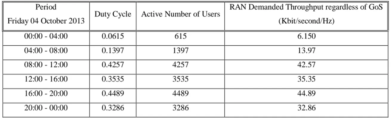
In this stage the RAN demanded throughput is determined based on two inputs, the average demanded throughput per user 10 (bit/s/Hz) and the duty cycle from the prescribed traffic profile. Table (2) provides the RAN demanded throughput using Eq. (12) for different duty cycle values which gives a percentage of the active users from a total number of users based on the traffic profile of Friday 04 October 2013Fig. 6.
Table 2.RAN Demanded Throughput
Period
Friday 04 October 2013 Duty Cycle Active Number of Users
RAN Demanded Throughput regardless of GoS (Kbit/second/Hz) 00:00 - 04:00 0.0615 615 6.150 04:00 - 08:00 0.1397 1397 13.97 08:00 - 12:00 0.4257 4257 42.57 12:00 - 16:00 0.3535 3535 35.35 16:00 - 20:00 0.4489 4489 44.89 20:00 - 00:00 0.3286 3286 32.86
4.2.3 Grade of Service
Generally, any approach to reduce the energy consumed by the RAN shouldn’t in any case degrade the GoS provided by the RAN to its users, hence: the offered throughput should always maintain its GoS according to Eq. (11). Therefore, the RAN offered throughput should always exceed the RAN demanded throughput by a factor of 0.3. Table (3) provides this updated information.
Table 3.RAN Demanded Throughput with Regard to GoS
Period Friday 04 October 2013
RAN Demanded Throughput with Regard to GoS (Kbit/second/Hz) 00:00 - 04:00 20.5 04:00 - 08:00 46.56 08:00 - 12:00 141.9 12:00 - 16:00 117.83 16:00 - 20:00 149.63 20:00 - 00:00 109.53
4.2.4 Energy Efficient Operation
At this stage having both the lookup table for the RAN offered throughput Fig. 10 and the RAN demanded throughput Table (3), choosing the energy efficient operation become a straight forward decision by means of switching (OFF/ON) RAN BSs to meet with the energy efficient operation decided by the model. Table (4) gives all the information needed to decide which operation to go to.
Table 4.Energy Efficient RAN Decision
Period Friday 04 October 2013
RAN Demanded Throughput with regard to GoS (Kbit/s/Hz)
RAN offered Throughput
(Kbit/s/Hz) RAN Operation
00:00 - 04:00 20.5 55.260 9 04:00 - 08:00 46.56 55.260 9 08:00 - 12:00 141.9 142.174 169 12:00 - 16:00 117.83 120.727 100 16:00 - 20:00 149.63 154.000 225 20:00 - 00:00 109.53 109.715 64
The criteria for deciding the energy efficient operation depend on choosing the closest higher RAN offered throughput compared to the RAN demanded throughput in a certain period. Table (4) provides the sufficient information needed to establish the decision stage of the process.
For example the RAN demanded throughput during the period 00:00 – 04:00 is 20.5[Kbit/s/Hz] and as shown in Table (4) the closest higher RAN offered throughput is 55.260 [Kbit/s/Hz] which provided by a RAN operation of 9 BSs, Therefore it is convenient and moreover more energy efficient decision to leave 9 BSs operating and switch OFF the rest with account to the RAN operation explained in Section (4.1.1) provided that the previous RAN operation was more than 9 BSs.
4.2.5 Energy Efficiency Evaluation
After applying the methodology described in Section 3 and with regard to Fig. 10, the ECR is calculated in order to quantify the reduction in energy consumption. As stated in Table (1) the transmitted power for a single BS is 40 dBm this corresponds to 10 Watt linear value. Therefore, using Eq. (8,9), Table (5) provides the ECR values for different periods of Friday 04 October 2013.
Table 5.ECR Values for Energy Efficient RAN
Period
Friday 04 October 2013 RAN operation
E Joule/second
RAN Offered Throughput (Kbit/second/Hz) ECR Joule/Kbit/Hz 00:00 - 04:00 9 90 55.260 1.63 04:00 - 08:00 9 90 55.260 1.63 08:00 - 12:00 169 1690 142.174 11.88 12:00 - 16:00 100 1000 120.727 8.28 16:00 – 20:00 225 2250 154.000 14.61 20:00 - 00:00 64 640 109.715 5.83
From Table (5) it is observed that the ECR is increasing with the offered throughput, however, the EER provides a better understanding of the energy utilization in RAN. As shown in Section 2 it gives an important insight of the energy utilization in a RAN since this metric evaluates the RAN
energy. Therefore, to evaluate the methodology performance the EER values for Friday 04 October 2013 when applying the proposed methodology were calculated and noted, the same calculation were made for the same day when applying a fully functioning RAN operation (256 BSs).
By calculating the EER for both the energy efficient RAN operation and fully functioning RAN operation a value of 0.023 (Kbit/Joule/Hz) EER were achieved using the proposed methodology while a value of 0.0115 (Kbit/Joule/Hz) EER were achieved for a fully RAN operation. The obtained results showed more energy utilization using the proposed methodology and the RAN is more energy efficient by a factor of 50 percent.
5 Conclusions
5.1 Concluding Remarks
The huge demand of higher data rates in mobile networks resulted in raising the concerns about energy consumption in RANs. Therefore, establishing a model that employs this tradeoff to efficiently reduce the energy consumption in RAN is a need.
In this thesis, the tradeoff between demanded throughput and energy consumption was studied and employed. A purpose-built algorithm with certain assumption was used to establish an energy efficient operational model that provides sufficient information regarding ECR for the RAN operators and moreover, evaluates the RAN performance from an EE point of view. This is done by means of switching OFF unutilized BSs. which indicate the huge amount of energy reduction in account for the amount of energy needed to operate a BS.
This thesis contributes in the area of cellular systems through its ability to be applied in many wireless systems. the assumption used throughout this thesis are quite general for any radio access based system and could be applied to many wireless systems other than LTE with account to different characteristics for different radio access technologies.
Furthermore, based on the proposed methodology in this thesis a reduction in energy consumption by 50 percent is achieved, this was done without degrading the RAN GoS and also with fully delivering the user traffic preferences. However, the RAN deployment proposed is not quiet realistic but it is important to mention that the whole proposed methodology is a basic framework which can adjusted according to different RAN scenarios and real radio access systems.
5.2 Recommendations for Future Work
This section provides suggestions for future research within the area where the thesis contributes. The energy consumption considered in this thesis was the energy used for signal transmission (power radiated from antenna).Therefore, it is recommended to study the concomitant reduction in the energy used to run the BS since the methodology used in this thesis is to switch OFF all unutilized BSs. Another recommendation is to investigate the spatial-traffic tradeoff which implies that a user experience different values of data rate inside its home BS. Studying this tradeoff is important to account for a more realistic users distribution and the user mobility factor.
Moreover, one of this thesis contributions is that the proposed methodology used to reduce and evaluate the energy consumption could be applied to various wireless systems, therefore, it is recommended to apply the proposed methodology to different communication standard with account
for their characteristics. This implies investigating small cells deployment approach as an example from an EE prospective.
References
[1] “Ericsson Mobility Report” Mobile World Congress, Tech. Rep., Feb. 2015.
[2] A. Fehske, G. Fettweis, J. Malmodin and G. Biczok, "The global footprint of mobile communications: The ecological and economic perspective," Communications Magazine, IEEE, vol. 49, pp. 55-62, 2011.
[3] S. Tombaz, A. Vastberg and J. Zander, "Energy- and cost-efficient ultra-high-capacity wireless access," Wireless Communications, IEEE, vol. 18, pp. 18-24, 2011.
[4] Ying Hou and D. I. Laurenson, "Energy efficiency of high QoS heterogeneous wireless communication network," in Vehicular Technology Conference Fall (VTC 2010-Fall), 2010 IEEE 72nd, 2010, pp. 1-5.
[5] D. Zeller, M. Olsson, O. Blume, A. Fehske, D. Ferling, W. Tomaselli, and I. Gódor,
"Sustainable Wireless Broadband Access to the Future Internet - The EARTH Project," in The Future Internet. Springer, 2013, pp. 249–271.
[6] G. Auer, V. Giannini, C. Desset, I. Godor, P. Skillermark, M. Olsson, M. A. Imran, D. Sabella, M. J. Gonzalez, O. Blume and A. Fehske, "How much energy is needed to run a wireless network?" Wireless Communications, IEEE, vol. 18, pp. 40-49, 2011.
[7] J. David, (2012) Optimizing Power Efficiency in mobile RAdioNETWorks (OPERA-Net)[Online]. Available FTP: Docbox.etsi.org
Directory:Workshop/2012/201206_EEWORKSHOP/06_RESEARCHFile: OPERA12_DAVID.pdf [8] Daquan Feng, Chenzi Jiang, Gubong Lim, L. J. Cimini Jr., Gang Feng and G. Y. Li, "A survey of
energy-efficient wireless communications," Communications Surveys & Tutorials, IEEE, vol. 15, pp. 167-178, 2013.
[9] I. Humar, Xiaohu Ge, Lin Xiang, Minho Jo, Min Chen and Jing Zhang, "Rethinking energy efficiency models of cellular networks with embodied energy," Network, IEEE, vol. 25, pp. 40-49, 2011.
[10] Y. Chen, S. Zhang, S. Xu and G. Li, "Fundamental trade-offs on green wireless networks," Communications Magazine, IEEE, vol. 49, pp. 30-37, 2011.
[11] M. Hatay, "Empirical formula for propagation loss in land mobile radio services," Vehicular Technology, IEEE Transactions on, vol. 29, pp. 317-325, 1980.
[12] “Evolved universal terrestrial radio access (E-UTRA); Further advancements for E-UTRA physical layer aspects, (Release 09),” 3GPP Standard: 3GPP TR 36.814, pp. 93-96, Mar 2010.
[13] S. Y. Seidel and T. S. Rappaport, "914 MHz path loss prediction models for indoor wireless communications in multifloored buildings," Antennas and Propagation, IEEE Transactions on, vol. 40, pp. 207-217, 1992.
[14] C. E. Shannon, "Communication In The Presence Of Noise," Proceedings of the IEEE, vol. 86, pp. 447-457, 1998.
[15] J. G. Andrews, "Interference cancellation for cellular systems: a contemporary overview," Wireless Communications, IEEE, vol. 12, pp. 19-29, 2005.
[16] ECR, "Network and telecom equipment - energy and performance assessment test procedure and measurement methodology," Tech. Rep. Draft 3.0.1, ECR initiative, Deutsche Telekom AG, Germany, 2010.
[17] B. Badic, T. O'Farrrell, P. Loskot and J. He, "Energy efficient radio access architectures for green radio: Large versus small cell size deployment," in Vehicular Technology Conference Fall (VTC 2009-Fall), 2009 IEEE 70th, 2009, pp. 1-5.
[18] ETSI, "Energy efficiency of wireless access network equipment," ETSI Environmental Engineering Standard DTS/EE-00007 V1.1.1, ATIS, 2009.
[19] M. Hamid, N. Björsell and S. Ben Slimane, "Empirical Statistical Model for LTE Downlink Channel Occupancy", p. 9, 2015.
Appendix A
Traffic Model
A RAN operation of 9 BSs is generated along with the users distribution after that the traffic model is applied to the generated RAN operation, thereafter, the throughput per user is calculated as shown in processes (2) and (4).
RAN Operation and Users Distribution %%%%%%%%% Notations%%%%%%%%%
%RAN_area = RAN Deployment Area 5km^2 %RAN_op = RAN Operation (Number of BSs) %BS_Loc = BSs Coordinates
%users_loc =Users Coordinates RAN_area = 5e6;
load us_loc1%Predefined uniform distributed vector
load us_loc2%Predefined uniform distributed vector
RAN_op =9 ; %Can choose different
%%%%%%%%%% RAN Deployment - BSs Coordinations
BS_cor = linspace(sqrt(RAN_area)/8,sqrt(RAN_area),ceil(sqrt(RAN_op)));
for ii = 1:ceil(sqrt(RAN_op))
for jj = 1:ceil(sqrt(RAN_op))
BS_Loc(ii,jj) = BS_cor(ii) + 1j*BS_cor(jj);
end end
BS_Loc=BS_Loc(:);
%%%%%%%%%% RAN Operation Plot figure(1) for ii = 1:(ceil(sqrt(RAN_op)))^2 circle(real(BS_Loc(ii)),imag(BS_Loc(ii)),0.7*(BS_Loc(2)-BS_Loc(1))) hold on end r1=sqrt(RAN_area)/8+sqrt(RAN_area);
plot(BS_Loc,'or','linewidth',2)
hold on
%%%%%%%%%% RAN Users Distribution + Plot users_loc = (r1)*x+(r1)*1j*y;
As shown in the Figure the RAN operation and users distribution were plotted under the assumption stated in Section 3.
SIR and Throughput per User Calculation
In this part using the calculated distances vectors the SIR is determined using the traffic model explained in Section 3 in order to determine the offered throughput per user as shown in Section 2 %%%%%%%%% Notations%%%%%%%%%
%dis_inter= Distance Between Users and Interfering BSs Vector %dis_sig= Distance Between User and Worst Case BS Vector (home BS)
%lognormal= Lognormally Distributed Vector with zero mean and Standard Deviation 7 dB to apply shadowing
%PLs= Propagation Loss for Received Signal (home BS)
%PLi= Propagation Loss for Received Interference (other BSs) %x= Mean Value of PLs
%y= Mean Value of PLi %xx= Apply Shadowing for x %yx= Apply Shadowing for y %S= Received Signal Power in dB %I= Received Interference Power in dB
%Slin =Received Signal Power in Linear Scale
%Ilin = Received Interference Power in Linear Scale %SIR = Signal to Interference Ratio
%c = Capacity per User in [bit/s/Hz] %%%%%%%%%%%%%%%%%%%%%%%%%%%%
load dis_inter9%gives ll
load dis_sig9%gives gg
load lognormal%gives n
%%%%%%%%%%% Calculate PLs & PLi according to Eq.(4) PLs=36.7*log10(gg)+26*log10(2.6)+5+42.7;
PLi=36.7*log10(ll)+26*log10(2.6)+5+42.7;
%%%%%%%%%%% Apply Shadowing to the Mean Values of PLs & PLi x=mean(PLs);
y=mean(PLi); xx=x+7*n; yx=y+7*n;
%%%%%%%%%%% Calculate S & I according to Eq.(1) S=40-xx;
I=40-yx;
Slin=db2pow(S); Ilin=db2pow(I);
%%%%%%%%%%% Calculate c according to Eq.(1) kk=1; for dd=1:1000 SIR(dd,kk)=Slin(dd,kk)/Ilin(dd,kk); end cap=[]; c=mean(1*log2(1+SIR)) c = 5.5260