Migration of a Mobile Core Application to a
Simplified Infrastructure
In-Service Performance Analysis
Priyanki Vashi
Master’s Thesis at School of Innovation Design and Technology
Mälardalen University Västerås, Sweden
PRIYANKI VASHI Master Thesis
Technical mentors at Ericsson: Leif Y. Johansson, Nikhil Tikekar Industrial mentors at Ericsson: Niklas Waldemar
Academic mentors at MDH: Thomas Nolte and Damir Isovic Academic study advisor at MDH: Damir Isovic
Registration number:
©2012 PRIYANKI VASHI
Master’s Thesis at Ericsson (within Evolved Infrastructure PST group) in cooper-ation with the School of Innovcooper-ation Design and Technology
Mälardalen University Box 883, 721 23 Västerås info@mdh.se, Sweden
i
Abstract
Ericsson has always strived for the technology leadership in its offering by designing products based on the latest technology. Going ahead with a similar thought it started exploring an idea of running a mobile core application using a Simplified Infrastructure (SI) to eventually enable the Cloud based solutions. But in order to run these type of applications in the Cloud, the in-service performance provided by such a SI should be the same as the native infrastructure in order to maintain the mobile core application’s QoS. "High availability" of the infrastructure is one of the measure of the ISP and from the ISP point of view, such a migration would be considered feasible only if the SI is able to maintain the same level of availability as provided by the native infrastructure solution without bringing in any major architecture changes within the SI. Hence this master thesis project investigates the feasibility of achieving the same availability as before if the mobile core application is to be migrated from the native infrastructure to the SI. Such a feasibility exploration was the very first attempt with respect to the SI within Ericsson, which was executed through this master thesis project. In order to achieve the goal of this thesis project a detailed system study was carried out, which focused on the native infrastructure architecture, how it was maintaining the "high availability" and how it differed from the SI.
In the end, it was possible to confirm that the level of availability of infrastructure services as provided through the SI will be higher than the native infrastructure after the migration if the proposed suggestions of this master thesis project are implemented successfully. These implementations also do not change the architecture of the SI in any major way. The end results of this thesis project were also highly appreciated by Ericsson and are now part of the development plan for next mobile core infrastructure solution at Ericsson.
Acknowledgements
The memories associated with this master thesis work will always have a special place in my heart and to have such an amazing feeling about my involvement in the work, I would like to start with thanking my Ericsson mentors and technical supervisors Leif Johansson, Nikhil Tikekar and Niklas Waldemar. Without their belief and trust in my capabilities it would not have been possible to reach an expected outcome. In addition, I would also like to thank the designers, system managers and previous master thesis students (Isaac and Manuel) at Ericsson, who provided me a valuable information, which was not so evident in an available documentation in order to reach an expected outcome of this thesis project. Some of the learnings, which I really want to highlight here is, first why to bring a simplification and then secondly how to bring the simplification in a more systematic way for a complex products such as the one studied as a part of this thesis project. Well in this case, the simplification is mainly driven to enable the compatibility with the latest technology involving the Multicores, Virtualization and hence Cloud Computing and then leverage the benefits of the Cloud technology. Not only technically it was rewarding for me to work in this area but also motivating and an inspiring experience to interact with such a simple minded and humble but yet very talented people of Ericsson.
I would also like to equally thank professor Thomas Nolte for all his support and clear guidelines on my queries during this thesis work. I would honestly admit that I felt very happy and honoured when Thomas had agreed to be my thesis supervisor just based on an initial phone talk without even meeting me in person. Interacting with him was a great experience. I am also very grateful to professor Damir Isovic for encouraging me throughout my master’s education as my study advisor. Both of them have always answered my questions precisely and provided me with a very valuable feedback and suggestions.
Last but not the least, I would also like to convey my deepest regards and sincere thanks to my family and more specifically to my mother, Kantaben Vashi and best friend, Ravikumar Darepalli, who is also my life partner. Their words were constant source of encouragement throughout my Life and sharing the Master’s Education experience with them is none different than that !
Contents
Contents III
List of Figures V
List of Tables VI
List of Acronyms and Abbreviations VII
1 Introduction 1 1.1. Overview . . . 1 1.2. Related Work . . . 5 1.3. Problem Description . . . 9 1.4. Goals . . . 10 1.5. Methodology . . . 11 1.6. Scope . . . 14 1.7. Limitations . . . 15 1.8. Target Audience . . . 15 1.9. Thesis Outline . . . 16 2 General Background 17 2.1. Ericsson MSC Server Blade Cluster (MSC-S BC) . . . 17
2.1.1. Overview . . . 17
2.1.2. MSC-S BC Hardware Architecture . . . 19
2.1.3. MSC-S BC Software Architecture . . . 22
2.1.4. MSC-S BC blade states for MSC-S BC . . . 25
2.1.5. MSC-S BC Hardware Management . . . 26
2.1.6. Link and Plane Handling for MSC-S BC . . . 28
2.1.7. MSC-S BC Functional View . . . 30
2.2. In-Service Performance (ISP) . . . 32
2.2.1. ISP Overview . . . 32
2.2.2. Availability Measurements . . . 33
2.3. SI Prototype Summary . . . 34
2.3.1. Overview . . . 34
2.3.2. Verification Environment in Prototype . . . 37 iii
3 Evaluation 41
3.1. Approach for Theoretical Study . . . 41
3.1.1. Analysis from ISP Perspective . . . 41
3.1.2. Current System Design Perspective . . . 43
3.2. Theoretical Study Findings . . . 45
3.2.1. Interfaces Identified . . . 46
3.2.2. List of Functions using NON-IP Interfaces . . . 46
3.3. Analysis of Unavailability of Identified Functions . . . 46
3.3.1. Function-1: Automatic Boot . . . 46
3.3.2. Function-2: Supervision of Suspected Faulty Blade . . . 48
3.3.3. Function-3: Link Fault Detection and Recovery . . . 50
3.3.4. Function-4: Plane Fault Detection and Recovery . . . 51
3.3.5. Remaining functions: Function-5 to Function-10 . . . 53
3.3.6. Summary on Proposals for Different Functions . . . 53
3.4. Verification of Proposals using Prototype . . . 54
3.4.1. Verification Strategy . . . 54
3.4.2. Test Case Description . . . 55
3.4.3. Test Execution . . . 56
4 Conclusions and Future Work 63 4.1. Conclusions . . . 63
4.1.1. System Study . . . 63
4.1.2. Laboratory Tests . . . 64
4.2. Future Work . . . 64
Bibliography 67 A Mobile Network Architectures 71 A.1. Mobile Network Architecture . . . 71
A.1.1. Global System for Mobile Communication (GSM) . . . 71
List of Figures
1.1. UMTS network topology. . . 2
1.2. Different phases of developement of Simplified Infrastructure idea. . . . 4
1.3. Ericsson MSC-S Blade Cluster view at blade level. . . 6
1.4. Ericsson MSC-S hybrid cluster topology (1st variant of SI prototype). . 7
1.5. Ericsson MSC-S external cluster topology (2nd variant of SI prototype). 8 1.6. Ericsson MSC-S split cluster topology (3rd variant of SI prototype). . . 9
1.7. Step-1 and Step-2 of used methodology. . . 13
1.8. Step 3,4 and 5 of used methodology. . . 14
2.1. MSC-S Blade Cluster rack view. . . 18
2.2. MSC-S Blade Cluster view at blade level. . . 19
2.3. MSC-S Blade Cluster hardware architecture. . . 20
2.4. MSC-S BC layered architecture. . . 23
2.5. BSOM signal flow diagram between MSC-S blades and SIS blade. . . 27
2.6. IS Links supervisions. . . 28
2.7. ISP Measurements. . . 33
2.8. Generic view of the Simplified Infrastructure (SI). . . 35
2.9. Ericsson MSC-S external cluster topology. . . 36
2.10. The Stockholm Laboratory B network topology. . . 39
3.1. BSOM signal flow diagram between MSC blades and a SIS blade. . . 44
3.2. Connectivity between CP Blades and Infrastructure Blades. . . 45
3.3. Analysis of unavailability of automatic boot function. . . 47
3.4. Analysis of an unavailability of the MSC-S BC blade supervision function. 49 3.5. Analysis of an unavailability of link management function. . . 51
3.6. Analysis of unavailability of plane handling function. . . 52
3.7. Analysis of unavailability for rest of the functions. . . 53
3.8. Summary of the proposed alternatives. . . 54
A.1. GSM network topology. . . 72
A.2. UMTS network topology. . . 75
1.1. Global Mobile Data Traffic Growth . . . 3
2.1. Bridge machine’s features. . . 37
2.2. Cloud machine’s features. . . 38
2.3. Stockholm Laboratory B machines’ features. . . 38
3.1. Compilation of tests results where one of the prototype MSC-S BC blade was added to an existing MSC-S BC cluster. . . 57
3.2. Compilation of tests results where one of the prototype MSC-S BC blade was removed from an existing MSC-S BC cluster. . . 58
List of Acronyms and Abbreviations
3GPP Third Generation Partnership Project
API Application Programming Interface
APG Adjunct Processor Group
AUC Authentication Center
BSC Base Station Controller
BSS Base Station System
BTS Base Transceiver Station
BW Bandwidth
CAPEX Capital Expenditure
CPU Central Processing Unit
CS Circuit-Switched
CSCF Call Session Control Function
EIR Equipment Identity Register
eNB Evolved Node B
EPC Evolve Packet Core
ETSI European Telecommunications Standard Institute
GB Gigabyte
Gbps Gigabits per second
GHz Gigahertz
GPRS General Packet Radio Service
GSM Global System for Mobile communications
GUI Graphical User Interface
HLR Home Location Register
HSS Home Subscriber Server
IaaS Infrastructure as a Service
IEEE Institute of Electrical and Electronic Engineers
IMS IP Multimedia Subsystem
IMSI International Mobile Subscriber Identity
I/O Input/Output
IP Internet Protocol
ISO International Standard Organization
ISP In-service Performance
IT Information Technology
KVM Kernel-based Virtual Machine
LAN Local Area Network
LTE Long Term Evolution
MAC Media Access Control
MB Megabyte
Mbps Megabits per second
MGW Media Gateway
MIPS Million Instructions Per Second
ms milisecond
MSC Mobile services Switching Center
MSC-S Mobile Switching Center Server MSC-S BC MSC-S Blade Cluster
MSISDN Mobile Station Integrated Services Digital Network
NGN Next Generation Network
ix
NMC Network Management Center
NMS Network Management Subsystem
NSS Network Switching Subsystem
OMC Operation and Maintenance Center
OPEX Operational Expenditure
OS Operating System
OSI Open Systems Interconnection
OSS Operation Support System
PaaS Platform as a Service
PC Personal Computer
PS Packet-Switched
PSTN Public Switched Telephone Network
QoE Quality of Experience
QoS Quality of Service
RAM Random Access Memory
RAN Radio Access Network
RNC Radio Network Controller
SI Simplified Infrastructure
SIM Subscriber Identity Module
SIS Site Infrastructure Support
SMS Short Message Service
SPX Signaling Proxy
SSH Secure Shell
UDP User Datagram Protocol
UPS Uninterruptible Power Supply
UMTS Universal Mobile Telecommunications System
VLAN Virtual Local Area Network
VLR Visitor Location Register
VM Virtual Machine
Chapter 1
Introduction
The aim of this chapter is to introduce the wider group of readers with the work carried out in this master thesis project. As a first step, an overview of the subject and it’s related work is described so that the readers can connect and follow the rest of the parts easily and logically. After that the problems, which had triggered this kind of work/study is described followed by a statement of the goals. Next, the methodology that is used to solve the identified problems is decsribed. Thereafter scope, limitations and the target audience of the project are clearly stated. Finally, an outline of the thesis is presented to highlight the structure of the thesis.
1.1.
Overview
Today Global System for Mobile Communications (GSM) and Universal Mobile Telecommunications System (UMTS)) are two of the most widely used mobile core network architectures. GSM represents a second generation (2G) digital mobile network architecture [1] and UMTS is a third generation (3G) mobile cellular technology standard [2]. On high level both the architecture topology is composed of three subsystems. The mobile core application (MSC-S application) and it’s infrastructure (Ericsson MSC-S Blade Cluster), which is focus of this master thesis project are part of one of the subsystem common to both the types of architectures. This subsystem is Network Switching Subsystem (NSS) and it is indicated as Switched Core Network subsystem in UMTS network topology using Figure 1.1. The NSS is composed of units like Mobile Switching Center Server (MSC-S), Home Location Register (HLR), Visitor Location Register (VLR) etc. so that different functions of this subsystem could be realized by different functional entities in the network [3]. Typically, a MSC-S node is responsible for the setup, supervision, and release of calls as well as for handling SMSs and managing terminals’ mobility. It also collects call billing data in order to send it to the Billing Gateway, which processes this data to generate bills for the subscribers.
Figure 1.1. UMTS network topology.
In the domain of mobile core network, Ericsson has succeeded to provide an efficient network solution by integrating a cluster based distributed system as one of the core infrastructure component for running Mobile Switching Center Server (MSC-S) and Home Location Register (HLR). Use of this cluster based distributed system added a huge amount of capacity and also made the network highly scalable and simple to operate with higher in-service performance. Not just in the domain of mobile core network solutions but in general, Ericsson has always strived to be the technology leader, while maintaining the ease of use with respect to it’s products and services. At the same time Ericsson as a vendor of telecom network provider also want to fulfil the growing demands of it’s large customer base, who in the near future wish to have a reduction in their capital expenditure (CAPEX) and an operational expenditure (OPEX) with respect to the new network installations as well as for the existing network expansion without compormising on any of the services, as provided in terms of scalability, ease of use and more significantly the in-service performance.
CAPEX is the capital expenditure, which is an initial investment needed to install the network (for both the HW and SW components) and OPEX is an operational expenditure, which is a running cost of maintaining and expanding the network (again both the HW and SW components). And the motivation from the telecom operators to put forward such demands is to be able to cater the growing needs of their end users with respect to the telephony, high speed Internet access, Multimedia Message Service (MMS) and Short Message Service
1.1. OVERVIEW 3
(SMS) with as optimal cost as possible. Since the end users also expect the same Quality of Experience (QoE) as they obtain while using wired devices [4] for some of these services, this in turn puts high demand on the network performance while deliverying these services thorugh the mobile networks. Additionally in the given case expansion of the mobile network is directly proportional to the growing demands of such services and it is very dynamic. Hence the CAPEX and the OPEX required to build and sustain such a deployment is becoming a major concern for the telecom operators [5].
Furthermore the demands in terms of bandwidths are also increasing [6] (as it can be seen from Table 1.1) especially due to the emergence of new services and applications requiring Internet access [7]. Therefore developing a flexible, cost optimal and future proof network solution is a challenging task. Currently the solutions to boost the mobile network’s bandwidth are being addressed by the Long Term Evolution/Evolved Packet Core architecture (LTE/EPC) [8] [9]. LTE introduces the sophisticated radio-communication techniques enabling faster and more efficient access networks while EPC involves the deployment of a packet-based core network capable of dealing with the future traffic increases [10]. Additionally the IP Multimedia Subsystem (IMS) [11] [12] [13] is the main framework to provide the voice and SMS services over IP. Hence exploring Cloud Computing technology for hosting various telecommunication applications could be very futureproof and worth of efforts [14].
Table 1.1. Global Mobile Data Traffic Growth
Year Annual Increment
2009 140% 2010 159% 2011 (expected) 133% 2012 (expected) 110% 2013 (expected) 90% 2014 (expected) 78%
According to the National Institute of Standards and Technology (NIST) [15] Cloud computing is, "a model for enabling ubiquitous, convenient, on-demand network access to a shared pool of configurable computing resources (e.g., networks, servers, storage, applications, and services) that can be rapidly provisioned and released with minimal management effort or service provider interaction". Data warehousing, computing as a service, and virtual data centers are just a few examples of the cloud services. But let’s not forget that the telecom applications demand a high Quality of Service (QoS). This means high QoS requirements still needs to be satisfied even while running these applications with the cloud based infrastructure.
To acheive this, as a first step Simplified Infrastructure (SI) prototype was built at Ericsson (which eventually enables the migration of telecom applications to the Cloud) considering the important applications of the mobile core network (MSC-S and HLR). The complete activity was divided into three phases as indicated in Figure 1.2. The first two phases of the Simplified Infrastructure mainly focussed on the design of different variants of the SI prototype, which is related work for this master thesis project and it is described as a part of the related work in Section 1.2. It is important to note that the successful implementation of the SI prototype previous to this project work played a very crucial role during the verification phase of the current master thesis project and without such a prototype in place, it would not have been possible to practically demonstarte the end results of the current master thesis project.
Figure 1.2. Different phases of developement of Simplified Infrastructure idea.
The study done as a part of current master thesis, which represents the third and final phase, is mainly focussing on an analysis of "high availability" criteria with respect to the proposed SI solution. The method used during this study makes a
1.2. RELATED WORK 5
very good logic and absolute clarity on what actions need to be taken in order to achieve the same or better level of availability if a mobile core application to be migrated from an Ericsson native infrastructure (MSC-S BC) to SI, and eventually to the Cloud.
Using the end results obtained from the current master thesis project, it is possible to say that there is a huge potential for hosting this type of mobile core applications using SI with the improved level of availability. This proof of concept would eventually help to secure the higher level of availability while migrating to the Cloud as well. Of course, all the drawbacks that use of public Internet may introduce when providing these services must be kept in mind (Oredope and Liotta also regarded this as an important concern in [16]).
1.2.
Related Work
During first two phases of the study, the SI prototype was designed [17]. Three different variants of the SI prototype were explored and all of the variants were built by virtualizing the cluster based distributed system, which was considered one of the most successful core infrastructure platform within Ericsson and it is communicating over IP based connectivity with the rest of the components within SI. In Ericsson’s terms, this core infrastructure platform is named as "Ericsson Blade Clutster" and when MSC-S application is run on this platform, it would be identified as "MSC-S BC" (Figure 1.3). The different variants of the SI included following types. The purpose with each of the prototype variant is also presented further.
• Hybrid Ericsson MSC-S BC topology (1st variant of SI protoype)
• Ericsson MSC-S external cluster topology (2nd variant of SI protoype)
Figure 1.3. Ericsson MSC-S Blade Cluster view at blade level.
Hybrid Ericsson MSC-S BC topology:1st variant The purpose of this
de-sign was to demonstrate the correct operation of the system when placing a prototype MSC-S blade in an emulated Cloud environment (outside the racked architecture). Figure 1.4 depicts this topology of an Ericsson MSC-S hybrid blade cluster, where a prototype MSC-S blade is implemented on an external server located outside the rack.
1.2. RELATED WORK 7
Figure 1.4. Ericsson MSC-S hybrid cluster topology (1st variant of SI prototype).
Ericsson MSC-S external cluster topology:2nd variant The external
clus-ter topology is represented in Figure 1.5. This prototype design consisted of an Ericsson MSC-S BC implementation whose only MSC-S blades are prototype MSC-S blades located in a emulated Cloud environment. The purpose with this prototype variant was to verify the correct operation of the cluster protocols in presence of network impairments as well as the system’s stability with this network configuration.
Figure 1.5. Ericsson MSC-S external cluster topology (2nd variant of SI prototype).
Geographically split Ericsson MSC-S BC topology:3rd variant Figure 1.6
illustrates the Ericsson MSC-S split cluster topology. Geographically split cluster configuration consisted of an Ericsson MSC-S BC implementation whose only MSC-S blades are prototype MSC-S blades located in several geographically remote emulated Cloud computing environments. The purpose with this prototype variant was to verify the correct operation of the cluster protocols in presence of this combination of network impairments in the system, as well as the system’s stability with this network configuration.
1.3. PROBLEM DESCRIPTION 9
Figure 1.6. Ericsson MSC-S split cluster topology (3rd variant of SI prototype).
The tests results from all the three variants of the SI prototype had succeded to show the practical demonstation of running one of the mobile core applications, in this case MSC-S on SI. More details about each of the variants and their respective tests could be found here [17].
1.3.
Problem Description
As mentioned earlier, in order to solve large CAPEX and OPEX problems of telecom operators, one of the possible directions to go is to leverage the Cloud based model for providing telecom services and maintaining the same QoS as before. From Ericsson’s point of view, before guranting the same QoS in the Cloud environment, there are a number of problems which needs to be solved and the main problem that this thesis project deals with (and to which a solution is provided) are:
• Problem-1: How to efficiently use the existing core infrastructure component while migrating to the new technology including Cloud (applicable for both the HW and SW components) - As mentioned earlier, in the domain of mobile core
networks, Ericsson has succeeded to provide a scalable, easy to operate and higher capacity network solution by introducing a cluster based distributed system, which forms one of the core infrastructure components in the core network solution. This also means that over the period Ericsson had spent huge amount of time and R&D efforts to develop such a solution and as a next step it is natural to explore an efficient use of this particular infrastructure component, while migrating to the new technology like the Cloud. This will add a value to the operational efficiency and hence reduce the time to market (TTM) while migrating to any new technology. If TTM is reduced then this would also mean better business efficiency.
• Problem-2: How to identify the limiting factors in the current cluster based distributed system, which might prevent it to migrate to SI while maintaining the same level of availability before and after the migration - To make an efficient use of the cluster based distributed system, it was necessary to understand limitations, which might impact it’s availability after migrating to SI since in principle, SI would only support pure IP based connectivity. Hence interfaces and functions using NON-IP interfaces (even though contributing to maintain the availability in the native solution) in the native infrastructure environment can not be supported. Also another such limitation to solve was to decouple the HW and SW components as much as possible without bringing in major architectural changes. Next to solve was the ambiguity on the usage of IP based and NON-IP based interfaces and associated functions connected to the in-service performance due to the lack of sufficient internal system documentation.
• Problem-3: How to gurantee the same level of availability (part of in-service performance) while migrating the mobile core applications to the proposed SI from the native infrastructure - The solution of SI is proposed to address the problems stated above, however, when this project was proposed in April-2012, SI had not yet been analyzed and verified against the "high availability" criteria connected to its’ in-service performanance that these applications require in terms of QoS. Therefore a detailed study and thorough testing using a prototype became mandatory to conclude the previously proposed SI solution.
1.4.
Goals
The main goal of this master thesis project was to study the feasibility of migration of one of the mobile core application from the native infrastructure to the Simplified Infrastructure to enable the Cloud based solutions. Such a migration would be considered feasible only if the Simplified Infrastructure is able to maintain the same level of the availability as provided by the native infrastructure
1.5. METHODOLOGY 11
solution without bringining in any major architecture changes within the Simplified Infrastructure.
Before explaining detailed goals of this thesis project, it is necessary to elaborate on the meaning of important terms. In the given context,
• In-service performance defines the measure of availability, which is measured using the in-service performance statistics collected internally within Ericsson. • Cloud based solutions here represents geographically separated resources -In the current project it represents a group of virtual blades running as a distributed cluster with only IP based connectivity. This configuration is equivalent to a distributed cluster formed by physical blades running within the native infrastructure. In this case there exist two variants, one is called Integrated Site (IS) and the other is Ericsson Blade System (EBS).
The main goal is divided into three subgoals as presented below.
Goal-1: Study the architecture of the native infrastructure, understand how it was
maintaining the high availability and how it differs in maintaining the high availability compare to the Simplified Infrastructure.
Goal-2: Based on the identified differences between two infrastructure solutions
analyze if there is a way to propose a solution so that the same level of availability can be achieved before and after the migration without bringing in major architecture changes within the Simplified Infrastructure.
Goal-3: If there is a suitable solution, conduct various tests using the existing
Simplified Infrastructure prototype to practically demonstarte the proposed solution works as expected and hence help to provide a concrete conclusion on the feasibility of this migration.
1.5.
Methodology
In order to fulfill the goals of this thesis project, a qualitative approach was utilized. Secondary research was used as a qualitative method, which also includes understanding of the work done as a part of the previous studies. Moreover, this research provided material for the background chapter and allowed to obtain a full state-of-the-art overview of the subject. This literature review also provided a solid foundation upon which various ideas for different proposals are built.
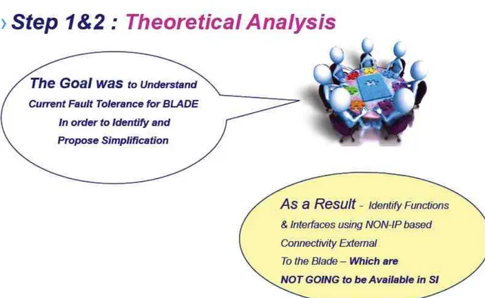
• Step-1: As a first step, a study to be done in order to understand what defines the in-service performance and what kind of data is available as a part of
the in-service performance statistics internal to Ericsson in co-operation with Ericsson’s system managers. Next was to identify which type of functionality is crucial and currently playing an important role in maintaining the required level of in-service performance with respect to these mobile core applications so that the focus area for the study in Step-2 could be identified. An expected output from this step was to prepare a detailed report indicating different types of available ISP statistics.
• Step-2: As a second step, another study is to be carried out focussing on the functional areas that were identified from Step-1. This was required in order to understand the limiting factors of this core component preventing it to migrate to the Simplified Infrastructure with the required ISP. While doing an analysis of identified functional areas, this study should also have a focus to decouple the HW and the SW components from each other. An expected outcome from this step was to identify limiting interfaces and functions of the platform under consideration. During the identification prcocess, apart from reviewing available system documentation, a thorough discussions with the Ericsson designers and System Managers was to be carried out (mainly due to the lack of required system documentation and also while bringing in such changes where the technique was to bring simplification by removing the interfaces and functions it becomes crucial to understand the thought process behind the existing design).
1.5. METHODOLOGY 13
Figure 1.7. Step-1 and Step-2 of used methodology.
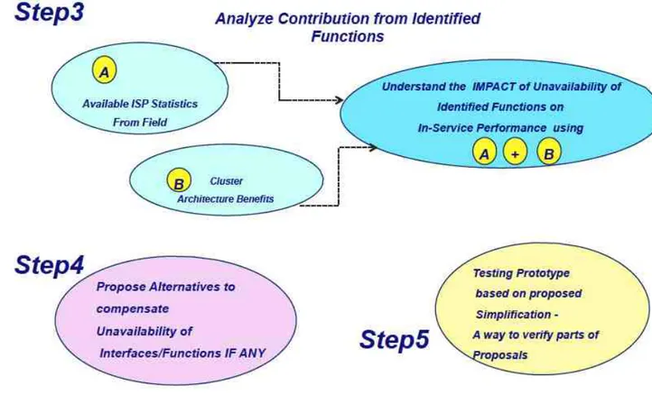
• Step-3: As a third step, all the identified functions to be analyzed based on the two quality inputs. One of the inputs is to be derived from the Step-1 study results and the another input is to be derived based upon benefits of the cluster based distributed system. The results to be used from Step-1 are mainly related to the functionality, which directly affect the availability of this core component.
• Step-4: As a fourth step, an appropriate alternative is to be proposed for all the identified functions in Step-2 using the analysis done in Step-3 in order to gurantee the same or better level of the in-service performance that could be achieved after migration to the SI/Cloud.
• Step-5: As a last and fifth step, practically demonstrate (using the prototype) that if the proposed alternatives are implemented then the unavailability of identified functions could be compensated due to these alternatives to an
extent, which is acceptable to conclude that the platform under consideration will have the same level of in-service performance with this proposed Simplified Infrastructure.
Steps 3,4 and 5 are shown graphically in Figure 1.8.
Figure 1.8. Step 3,4 and 5 of used methodology.
1.6.
Scope
• Within Ericsson, there exist different variants of the processor and infrastruc-ture blades. A certain combination of the processor and the infrastrucinfrastruc-ture blades together form one of the core infrastructure components within a core network solution. As part of this thesis project, one such variant (IS based Blade Cluster) was studied, and the mobile core application considered was MSC-S.
1.7. LIMITATIONS 15
• A similar study would be required to carry out for the other variants of processor and infrastructure blades such as EBS (Ericsson Blade System), but the method used in this master’s thesis could be equally efficient for that as well.
• The practical experiment was carried out using a Ericsson proprietary MSC application prototype with limited functionality. In the future further studies should be conducted to verify the correct behaviour of a completely functional Ericsson MSC-S BC application as well as the other (related) applications to see if the results of this study can be generalized to the other (similar) applications.
• Study of certain software component, (even though they are part of the chosen variant) was out of the scope of this master’s thesis. One such software component is the IP Stack designed by Telebit (TIP stack).
• Troubleshooting of the prototyping problems was also decided to be kept outside the scope of this thesis work.
1.7.
Limitations
One of the main limitation in this thesis work was the use of a simulated environment during the verification phase.
During the last step, which was focusing on verification of the proposed alternatives, the GSM and UMTS type of mobile calls were generated using a simulated environment. However, since the main goal of this thesis was to demonstrate that the proposed idea works (as a proof of concept), a simulated environment was enough to carry out this initial verification.
1.8.
Target Audience
The primary audience of this work is the Ericsson’s internal design and systems group within Evolved infrastructure. The idea here was to show that the proposed methodology and derived results as one approach in order to simplify such a complex platform without impacting it’s in-service performance. Through such an approach it would be possible to have an open discussion on the proposed alternatives.
Another important target audience is Ericsson’s customers, who wish to leverage the benefits of the cloud technology with respect to their current mobile core network solution.
In addition to these readers, a specific group of researchers is interested in acquiring the knowledge with respect to a telecom network performance in the
Cloud, such as the one studied in this thesis project can also take the advantage of the described metodology.
1.9.
Thesis Outline
The thesis is structured in a linear manner, where the earlier chapters provide a general overview of the subjects necessary to understand the remaining chapters of the thesis. It is strongly recommended that the reader should thoroughly study the introdcution and the background chapters in order to provide an appropiate context for the subsequent experimental work.
Chapter 1 provides an introduction to the thesis. Chapter 2 provides related background information. Chapter 3 describes an evaluation part of this thesis work, which talks about the theoretical study findings and various conclusions of the findings. It also discusses details about the prototype, the verification strategy and the test cases used for verifying the findings of this theoretical study. Chapter 4 presents final conclusions and suggested future work. Appendix A explains a brief architecture of different types of mobile core networks (GSM and UMTS introduction). Appendix B (confidential) is a manual to configure a prototype testing environment used during this thesis work.
Chapter 2
General Background
The purpose of this chapter is to give a brief overview of the technologies and concepts involved in this thesis project so that the readers can easily understand/visualize how the work has been carried out. In addition the information provided here focuses only on the important areas of the subject, which are directly related to this project without going into unnecessary details.
Since the purpose of this thesis project was to analyze whether one of the crucial infrastructure components of a mobile core network could be migrated to a Simplified Infrastructure without any impact on it’s in-service performance, therefore at the begining of the chapter important concepts of the MSC-S BC architecture are described. The architecture includes both the HW and SW components description (Section 2.1). Next the important concepts, definitions and terminologies with respect to the in-service performance of the platform (Section 2.2) are described. In the end a theoretical description of the Ericsson’s MSC-S BC prototype and test environment (Section 2.3) is presented.
2.1.
Ericsson MSC Server Blade Cluster (MSC-S BC)
2.1.1. OverviewThe Ericsson Mobile Switching Center Server (MSC-S) [18] forms one of the important components within the Ericsson’s Mobile Softswitch solution [19]. Important functions of this server includes, set up and releases of end-to-end calls, handling mobility and hand-over of the calls between dfferent mobiles, the call charging etc. However recently it has been replaced by a more sophistacated state-of-the-art solution, called the MSC-S Blade Cluster (MSC-S BC). MSC-S BC is designed on the principle of a cluster based distributed system.
All the components of the Ericsson MSC-S BC are implemented as a racked architecture. As a part of this racked type of architecture, MSC-S BC can have
either one or two cabinets depending upon the capacity requirements it needs to serve. The first cabinet hosts all the mandatory components, while the second cabinet gives provision for an optional expansion of the components for supporting additional capacity. Pictorially Figure 2.1 presents the racked view of MSC-S BC where as Figure 2.2 gives a more detailed view of the same at blade level, where BC0 represents the mandaory cabinet and BC1 is the optional one.
2.1. ERICSSON MSC SERVER BLADE CLUSTER (MSC-S BC) 19
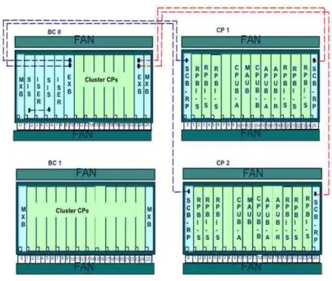
Figure 2.2. MSC-S Blade Cluster view at blade level.
In the MSC-S BC, the MSC-S’s functionality is implemented on several Generic Ericsson Processors (GEP). The generic term for such a GEP is "blade". Detailed descriptions for the functionality of different types of the blade is presented further as a part of the hardware architecture in Section 2.1.2.
2.1.2. MSC-S BC Hardware Architecture
Thorough understanding of the hardware architecture of the MSC-S BC would lay a solid foundation for better understanding of the later described sections.
Figure 2.3 gives a detailed architecture view, showing the physical connectivity between it’s components. It can be seen that the MSC-S BC consists of several groups of components.
Figure 2.3. MSC-S Blade Cluster hardware architecture.
The main components of the MSC-S BC are the IS infrastructure blades (MXB, EXB and SIS), MSC-S BC blades, a signaling proxy (SPX), an IP Line Board (IPLB) and IS Attached Systems.
2.1.2.1 IS Infrastructure: IS is an Integrated Site, which consists of subracks
and switches. It includes the subracks with MXB, EXB, SIS and several MSC-S BC blades.
The IS infrastructure blades such as MXB and EXB provides the data link layer connecitvity (L2) for the MSC-S BC blades and the IP Line Boards (IPLBs). The main reason for using an IS infrastructure in MSC-S BC is that IS could co-host different types of a telecom application Blade System. It was a future vision that one node based on an IS infrastructure could house an MSC Server Blade System as well as an IP Multimedia Blade System. This was seen as a part of the solution for the main requirement to support a migration possibility from a circuit switched core network to an IMS network.
2.1.2.1.1 Site Infrastructure Support Blade System (SIS): SIS is a central
2.1. ERICSSON MSC SERVER BLADE CLUSTER (MSC-S BC) 21
functions such as Integrated Site Management (ISM), fault management, software management and hardware management for all the components residing within an IS subrack. Two SIS blades are present to provide 1+1 redundancy.
2.1.2.1.2 Main Switch Blade System (MXB): As mentioned earlier, MXB is
a L2 switch, for providing the switching function inside a subrack, for example internal connectivity between all the MSC-S BC blades.
2.1.2.1.3 External LAN Attachment Blade System (EXB): The EXB is also
the L2 switch within the IS subrack to provide connectivity with the components residing outside the IS subrack. These components are together known as the IS Attached System (explained further).
2.1.2.1.4 MSC-S BC blades: The MSC blades reside within the IS L2
infras-tructure. This element forms a cluster, which is a group of central processors (CPs) located in an IS subrack. This means that the cluster system is not a self contained system but part of a networked solution and can be seen as a cluster of independent multicore processors working together.
MSC-S BC blades host the MSC server application. Since multiple MSC-S BC blades exist, the load is distributed over all the available blades. As mentioned earlier, they are based on a single sided multicore processor architecture, which in turn uses the Generic Ericsson Processor Board (GEP) as a hardware platform. As the blades are single sided it relies on a logical M+N redundency principle to handle the fault situation during live traffic as well as for certain maintenance activities. In M+N redundency, M represnts the actual number of blades required to handle the total traffic and N represents the additional number of blades provisioned to enable redundancy in case of one or more blade faults/failures occur. The most usual case is to have M+1 number of blades (with N=1), which are configured for handling the total traffic requirements.
From a functional point of view, all MSC-S BC blades are equal. It means that they run the same MSC application software, but for certain function MSC-S BC blades can get certain logical roles. These roles are automatically assigned in a dynamic way and all the MSC-S BC blades can take such a logical role. In the given context, dynamic means that if a blade that has a certain logical role becomes unavailable (e.g. due to the HW or SW fault) or if this certain logical role has to be moved to another blade due to load rebalancing, the logical role is automatically assigned to another MSC-S BC blade.
2.1.2.1.5 IP Line board (IPLB): The IPLBs distribute all the IP packets to the
MSC-S BC components. In standard configuration the MSC-S BC consists of two IPLBs for redundancy. Optionally the MSC-S BC can have an additional
IPLB pair for operation and maintenance. The IPLBs reside within the IS L2 infrastructure.
2.1.2.2 IS Attached System: Not all the components in the MSC-S BC fulfill the
requirements to reside in the L2 infrastructure provided by an IS framework. These requirements are that certain L2 connectivity facilities, like the Link Layer Aggregation with Ericsson proprietary extension must be supported. Components in the MSC-S BC which do not support these requirements are the SPXs and the I/O system. They are connected to the IS infrastructure as an IS Attached System.
L2 connectivity of the components in an IS Attached System is provided by the Switch Core Board (SCB) as shown in Figure 2.2. For redundancy purposes two SCBs are present per subrack. To achieve connectivity between the components of an IS infrastructure and an IS Attached System, the EXBs in the IS infrastructure are connected with the SCBs of an IS Attached System.
2.1.2.2.1 Signalling Proxy (SPX): SPX is the part of an IS Attached System
and this element is responsible for distributing external SS7 signaling traffic over the MSC-S BC so that it can be processed. The traffic distribution to the MSC-S BC blades is done on an algorithmic basis (e.g. using a Round Robin scheduling algorithm).
The SPX is based on a double sided processor, which in turn uses two GEP boards as a hardware platform. The double sided processor offers 1+1 redundancy. The MSC-S BC consists of two SPXs, which can be used either in a load-sharing manner or in a redundant manner. How the SPXs are used depends on the network configuration.
2.1.2.2.2 I/O system: As the name suggests, the I/O system provides the
input/output functionality for the MSC-S BC blades and the SPXs. The MSC-S BC contains two I/O systems. One is meant for basic input/output and performance management while the second is used for charging and accounting data collection from all the MSC-S BC blades and SPXs. Each I/O is also based on a GEP hardware, running a Microsoft Windows Cluster Server as an operating system. This provides a 1+1 redundancy for each I/O device. The I/O system also communicates with the Operation Support System (OSS) of a network.
2.1.3. MSC-S BC Software Architecture
The software structure of the MSC-S BC system is designed with the aim of upholding the functional modularity in order to simplify the installation, operation and maintenance of the system apart from achieving the required functional requirements.
2.1. ERICSSON MSC SERVER BLADE CLUSTER (MSC-S BC) 23
Figure 2.4. MSC-S BC layered architecture.
In every MSC-S BC blade the following software layers exists.
1 An operating system, Ericsson Linux (ENUX), based on LINUX.
2 The Hardware Adaptation Layer (HAL) and the Operating System Interface
(OSI) layers to offer a generic interface to the commercial hardware and the operating system. The HAL forms a set of drivers while the OSI provides access to the functions that the operating system offers.
3 An APZ Virtual Machine (APZ-VM) that handles the traffic, which is IP-based
4 An online ASA compiler (ASAC) that operates in two compilation modes, basic
and optimized. The compiler that compiles the code is called a JIT compiler (Just In time). The compilation mode is selected on block level. Basic mode is used for most blocks and it provides additional information for fault finding.
5 The APZ OS (central processor operating system) provides the service functions
for an application software and the functions for administration, operation and maintenance of the software and hardware.
6 Applications SW layer.
7-10 I/O system Software layers.
By combining the above described software layers different subsystems are formed. The important ones with respect to this thesis are:
CP Hardware Subsystem (CPHW) This subsystem contains the CP hardware
platform. Software layer 1 and 2 in Figure 2.4 together form the Central Processor Hardware Subsystem. The main responsibility of the CPHW subsystem is,
• To provide the central processor board (CPUB), with the ENUX OS • To provide an execution platform for the PLEX Engine subsystem (PEs)
services such as ASAC and APZ-VM
• To provide the support functions for other subsystems such as the PLEX Engine subsystem (PEs) and the Maintenance subsystem (MAS) to create a central processor that fulfills the telecom domain requirements • To provide the physical interfaces (NIC) towards the other MSC-S BC
cluster blades, SPX or IS components via the IS infrastructure
• To provide different protocol stacks (like the Telebit IP stack (TIP) and the OS Kernel IP stack (KIP))
• To provide an execution platform for the Extra Processing Units (XPU) applications
Maintenance Subsystem (MAS) This subsystem has a responsibility to
pro-vide the functions for an automatic HW and SW fault handling for individual MSC-S BC blades during live traffic as well as for the important maintenance functions through a manual intervation by an exchange technician. Fault management is provided through a Blade Fault Tolerance architecture (BFT). More details on the types of blade level fault tolerance are covered as a part of Chapter 3 (Evaluation).
Cluster Quorum Subsystem (CQS) This subsystem has the responsibility for
2.1. ERICSSON MSC SERVER BLADE CLUSTER (MSC-S BC) 25
It also provides cluster level HW and SW fault management functions. Fault management is provided through a Cluster Fault Tolerant architecture (CFT). The various functions provided through the Cluster Fault Tolerant architecture includes, multiple blade and link fault management, Automatic Quorum Recovery (AQR) and partition handling.
2.1.4. MSC-S BC blade states for MSC-S BC
Each MSC-S BC blade has a certain status within the MSC-S BC. The status of a MSC-S BC blade is described by a Cluster Central Processor State (mostly just called CP state or state). In addition to the CP state, an optional CP state and an application substates also exist. These optional states describe the current situation of a blade in more detail than the CP state does. As a part of this section only CP states are discussed since it is believed that it would be sufficent with respect to the scope of this thesis work.
The possible CP states are:
ACTIVE: The blade is part of the quorum and is used for normal traffic execution.
Blades in state ACTIVE are part of the Operative Group (OG) and are kept consistent from the configuration point of view.
PASSIVE: The blade is a part of a quorum but it is not used for the traffic
execution. The blade is either not activated yet or has been put to PASSIVE due to inconsistency reasons.
INTERMEDIATE: A previously ACTIVE blade that is temporarily out of the
quorum either due to the blade recovery or because this was ordered by a command. The blade is expected to return to an ACTIVE state either automatically or by a command, respectively.
RECOVERY: A previously ACTIVE blade that is temporarily out of the quorum
due to an extended recovery activities, or a previously PASSIVE blade that is temporarily out of the quorum due to the blade recovery activities, or a blade that has missed to rejoin the quorum during an Automatic Quorum Recovery (AQR), is in the state RECOVERY. Typically, the RECOVERY state is a transient state and it is expected that the blade will automatically return to its previous state without manual intervention.
NON-OP: The blade is non-operational either due to the permanent failure or
because this was ordered by a command.
UNDEFINED: This is not a real state. The blade is not a member of the cluster
2.1.5. MSC-S BC Hardware Management
As mentioned above, the IS infrastructure offers certain HW management functions to the MSC-S BC blades through a SIS blade. The MSC Blade System (MSC-BS) uses the private hardware management. It means that an IS will not issue a MSC-BS specific alarms, and not power off or reset the MSC blades in fault situations. This is up to the MSC blades and is handled by various functions within the fault management functionality of the blades as a part of the BFT and CFT architecture (i.e. MSC-S BC blades are able to power on and off other MSC-S BC blades).
An automatic fault management and the manual fault management including certain maintenance functions on the MSC-S BC blades require communication with IS HW management functions located on the SIS. The function of a MSC-S BC blade, which takes care of this, is called as the Blade MSC-System Operation and Maintenance Master (BSOM). Each MSC-S BC blade has a local BSOM. The BSOM is implemeted as a software component within PEs and it communicates with both the CPHW and MAS as a part of fault handling (both automatic and manual types of fault handling).
Only one MSC-S BC blade in the MSC Blade System can actually communicate with the SIS. The MSC-S BC blade, which can communicate with the SIS is identified as an active BSOM. The role of an active BSOM can be taken by any MSC-S BC blade and is assigned dynamically by the Cluster Handler (CH) function. Messages sent from a MSC-S BC blade to the SIS are first sent from the local BSOM to an active BSOM as indicated by the path going through the points 1-2-3-4-5-6 in Figure 2.5 and then forwarded to the SIS through the path going through the points 7-8-9-10. Similarly messages sent from the SIS to a particular MSC-S BC blade are first sent to an active BSOM and then forwarded to the local BSOM on the concerned MSC-S BC blade(s).
2.1. ERICSSON MSC SERVER BLADE CLUSTER (MSC-S BC) 27
Figure 2.5. BSOM signal flow diagram between MSC-S blades and SIS blade.
The important communication path with respect to the BSOM includes,
BSOM-IS: An active BSOM is communicating with the SIS using the Simple
Network Management Protocol (SNMP) (path 7-10 in in Figure 2.5). This communication can utilize both the plane of a MXB switch (reached through an Ethernet link to the blades through the backplane of a subrack), in other words an active BSOM can receive notifications from the SIS even though one of the Ethermet links go down.
BSOM-BSOM: BSOM is using a CP2CP service provided by the PEs for a
communication between the MSC-S BC blades. These notifications are broadcasted to all the MSC-S BC blades on both the Ethernet links.
BSOM-CP2CP: BSOM is using a CP2CP service for group membership. The
group membership is represented by a connectivity view. The view is updated to show which APZ-VMs that are up and running and where full connectivity exists. A blade must be present in the view to be able to be an active BSOM. As mentioned earlier the communication between a MSC-S BC blade having an active BSOM instance and the SIS is done by using SNMP. The information that is exchanged between the MSC Blade System and the SIS is for example:
• Sensor information (e.g. temperature) • Lock/unlock request
• Link failure • LED status
2.1.6. Link and Plane Handling for MSC-S BC
2.1.6.1 Introduction
The internal communication between all the MSC-S BC components is critical for proper operation of the system. Therefore an IS L2 infrastructure provides two redundant Ethernet switch planes (the left MXB and the right MXB). Each MSC-S BC blade is connected to both sides of the MXB switch planes. The two links operate in an Ericsson variant of the IEEE Q.802 Link Aggregation. A Rapid Link Supervision Protocol (RLSP) is used between the MSC-S BC blade (CPUB) and the MXB for the link fault detection. The same is depicted in Figure 2.6.
Figure 2.6. IS Links supervisions.
Even though each MSC-S BC blade is physically connected to both of the MXB switch planes, every MSC-S BC blade normally send the messages over the left switch plane as long as the left plane link is operational. When a particular blade’s left link becomes unavailable, it start to transmit on the right plane of the MXB switch. Received packets are always accepted on both the links. When a complete left MXB plane fails, all the blades fail over to the the right MXB switch. And thus, the L2 infrastructure is protected against a MXB failure in a single switch plane.
However, an IS does not provide protection against a single (left) link failure between a blade and the MXB switch. The MSC-S BC blade can still send messages
2.1. ERICSSON MSC SERVER BLADE CLUSTER (MSC-S BC) 29
over the right plane but it will no longer receive packets from the other MSC-S BC blades as they continue to send on the left switch plane of the MXB switch. Hence a MSC-S BC blade with a link failure must be taken out of operation immediately. Link failures are detected and handled by the IS LANFM application running on the MXB and the SIS. If several link failures are detected on the same MXB plane (usually left) within a short time, it would result in an entire switch plane being locked. This in turn will result in a failover to the redundant switch plane (usually right plane of the MXB switch). Otherwise SIS informs an active BSOM instance on the MSC-S BC blade, which broadcasts the link failure indication to all the blades in a Cluster. Both notifications are sent through both of the switch planes to ensure that the information reaches the faulty blade as well.
2.1.6.2 Types of Link Faults
2.1.6.2.1 Single Link Fault: In case of a single link fault, the MSC-S BC blade
looses communication with other MSC-S BC blades of a cluster since the left link towards a MXB is down. The blade, with a single link fault will send messages to the rest of the blades in the cluster through the right link of the MXB switch. Although the other blades will receive the messages from this suspected faulty blade, their replies will not reach the faulty blade. There are two types of single link faults as described below.
a) Temporary Fault: If a link is down for a period between 0 and 250
seconds, it is catagorized as a temporary fault. The link downtime value of 250 seconds was found out to be a limit that differentiated a temporary single link fault from a permanent single link fault in the MSC-S BC. When a temporary single blade link fault occurs, the affected blade automatically restarts and switches to the "recovery" state. Then, as soon as the connectivity is recovered, the faulty MSC-S BC blade returns to a cluster in an "active" state and continue to handle the traffic as it did before the fault occurred.
b) Permanent Fault: As mentioned above, if the link is down for more
than 250 seconds then it is considered as a permanent type of link fault. When a permanent single blade link fault occurs, the affected blade automatically restarts and switches to the "recovery" state. Then, when the connectivity is recovered, the faulty MSC-S BC blade is automatically reinserted in the cluster using the cloning process.
Multiple Link Fault: In case of a multiple link fault (usually left side), then all
towards the other MSC-S BC blades within a cluster. All those MSC-S BC blades with a link fault will send messages to the other blades within the cluster using the non broken link, which is the right side links. Although the other blades will receive traffic from the suspected faulty blades, their replies will not reach these faulty blades.
Multiple link faults could also be of type temporary or permanent one as described above for the single link fault.
2.1.6.3 Plane Fault
If multiple link failures are detected on the same plane of a MXB switch (usually left) within a short period of time, it results in the entire switch plane being locked. This may cause failover to the redundant switch plane if available (usually the right plane of the MXB switch). Only when the left MXB plane is completely down the cluster blades communicate via the right MXB plane. This situation is described as a "plane fault".
2.1.7. MSC-S BC Functional View
2.1.7.1 Introduction
The MSC-S BC based on the hardware architecture described above has following functional requirements.
Load Sharing: Since several MSC-S BC blades exist, the load must be distributed
equally over all the available MSC-S BC blades.
Scalable: Scalability must be achieved. It means that one or multiple MSC-S BC
blades can be added or removed without any in-service performance impact and without any additional operation and maintenance configuration.
Redundant: Redundancy must be achieved. It means that one MSC-S BC blade
can fail or temporarily can be taken out of the service without any in-service performance impact. Although several physical MSC-S BC blades exist, logically all the MSC-S BC blades must be visible as a one single node in the network as well as during the operation and maintenance activity. To achieve the above requirements, the MSC-S BC consists of several functions, which run on these blades in co-operation with the rest of the components. More details about scalability and redundancy concepts are explained in further subsections.
2.1. ERICSSON MSC SERVER BLADE CLUSTER (MSC-S BC) 31
2.1.7.2 Scalability in MSC-S BC
To satisfy one of the important functional requirements, the MSC-S BC has been developed with scalability in mind. In order to increase the MSC-S BC system capacity one simply add or remove MSC-S BC blades to/from a cluster. This is possible as the shared cluster components have been designed to support a wide range of cluster capacities, from a very small to very large.
The specific MSC-S BC blade that is added or removed is not visible to the neighboring network nodes, such as the HLR or the BSC. Because of this, the blades can be added or removed without interrupting the cooperation between these other network nodes. Moreover, the MSC-S BC has the ability to handle/adapt its internal distribution to a new blade configuration without human intervention. This means that a few manual steps are needed to add or remove a blade to or from a running system. The blades automatically organize themselves into a new internal distribution scheme because of a new cluster configuration and they replicate all the necessary data to the newly added blade. All these configuration and redundancy activities run in the background, so they have no effect on the normal cluster capacity or availability. After several minutes of preparation and testing, the blade is available for activating the support of mobile traffic and it becomes a part of the cluster.
2.1.7.3 Redundancy Scheme in MSC-S BC
In a MSC-S BC different SW and HW redundancy schemes are used for different parts of the system to address their specific in-service performance requirements. Classical 1+1 redundancy schemes apply for the infrastructure components like IS L2 switches, I/O system, SPX and IPLBs, which require high availability but not scalability. For the MSC-S BC blades a more sophisticated M+N redundancy scheme was developed that supports the special scalability and the in-service performance requirements of the MSC-S BC.
The MSC-S BC blades are of the type single sided multicore CPs, which do not have any inherent redundancy in contrast to a double-sided CP, which have two processor boards in a warm stand-by configuration. The cost of having a dedicated passive stand-by processor board for every MSC-S BC blade was considered too high for the MSC-S BC node and especially as such 1+1 redundancy would not have provided any in-service performance improvement compared to a number of stand-alone blades.
Therefore, physical 1+1 redundancy for each MSC-S BC blade is replaced by a logical M+N redundancy scheme. With this scheme, a cluster of MSC-S BC blades is fully redundant against the transient or permanent failure of a single MSC-S BC blade. The remaining blades are able to fully compensate the failure without any:
• Loss of service accessibility for subscribers, network or operator
• Loss of functionality
• Loss of capacity (as dimensioned for M Blades)
M+N redundancy on MSC-S BC blades does not mean that there is a spare group of stand-by MSC-S BC blades. In normal operation, all the blades evenly share all the roles and processing tasks. Furthermore, there is no hot stand-by blade in this scheme. At a failure of the particular MSC-S BC blade, the tasks (e.g. mobile calls) it was currently handling are lost and cannot be continued seamlessly by the other blades.
It is important to understand that even the simultaneous failure of multiple MSC-S BC blades does not render the MSC-S BC or any of its functions unavailable. It only implies a capacity loss increasing with the number of failed blades. Temporarily, a multi-blade failure can also mean a loss of service accessibility for those calls (subscribers) that had both their primary and buddy records on the failed blades. Only when the number of available active blades falls below a minimum of two, the MSC-S BC fails as a node and is recovered through the cluster recovery procedure.
2.2.
In-Service Performance (ISP)
2.2.1. ISP OverviewISP, which is defined as the in-service performance, gives an idea about how the performance of nodes is while in service. The performance is measured by measuring availability and serveability of a node (MSC-S BC).
2.2. IN-SERVICE PERFORMANCE (ISP) 33
Figure 2.7. ISP Measurements.
Availability: As indicated in Figure 2.7, availability is measured by measuring the
system downtime and can be defined as an ability of an element/item to be in a state to perform a required function at a given point of time or at any instant of time within a given time interval, assuming that the external resources, if required, are provided.
Serveability: The ability of a service to be obtained within a specified tolerance
and other given conditions when requested by the users and continue to be provided without excessive impairment for a requested duration. Serveability performance is subdivided into the service accessibility performance, service retainability performance and the service integrity performance.
Since as a part of this thesis work, availability was one of the performance criteria which was in focus while migrating the MSC-S BC to the Simplified Infrastructure, further sections would discuss only the availability measurements in more details.
2.2.2. Availability Measurements
As mentioned earlier an availability is measured by measuring the system downtime. It is defined as the "System outage network element (SONE)".
System outage network element (SONE): SONE is collected in minutes/node
for a given year. Major disturbances such as earthquake and upgrade failure rate are also part of SONE.
SONE is further divided into two catagories as planned and unplanned. Frequency of collection of statistics also varies for planned and unplanned. Planned
SONE is collected only once in a year where as unplanned SONE is collected every month.
Planned SONE: Under a planned only SONE one category exist and the collected
statistics under this catagory is named as PLM, which stands for planned-manual and it includes downtime causes for the software upgrade, software update and the hardware upgrade or update.
Unplanned SONE: Unplanned is further divided into following four catagories.
In the current thesis scope, only an automatic type of unplanned SONE was considered during analysis and evaluation of the results.
Automatic (AUT): This type caters for the downtime causes due to
software faults and/or configuration faults which makes the blade completely down. Also the system recovers from the fault on it’s own either by restart or reload. Network or link faults are not counted here since they make only part of the blade to go down and not the complete blade fails.
Manual (UPM): This type caters for downtime causes where an automatic
recovery has failed and an operator intervention is needed. It also considers the cases where the automatic recovery is not triggered. Examples include hanging of devices, hanging of software etc.
CEF-Eric: This means complete exchange failure due to an Ericsson
equip-ment.
CEF-Cust: This means complete exchange failure due to the customer’s own
equipment.
2.3.
SI Prototype Summary
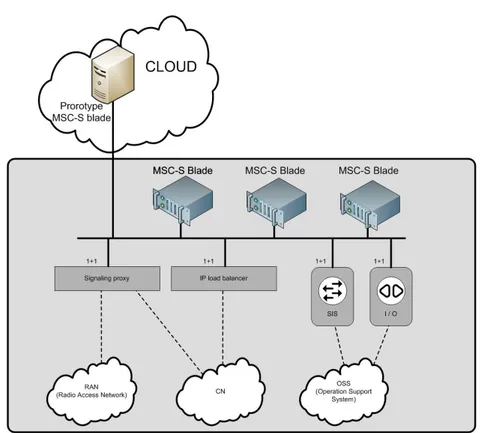
2.3.1. OverviewThis Simplified Infrastructure (SI) prototype was designed as a part of phase-1 and phase-2 [17] as discussed in Section 1.1. In a very generic manner the idea of a SI is presented pictorially using Figure 2.8. The focus here is to indicate that this environment is based upon only IP based connectivity.
2.3. SI PROTOTYPE SUMMARY 35
Figure 2.8. Generic view of the Simplified Infrastructure (SI).
If applied to the MSC-S BC, the same idea will look like as presented with the help of Figure 2.9.
Figure 2.9. Ericsson MSC-S external cluster topology.
The Ericsson MSC-S BC was traditionally implemented in a racked architecture. For the SI prototype used in this study, the design decision was to have an external cluster, meaning that the actual MSC-S BC blade to move out of the rack. For every external MSC-S BC blade which was moved out of the rack, it’s functionalities were emulated on an external server while keeping the rest of the Ericsson MSC-S BC components (MSC-SPX, MSC-SIMSC-S, MXB, EXB etc...) inside rack as it is without any modifications.
All the prototype MSC-S BC blades made to communicate with the rest of the components through a switch (EXB), which was the same method as the other attached system which was communicating to the rest of the system. All the remaining elements necessary for the simulated mobile network to work (HLR, MGW, BSC, RAN, etc...) were also located in the same premise as the racked system of the MSC-S BC. Though simulated mobile traffic was not really used during the current study verification strategy.