DISSERTATION
ALTERATIONS IN LUMBAR SPINE MECHANICS DUE TO DEGENERATIVE DISC DISEASE
Submitted by Ugur Murat Ayturk
Department of Mechanical Engineering
In partial fulfillment of the requirements for the degree of Doctor of Philosophy
Colorado State University Fort Collins, Colorado
Fall 2010
Doctoral Committee:
Department Head: Susan James Advisor: Christian M. Puttlitz Susan James
Xianghong Qian Paul Heyliger
Copyright by Ugur Murat Ayturk 2010 All Rights Reserved
ii ABSTRACT
ALTERATIONS IN LUMBAR SPINE MECHANICS DUE TO DEGENERATIVE DISC DISEASE
Degenerative disc disease is a major source of low back pain. It is hypothesized to significantly alter the biomechanics of the lumbar spine both at the tissue and motion segment (multi-vertebral) levels. However, explicit correlations between the former and the latter has not been established, and this critical link is only possible through modeling the intervertebral disc tissue behavior within a constitutive framework and implementing it in a finite element model of the lumbar spine.
In order to develop a better appreciation of the biomechanics of disc degeneration, the main objectives of this dissertation work were to investigate the degenerative disease related mechanical alterations on lumbar spine through finite element modeling and experimentation, and evaluate the contemporary treatment strategies. To meet this objective, a finite element model of the healthy human lumbar spine was generated based on computed tomography (CT) imagery. Mesh convergence was verified based on strain energy density predictions. Kinematic and mechanical predictions of clinical interest, including range of motion and intradiscal nuclear pressure, were validated under pure moment loading.
The mechanical properties of healthy and degenerated annulus fibrosus tissue were quantified using an orthotropic continuum model, with empirical determination of the requisite material coefficients derived from biaxial and uniaxial tension tests. The resultant material
iii
models were implemented into the validated finite element model in order to simulate disc degeneration at the L3-L4 level. At the tissue level, degeneration was found to significantly increase the dispersion in the collagen fiber orientation and the nonlinearity of the fiber mechanical behavior. At the motion segment level, degeneration increased the mobility of the spine, with concomitant increases in the local stress predictions in the annulus and facet force transmission. Our results were in good agreement with the clinical findings of instability and injury to the intervertebral disc due to degeneration.
Total disc replacement was also considered as a treatment option within the aforementioned finite element framework. The model predictions indicated that single and two-level disc replacement restored motion at the treated two-levels, while linearizing the kinematic response and increasing the facet force transmission. The data reflect that the successful surgical outcome is most likely obtained when maximum preservation of native disc tissue is achieved during implantation of the prosthetic device.
Ugur M. Ayturk Department of Mechanical Engineering Colorado State University Fort Collins, CO Fall 2010
iv
ACKNOWLEDGMENTS
I know by experience that this is the hardest part of a thesis to write. I also know that a couple of months are enough to develop the cynicism to look back and harshly criticize your work. This is probably the very reason for my hesitation in writing these pages: glorifying your own work while it is fresh (and possibly immature). Nevertheless, these will be my own ever-evolving self perception and opinions, and should not stop me from giving the well-deserved credit to certain people who have contributed to this work. Here goes:
Dr. Christian Puttlitz: The wise man, the graduate advisor, the good friend, and the mentor who failed at teaching me how to use the word “the” appropriately. Other than that, I think he has done a pretty good job. All kidding aside, his guidance (six years and counting) has been the foundation of all that I have learned and done in the field of orthopaedic biomechanics. Thank you for everything. Stay thirsty my friend.
My committee members: Dr. Susan James, Dr. Xianghong Qian and Dr. Paul Heyliger not only improved this dissertation with their constructive criticism, but also made a huge impact on my professional development by teaching many graduate-level courses I had the fortune to attend.
Dr. Jose J Garcia from Universidad del Valle, Cali, Colombia kindly shared his expertise in soft tissue mechanics, and has helped me tremendously especially during the model development and experimental design stages. He also acted as a co-author for part of the work presented here, which was published as a peer-reviewed journal article.
v
The suggestions of Dr. Vikas Patel from University of Colorado-Denver were very helpful in CT image analysis and geometry reconstruction. I would like to thank him for evaluating the MR images of several intervertebral disc specimens and thus laying the groundwork for the remainder of the experimental work. Dr. Patel is the co-author of numerous abstracts (as part of the numerical and experimental findings reported in this dissertation) I have presented in scientific meetings over the years.
I would also like to thank Mr. Jim zumBrunnen from CASE, Colorado State University, who has been very helpful with the statistical analysis of experimental data.
Members of the Orthopaedic Bioengineering Research Laboratory: Cecily Broomfield handled the specimen orders, made sure I was paid on a regular basis and could travel to a number of conferences, and kept everything in the lab in order. Ben Gadomski improved many aspects of the computational model I have developed, and made it much better than I imagined it would be. Devin Leahy helped with the machining of several parts during the fixturing of the experimental setup without a single complaint. As a sign of great empathy, he bought me a “Bozo the Clown” to blow off some steam when things get tough. Kirk McGilvray built the biaxial testing machine and not only made the biomechanical tests possible, but also reduced the time I had to spend on them significantly with his helpful suggestions and incredible troubleshooting skills. Brandon Santoni is another gifted researcher whose help and mentorship on designing and executing biomechanical experiments were invaluable. Amy Lyons-Santoni patiently showed me how to read histology slides under the microscope, took care of a ridiculous amount of paperwork, and never got tired of buying me wodka (yes that’s a “w”) shots. Dieter Schuldt eagerly evaluated the geometry of the specimens, which required a lot of dissection and coding. His results constituted an integral part of the findings of this work. In addition to being a great
vi
colleague/officemate, Snehal Shetye also bore my constant presence as a roommate over the last year. I’ll make sure I buy him some IPA the next time we see each other. Kevin Troyer helped with the experimental design at different stages of the project, and it was a pleasure to have this humorous and incredibly modest person around. Wes Womack took on modeling challenges very similar to mine. Without his help, the model development process would be much longer and more painful than it was.
I have the best parents in the world. Their encouragement and love made me survive many tough challenges during the course of my tenure at CSU. My younger sister appeared to be (naively) influenced by my interest in biomechanical engineering for a while, but fortunately this did not last long. I keep saying that she’s the smarter sibling for a reason. I love you all, and I will continue to do my best to be worthy of your support.
vii DEDICATION
This dissertation is dedicated to my beautiful fiancée, Dr. Didem Goz. She has walked down the same path with me over the last five years, and made this work possible with her never ending support. At the same time, she has managed become a very successful, yet down to earth scientist.
viii
TABLE OF CONTENTS
Abstract ………..…. ii
Acknowledgments ……… iv
Dedication ………. vii
Table of Contents ……….………. viii
List of Figures ……….… xii
List of Tables ……… xv
CHAPTER 1: Background 1.1 Functional Anatomy of Human Lumbar Spine……….……… 2
1.1.1 Bony Vertebrae……….…. 3
1.1.2 Intervertebral Discs………. 5
1.1.3 Ligaments……… 7
1.2 Degenerative Disc Disease……….… 9
1.2.1 Pathology of Disc Degeneration………..… 10
1.2.2 Changes in the Morphology of the Disc………. 11
1.3 Treatment ……….……… 14
1.4 Summary ……… 16
1.5 Specific Aims ……… 18
ix
CHAPTER 2: The Micromechanical Role of the Annulus Fibrosus Components under Physiological Loading of the Lumbar Spine
2.1 Introduction ……….. 25
2.2 Methods ……….. 26
2.2.1 Reconstruction of Geometry ……….. 26
2.2.2 Material Properties ……… 27
2.2.3 Validation & Model Predictions ……….………….. 30
2.2.4 Annulus Component Prediction Modeling ………... 32
2.3 Results ………..……… 33
2.3.1 Validation Data ………. 33
2.3.2 Annulus Constituent Predictions ………. 35
2.4 Discussion ………..… 38
2.5 Conclusion ………. 41
References ……… 41
CHAPTER 3: Parametric Convergence Sensitivity and Validation of a Finite Element Model of Human Lumbar Spine 3.1 Introduction ……….. 46
3.2 Methods ……….. 48
3.2.1 Mesh Generation ……… 48
3.2.2 Material Properties ……….….. 49
3.2.3 Loading and Boundary Conditions ……….…. 51
3.2.4 Mesh Convergence ……… 52 3.2.5 Validation ………. 53 3.3 Results ……….. 54 3.3.1 Mesh Convergence ………... 54 3.3.2 Validation ………. 56 3.4 Discussion ………..……… 61 3.4.1 Mesh Convergence ……….……….. 61
x
3.4.2 Validation ……….……… 63
3.5 Conclusion ………. 66
References ………. 66
CHAPTER 4: Development of Orthotropic Continuum Models of Healthy and Degenerated Annulus Fibrosus Based on a Biaxial Testing Protocol 4.1 Introduction ………. 71 4.2 Methods ………. 73 4.2.1 Specimen Preparation ……….……….. 73 4.2.2 Mechanical Testing ……….………. 75 4.2.3 Constitutive Modeling ……… 77 4.3 Results ……….. 79 4.4 Discussion ……….. 81 4.5 Conclusion ………. 84 References ………... 85
CHAPTER 5: Finite Element Modeling of Degeneration-Related Changes in Lumbar Spine Biomechanics 5.1 Introduction ………. 89
5.2 Methods ………. 92
5.2.1 Finite Element Model Development ……….…..… 92
5.2.2 Modeling the Intervertebral Disc ……….…….. 93
5.2.3 Model Predictions & Boundary Conditions ……….……. 95
5.3 Results ……….. 96
5.4 Discussion ……….……….. 100
5.5 Conclusion ……….. 103
References ……….. 103
CHAPTER 6: A Finite Element Study of One- and Two-Level Disc Replacement in the Lumbar Spine
xi
6.1 Introduction ……….…………. 108
6.2 Methods ……… 109
6.2.1 Finite Element Model Development ………... 109
6.2.2 ProDisc-L Modeling …….……….. 110
6.2.3 Implantation & Annular Resection ………..……..…. 111
6.2.4 Bi-level Treatment ……….………. 111 6.2.5 Testing ………. 112 6.3 Results ………... 113 6.3.1 Annular Resection ……….. 113 6.3.2 Bi-level Treatment ……….……. 113 6.4 Discussion ……….……….. 118 6.5 Conclusion ……….. 125 References ……….. 126 CHAPTER 7: Conclusion 7.1 Summary of Findings & Future Work ……….……. 129
xii LIST OF FIGURES
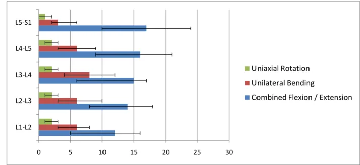
Figure 1.1: Average physiological ROM of lumbar motion segments ……….……….. 3
Figure 1.2: A lumbar vertebra with its extremities ……….……… 5
Figure 1.3: Components of the intervertebral disc ……….………... 5
Figure 1.4: Tensile-compressive behavior of annulus fibrosus ……….………. 7
Figure 1.5: Tensile mechanical behavior of spinal ligaments ……….. 8
Figure 1.6: Sagittal cut view of lumbar spine showing spinal ligaments ………. 9
Figure 1.7: Common intervertebral disc related issues ……… 9
Figure 1.8: Four stages of disc degeneration ………... 13
Figure 1.9: Posterior and lateral views of fusion ……….………..………... 15
Figure 1.10: Charite and ProDisc-L artificial discs ………..………… 16
Figure 2.1: A sagittal cut-view of the functional spinal unit ……….. 27
Figure 2.2: Tensile mechanical behavior of the annulus material in the radial direction ………. 29
Figure 2.3: Intradiscal nuclear pressure predictions of the intact model ………. 31
Figure 2.4: Maximum principal strain predictions at the anterolateral cortical surface ………… 32
Figure 2.5: Moment-rotation response of the functional spinal unit ……….. 34
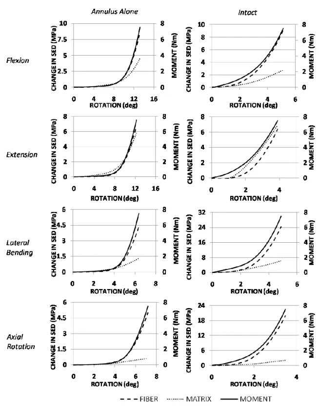
Figure 2.6: Total SED predictions for the annulus ground substance and fibers ………. 36
Figure 2.7: Load-sharing between the fibers and ground substance of the annulus ……… 37
Figure 2.8: Local annular SED distribution ……….. 39
Figure 3.1: The model with three mesh resolutions ………. 52
xiii
Figure 3.3: The intersegmental rotation predictions under flexion and extension loading …….. 56
Figure 3.4: The intersegmental rotation predictions under lateral bending ……….…….. 57
Figure 3.5: Intradiscal nuclear pressure predictions of the model ……….. 58
Figure 3.6: Anterolateral cortical bone strain predictions of the model ……….. 59
Figure 3.7: Facet force transmission predictions ……….. 60
Figure 3.8: Anterior longitudinal ligament strain between levels L2 and L3 ……….. 61
Figure 4.1: Sagittal MR images of representative healthy and degenerated discs ……… 75
Figure 4.2: The specimen dissection orientations for the uniaxial and biaxial experiments …….. 75
Figure 4.3: A biaxial sample ………….……… 76
Figure 4.4: The biaxial testing system utilized in the tension experiments ………... 77
Figure 4.5: Typical stress measurements from uniaxial and biaxial tests ……….….. 81
Figure 4.6: Model predictions and stress measurements for a healthy sample ……….… 82
Figure 4.7: Model predictions and stress measurements for a degenerated sample ……… 84
Figure 5.1: The range of motion predictions under pure-moment loading ……… 97
Figure 5.2: Local intradiscal von Mises stress predictions ……….. 98
Figure 5.3: The percentage contribution of the matrix component ………..……. 99
Figure 5.4: Mean intradiscal nuclear pressure predictions ……… 99
Figure 5.5: Facet force transmission under extension and axial rotation loading ………..… 100
Figure 5.6: Total force predictions for the ligaments ……….. 100
Figure 6.1: ProDisc meshed with 8-noded hexagonal elements ………..……….. 112
Figure 6.2: ProDisc implantation ……… 113
xiv
Figure 6.4: Range of motion for annular resection variants in unilateral bending ………. 116 Figure 6.5: Range of motion for annular resection variants in uniaxial rotation ………. 117 Figure 6.6: Force transmission through the implant and the facet force transmission ………….. 118 Figure 6.7: Range of motion for single- and bi-level arthroplasty in flexion and extension ….... 120 Figure 6.8: Range of motion for single- and bi-level arthroplasty in unilateral bending ….…... 121 Figure 6.9: Range of motion for single- and bi-level arthroplasty in uniaxial rotation ………. 122 Figure 6.10: Facet force transmission and the mean intradiscal pressure predictions ……… 123
xv LIST OF TABLES
Table 2.1: Summary of the mechanical properties ……….. 30
Table 2.2: The magnitude of maximum outward disc bulge ………. 33
Table 3.1: Summary of the mechanical properties ……….………….. 50
Table 3.2: Summary of changes in mesh density ……….…….. 51
Table 3.3: ROM predictions under 7.5 Nm pure-moment loading in three directions …….……. 57
Table 4.1: The optimized coefficients for healthy and degenerated groups ……….…… 81
Table 5.1: Summary of the mechanical properties ……….. 95
1 CHAPTER 1:
2
1.1 FUNCTIONAL ANATOMY OF HUMAN LUMBAR SPINE
The human lumbar spine is a load bearing structure that carries and transfers the weight of the upper body to the lower extremities through the sacrum and the pelvis. Its mechanical function is not only limited to resisting multi-dimensional loads, but it also confers a certain range of mobility to the upper body via tissue deformation.
The lumbar spine consists of 5 bony vertebral elements connected to each other through avascular intervertebral discs (semi-joints) anteriorly and articulating facet joints (full-joints) posteriorly both at the inferior and superior ends. This repeating pattern comes to an end at the inferior aspect of L5 (lumbosacral junction), where this vertebra is also connected to the sacrum through an intervertebral disc and two articulating facet joints.
The combination of the physiologic loads and moments on this multi-joint complex yield different ranges of segmental motion (ROM) at each level (Figure 1.1). However, this load-displacement relationship is commonly nonlinear. Furthermore, relatively small loads generate large displacements due to low tension in the ligaments and the intervertebral disc, resulting in an initially compliant kinetic response known as the neutral zone. The neutral zone (NZ) is regarded as a measure of the joint laxity, and its magnitude can be significantly altered as a result of injuries to the disc such as degeneration or herniation (Mimura, et al., 1994). Excessive changes in the extent of the NZ have been theorized to be predictors of spinal instability, and therefore, it is an important diagnostic parameter in detecting the aforementioned injuries and diseases.
There is an increasing trend of range of motion in the inferior direction from L1 to S1; however no significant differences are reported except between the lumbosacral level and all of the intra-lumbar levels (Guan, et al., 2007).
3
Figure 1.1: Average physiological ROM (in degrees) of lumbar motion segments in principal loading axes. Error bars indicate the normal physiologic limits (Panjabi, et al., 1990).
1.1.1 Bony Vertebrae
The two major components of the vertebrae are the cortical and trabecular bone. While the former is significantly stiffer and denser, the latter has a sponge-like porous structure which produces a globally more compliant behavior. Several studies have shown that aging leads to different levels of reduction in the solid volume fraction in trabecular bone, and, in severe cases, this leads to osteoporosis (Adams, et al., 2002). Moreover, physiological loading is known to affect the bone remodeling process, with the major trabecular orientation coincident with the principal loading directions (Freiberg, 1902).
0 5 10 15 20 25 30 L1-L2 L2-L3 L3-L4 L4-L5 L5-S1 Uniaxial Rotation Unilateral Bending
4
In the anterior column, a stiff cortical shell encloses a trabecular core, and this structural feature becomes especially advantageous under compressive loads. The cortical endplate distributes the load almost uniformly over the trabecular bone, providing additional support at the radial extrema. The posterior elements have an extremely complex geometry, and the “spinal canal” encompasses the volume between these elements and the vertebral bodies (Figure 1.2). This provides a physical, protective environment for the spinal cord. A total of four facets in the inferior and superior regions form the zygapophyseal joints through articulation with superior and inferior adjacent vertebral levels. Bilateral transverse processes and the pedicles at the posterior extremities serve as ligament insertion sites, transmitting force between each level and improving stability.
The reduction in the bone quality in many cases is followed by endplate fractures or critical damage on the vertebral bodies, preventing the vertebra from carrying out its primary load-carrying function (Bogduk, 1999). Bone cement injection and vertebroplasty are current techniques of surgical intervention which seek to provide immediate stability to the spine.
The aforementioned types of bone tissue are known to undergo infinitesimal deformations in vivo during the activities of daily living. Therefore, a simplistic approach such as linear elasticity is sufficient for describing the physiological mechanical response of these tissues (Crawford, et al., 2003). Orthotropic and fully isotropic constitutive relationships have been proposed, and a large range of elastic moduli values are reported in the literature.
5
Figure 1.2: A lumbar vertebra with its extremities (Mosby, 2004)
1.1.2 Intervertebral Discs
The intervertebral discs are bound to the vertebral bodies inferiorly and superiorly through cartilaginous endplates (Figure 1.3). Nutrients are transported to the avascular discs through these hyaline cartilage tissues via
diffusion. Furthermore, these tissues are innervated at the periphery. Aging and/or chemically induced degeneration produces distortion and mineralizes the endplates, which is believed to cause significant pain, as well as increase the risk of endplate fracture
and collapse of the intradiscal space. Decreased permeability of the endplates is shown to change the mechanical loading environment inside the disc (Natarajan, et al., 2006). The elasto-static behavior of this tissue is usually accepted as linear in the non-degenerated discs (Dooris, et al., 2001) (Schmidt, et al., 2007).
The core of the intradiscal space, the “nucleus pulposus”, is a proteoglycan-rich viscous material. Negatively charged glycosaminoglycans (GAG), proteoglycans (PG), Type II collagen and water are the main constituents of this tissue. The random orientation of the collagen fibers
Figure 1.3: Components of the intervertebral disc: Endplates at the superior and inferior boundaries, nucleus at the core surrounded by the annulus at the radial periphery.
6
demonstrates the lack of a structured organization, which consequently generates an isotropic mechanical response (Guerin and Elliott 2006). Furthermore, the negative charges and the presence of PGs result in a high swelling pressure throughout the tissue. This pressure is substantially elevated under the application of compressive loads, and balances itself by creating circumferential “hoop” stresses in the annular lamellae (Adams, et al., 2002).
The annulus fibrosus consists of several lamellae wrapped around the nucleus. These individual layers are composed of PGs and Type I collagen. The collagen molecules form a highly organized fiber network, which reinforces the ground material along local orientations and creates the anisotropic material behavior. The orientation of these fibers ranges from 23 to 45 degrees with respect to the horizontal plane, and these orientations vary from the outer to inner annulus (Guerin, et al., 2006).
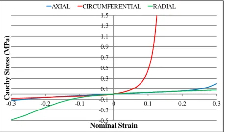
The anisotropic behavior of the annulus can be described with a transverse isotropy model within a cylindrical coordinate system. Three dimensional finite element modeling (FEM) approaches allow for the geometric representation of individual fibers, and consequently reinforcement in the preferred orientation (Dooris, et al., 2001) (Zander, et al., 2001). This approach gives satisfactory results in terms of predicting the global, structural kinetic response; however modeling of the tissue-level mechanics of the annulus requires a more rigorous technique. Spencer’s continuum model for orthotropic materials with multiple fiber families has been employed in previous studies to achieve adequate modeling fidelity (Spencer, 1984). The invariant-based strain energy potentials can be decomposed into individual components of physiological relevance (potentials of the proteoglycan-rich matrix, tissue incompressibility, collagen fibers, etc.) (Wagner, et al., 2004) (Guerin HL, 2007) in order to simulate the nonlinear mechanical behavior of the annulus fibrosus (Figure 1.4).
7
Figure 1.4: Tensile-compressive behavior of annulus fibrosus in three principal loading directions (Wagner, et al., 2004)
1.1.3 Ligaments
Spinal ligaments have a significant effect on the mobility of motion segments, and, therefore, are crucial for understanding and predicting spinal biomechanics (Zander, Rohlmann and Bergmann 2004). Similar to tendons, ligaments primarily consist of Type I collagen, elastin, PGs and water with minor amounts of other proteins and different types of collagen (Panjabi, et al., 1990). With the collagen fibers aligned in the usual loading direction, their mechanical behavior is highly anisotropic. Transverse isotropy is a sufficiently accurate model to describe and model this behavior (Woo, et al., 2005).
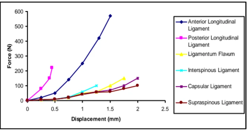
The presence of the collagen fiber results in a highly nonlinear static tensile behavior and increases the global strength of the tissue. The mechanical properties of spinal ligaments have been quantified in numerous studies in the past, and substantial differences are observed between the responses of different ligaments (Zander, Rohlmann and Bergmann 2004) (Figure 1.5). -0.5 -0.3 -0.1 0.1 0.3 0.5 0.7 0.9 1.1 1.3 1.5 -0.3Ca -0.2 -0.1 0 0.1 0.2 0.3 uchy St res s (M P a ) Nominal Strain
8
Figure 1.5: Tensile mechanical behavior of spinal ligaments
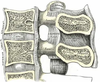
There are six major spinal ligaments that connect the vertebral bodies and the posterior elements in the lumbar region: Anterior longitudinal ligament (ALL) runs through the entire spine from the sacrum to the cervical region, inserting into the anterior surfaces of the vertebral bodies and covering their associated intervertebral discs. Similarly, the posterior longitudinal ligament (PLL) extends in the same range in the inferior – superior direction, inserting into the posterior surfaces of their associated vertebral bodies along the spinal canal (Figure 1.6).
On the posterior side of the spinal canal, the ligamentum flava (LF) connect the laminae of each vertebral body to its subsequent inferior and superior levels. Likewise, the infraspinous ligament (IFL) inserts into spinous processes at the inferior and superior ends and supraspinous ligament (SSL) inserts into the posterior edges at each level. Capsular ligaments provide additional stability around the facets, covering the entire zygapophyseal joint.
0 100 200 300 400 500 600 0 0.5 1 1.5 2 2.5 Displacement (mm) Fo rc e ( N ) Anterior Longitudinal Ligament Posterior Longitudinal Ligament Ligamentum Flavum Interspinous Ligament Capsular Ligament Supraspinous Ligament
9
Figure 1.6: Sagittal cut view of lumbar spine showing spinal ligaments in the two dimensional plane (Mosby, 2004).
1.2 DEGENERATIVE DISC DISEASE
The characteristic effects of the degenerative disease and aging on the intervertebral disc are very similar. Consequently, biochemical
degradation and reduction in the mechanical properties of the intervertebral discs are common problems in the elderly population due to their tendencies to make traumatic injuries more likely to happen during daily physical activities. In vitro experimentation has demonstrated that excessive loading of the disc is likely to fail the vertebral endplate first rather than the disc itself (Adams, et al., 2002). Therefore, herniation and fissures in a healthy disc can only be generated under
the combined application of excessive bending and compressive loads (Adams, et al., 1985). Figure 1.7: Common intervertebral disc related issues (http://www.sandiego- spine.com/subject.php?pn=lumbar-disc-disease-035).
10
However, during the early stages of degeneration, herniation is more likely to occur due to the significant reduction in the strength of the annulus fibrosus.
In such cases, annular tissue is strained radially in the postero-lateral direction, penetrating into the spinal canal and putting pressure on the spinal cord and nerve roots (Figure 1.7). This resultant “nerve pinching” mechanism is a major source of low back pain, and in many cases, can only be treated operatively. The current gold standard in surgical treatment of the aforementioned problem is fusion, wherein the injured disc tissue is completely removed and two adjacent vertebral bodies are fused to each other using instrumentation. It has been postulated that replacing the nucleus with a hydrogel substance can restore the intradiscal pressure, provided that the damage to the annulus is not too severe. However, the use of artificial discs, which are essentially metal-polymer-metal joint constructs, is becoming more common due their ability to preserve the intact state of mobility (as compared to fusion).
1.2.1 Pathology of Disc Degeneration
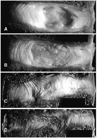
The underlying mechanics of lumbar disc degeneration disease is still not entirely clear. Yet, with aging, the biochemical composition of the disc is known to change. Classification of disc degeneration assessment is clinically achieved in the literature by assigning grades depending on the severity of the disease. The “Thompson Scale” is a commonly used grading scheme by clinicians and researchers, and it groups the progression of the morphological changes in the disc into four stages (Figure 1.8). Grade I represents the healthy disc, with the nucleus being a bright colored viscous fluid at the core of the disc, the cartilaginous endplates are highly permeable, and the fibrous layers of the annulus are distinct and organized. At Grade II, a slight discolorization of the nucleus is visible and it appears more like a solid tissue. In Grade III discs, it is not possible to observe the boundary between the annulus and nucleus, the
11
annular layers are disintegrated and locally ruptured, and the endplates are calcified. Finally, at Grade IV, the annulus and nucleus are completely indistinguishable, the disc height is substantially reduced, and it is not possible to identify the individual layers of the annulus (Thompson, et al., 1990).
The intervertebral disc is the largest avascular tissue in the human body. Therefore, minor disruptions or injuries to the individual components of the tissue might become rather severe in the long-term due to the difficulties in healing. While fissures and tears in the annular lamellae are common during the late stages of degeneration, reductions in mechanical strength of the annulus can lead to excessive bulging and even herniation at earlier time points in the degeneration cascade. A progressive reduction in disc height can be observed, in addition to the formation of osteophytes and loss of integrity of the bony endplate (Goel, et al., 2006). Overall, the degenerative changes in the morphology and mechanics of the disc are significant and often inter-related, and are described in more detail in the following sub-sections.
1.2.2 Changes in the Morphology of the Intervertebral Disc
Degeneration has been postulated to initiate within the nucleus pulposus tissue. Water comprises 90 % of the weight of the healthy nucleus pulposus in children, and its content decreases to 70% in adulthood (Antoniu, et al., 1996). Reduction of hydration initiates inside the nucleus, and subsequently, dehydration begins to affect the remainder of the intervertebral disc. Degenerated nucleus pulposus is shown to include increased levels of matrix-metalloproteinases (MMPs), which stimulate the breakdown of PGs (Stokes, et al., 2005). Furthermore, the total content of Type II collagen is significantly decreased, while there is an increase in the level of Type I collagen content (Andersson, 1998). With these biochemical changes and the increased resemblance of a solid tissue (rather than a fluid-filled structure due
12
to the reduced water content), the nucleus starts to become a more fibrotic structure. Indeed, in the later stages of degeneration, the annulus and nucleus become histologically indistinguishable.
An immediate loss of functionality and progressive calcification of the cartilaginous endplates accompanies these changes in the nucleus. Blood vessels and nerve endings are observed to grow from the vertebral bodies to inside the disc, since there is limited or no osmotic transportation through the endplates (Bernick, et al., 1982). Cracks and fissures are also common along the surface of the bony endplates.
In addition to increased cross-linking among the collagen fibers, the water content in the annulus is decreased. These microstructural changes in the annulus have a definitive mechanical outcome. Due to the loss of water content and the breakdown of the PGs, the hydrostatic pressurization in the nucleus is lost, and consequently the in situ circumferential tension in the annular lamellae disappears (Meakin, et al., 2001). The lack of tension in the annulus tissue increases the catabolic effect of MMPs significantly (Lotz, et al., 2008), leading to a further reduction in the PG content (and thus hydration). Moreover, under in vivo compressive loads, this lack of pre-existing tension causes the individual layers to buckle and delaminate, rather than radially bulge. In fact, in the later stages of degeneration, the disintegration of the annular lamellae with rupture and buckling of the collagen fiber bundles can be observed (Iatridis, et al., 2004). Furthermore, due to this increased axial deformation, the intradiscal space becomes narrower.
13
Figure 1.8: Four stages of disc degeneration from Grade I to IV are demonstrated from A to D respectively (Guerin, et al., 2006).
Osteophyte formation often accompanies disc degeneration around the rim of the endplate. It has been hypothesized that this is actually a remodeling phenomena wherein these changes increase the cross sectional area of the endplate and distribute the loads to a broader area (Adams, et al., 2002). However, these mineralized tissues do not display a consistent pattern and usually encompass random geometry. Recently published data suggest that these mineralized deposits contribute to the global resistance of the functional spinal unit primarily under bending loads (Al-Rawahi, et al., 2010). Furthermore, osteoarthritic involvement in the
14
zygapophyseal joints usually follows disc degeneration due to severe changes in the load-sharing relationship between the anterior and posterior spinal columns (Niosi, et al., 2004).
These degeneration-related changes in the morphology of the intervertebral disc constituents are, in fact, reflected in their biomechanical behavior as well. A rigorous characterization of the material behavior in correlation with the degree of degeneration is necessary in order to accurately assess the effects of the disease on spinal motion segments. The following sections (specifically Chapters 4 and 5) review the existing literature with respect to the alterations of the mechanics of intervertebral disc components due to degeneration. These portions of this dissertation also document the generation of an empirically-based continuum model for degenerated annulus fibrosus.
1.3 TREATMENT
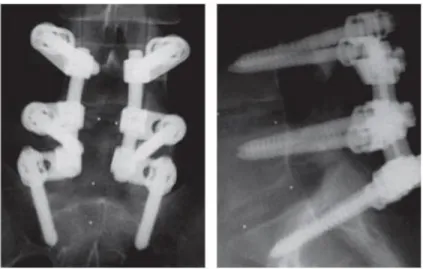
Fusion has remained the gold standard with respect to surgical intervention of disc-related issues in the lumbar spine for the last few decades. Following the removal of the disc tissue, the intradiscal space is filled with bone graft and the injured level and its adjacent segments are reinforced with instrumentation (Figure 1.9) (Kruyt, et al., 2004). This method has been successful in providing pain relief in the short term. However, long-term follow-up studies show that the alteration in the biomechanics and kinematics of the treated segment affect the adjacent levels (Weinhoffer, et al., 1995) (Lee, et al., 1984). An initial increase in the intradiscal pressure and endplate stresses may be contributing to the subsequent degeneration cascade (Eck, et al., 1999).
15
Figure 1.9: Posterior (left) and lateral (right) views of fusion with posterior application of rods and pedicle screws to L4-S1 (Rutherford, et al., 2007).
In an attempt to overcome these shortcomings, the use of dynamic stabilization systems has been proposed as an alternative to the traditional fusion techniques. These posterior spring-rod mechanisms shift the center of rotation posteriorly and are generally intended to unload the anterior column. However, dynamic stabilization is a relatively new concept, and its efficacy still remains unknown since the long term follow-up results are yet to be reported.
Nucleus replacement alone aims at restoring the in vivo intradiscal pressure by replacing the nucleus with a hydrogel implant. It is relatively less invasive and is intended to be applied at the early stages of degeneration where the integrity of the annulus and the endplates are preserved. It is hypothesized that a return of nuclear pressure will arrest or prevent further progression of the degeneration (Marcolongo, et al., 2006).
Disc arthroplasty has become more common over the last decade and is much more promising with its potential to restore the kinematics and biomechanics of the injured segment. Fernstrom was the first to try a motion preserving implant instead of fusion during the 1960s. His primitive device was a simple stainless steel sphere that was implanted following the
16
complete removal of the disc tissue. It remained inside the disc space due to the compressive forces acting on the implant at regions of
contact with the endplates. However, the highly limited contact area at both endplates led to stress concentrations and eventually failure/penetration into the vertebral bodies. A second disc arthroplasty design attempt was introduced with the launch of AcroFlex in the
following decade. This implant was similar to the state-of-the-art designs in that it filled the intradiscal space completely and was a metal-polymer-metal construct. This implant has evolved through several design iterations and clinical trials. Early mechanical failures of the polymer core led to the current state-of-the-art concept of designing the implant as an artificial joint, where the metal endplates articulate with the polymer core material (Kurtz, 2006).
Currently, two devices are approved by the FDA and commercially available for surgical use. The Charite and ProDisc designs (Figure 1.10) are both based on the aforementioned metal-polymer-metal design, and include mobile and fixed polymer core material.
1.4 SUMMARY
The literature on the biomechanics of degenerative disc disease is replete. Alterations in the biomechanical properties of the diseased disc tissue and spinal motion segments have been investigated with respect to a spectrum of outcome (e.g., range of motion, elastic modulus, compressibility, etc.). However, without utilization of these data in a constitutive framework, it is not possible to appreciate the progression of degenerative disc disease and appropriate
Figure 1.10: Charite (A) and ProDiscL (B) artificial discs. The polymer core is fixed to the inferior endplate inside ProDiscL, while it articulates with both of the endplates in Charite.
17
treatment strategies from a biomechanical perspective. Therefore, we hypothesize that a hybrid approach of modeling and experimentation will enable both a rigorous analysis and a parametric assessment of this problem. Specifically, implementation of material coefficients obtained via well designed mechanical experiments on disc tissue in a global finite element model of spinal motion segments will reveal how the structure-function relationship between the intervertebral disc and spine is altered as a result of degeneration.
In order to meet this objective, this dissertation project is focused on: (1) The generation of a valid finite element model of the human lumbar spine; (2) developing an anisotropic hyperelastic material model of the degenerated annulus fibrosus, and (3) implementation of the latter into the former for a thorough evaluation of the biomechanical impact of disc degeneration to the lumbar spine at a global and local level. It is hypothesized that the load-sharing relationship between the individual components of the intervertebral disc (in particular the ground substance and fibers of the annulus fibrosus) will be altered due to degeneration, and these alterations will be reflected in the global kinematic (nonlinear range of motion response) and mechanical behavior (facet force transmission) of the involved motion segments under pure moment loading. Finally, total disc replacement will be evaluated within this developed framework, in order to mechanically assess this clinically available treatment option.
18 1.5 SPECIFIC AIMS
Three specific aims were designated for this dissertation project:
Specific Aim #1: Develop a converged and validated finite element model of the healthy human lumbar spine.
In Chapter 2, the soft tissue component load-sharing relationships of a lumbar functional spinal unit (L4/L5) are investigated using finite element method, and the effects of these relationships on the nonlinear moment-rotation predictions are interrogated. This effort and the employed methodology are extended to generate a finite element model of the lumbar spine (L1/L5) in Chapter 3, with particular detail attention ascribed to the mesh refinement and validation protocols.
Specific Aim #2: Develop a nonlinear, anisotropic, constitutive relationship for the mechanical behavior of degenerated human annulus fibrosus, and implement this into the previously developed finite element model.
Chapter 4 describes biaxial and uniaxial tension experiments on healthy and degenerated annulus fibrosus, and the utilization of these data in generation of orthotropic continuum material models. In Chapter 5, these models are implemented in the finite element model of a lumbar functional spinal unit (that is developed and validated in Chapter 2), and the effects of degeneration on local and global biomechanics of the spinal motion segments are reported.
Specific Aim #3: Simulate the implantation of an artificial disc, and evaluate the changes in biomechanical behavior of the spine compared to the healthy and diseased states.
19
In Chapter 6, implementation of the ProDisc-L into the validated finite element model is documented, and the effects of lumbar disc arthroplasty are assessed within the framework of the healthy and degenerative states of the lumbar intervertebral disc.
REFERENCES
Acaroglu, E., Iatridis, J., Setton, L., Foster, R., Mow, V., & Weidenbaum, M. (1995). Degeneration and aging affect the tensile behavior of human lumbar anulus fibrosus. Spine , 2690-2701. Adams, M., & Hutton, W. (1985). Gradual Disc Prolapse. Spine , 524-531.
Adams, M., Bogduk, N., Burton, K., & Dolan, P. (2002). The Biomechanics of Back Pain. London: Churchill Livingstone.
Alini, M., Eisenstein, S., Ito, K., Little, C., Kettler, A., Masuda, K., et al. (2007). Are animal models useful for studying human disc disorders/degeneration? Eur Spine J , 2-19.
Al-Rawahi, M., Luo, J., Pollintine, P., Dolan, P., & Adams, M. (2010). Mechanical Function of Vertebral Body Osteophytes, as Revealed by Experiments on Cadaveric Spines. Spine , In Press. An, H., & Masuda, K. (2006). Relevance of In Vitro and In Vivo Models for Intervertebral Disc Degeneration. J Bone Joint Surg Am , 88-94.
Andersson, G. (1998). What are the age-related changes in the spine? Baillieres Clin Rheumatol , 161-173.
Antoniu, J., Steffen, T., & Nelson, F. (1996). The Human Intervertebral Disc: Evidence for Changes in the Biosynthesis and Denaturation of the Extracellular Matrix with Growth, Maturation, Ageing, and Degeneration. J Clin Invest , 996-1003.
Bernick, S., & Cailliet, R. (1982). Vertebral Endplate Changes with Aging of Human Vertebrae.
Spine , 97-102.
Bogduk, N. (1999). Clinical Anatomy of the Lumbar Spine and Sacrum. London: Churchill Livingstone.
Crawford, R., Rosenberg, W., & Keaveny, T. (2003). Quantitative computed tomography based finite element models of the human lumbar vertebral body: effect of element size on stiffness, damage, and fracture strength predictions. Journal of Biomechanical Engineering , 434-8.
20
Dooris, A., Goel, V., Grosland, N., Gilbertson, L., & Wilder, D. (2001). Load sharing between anterior and posterior elements in a lumbar motion segment implanted with an artificial disc.
Spine , E122-E129.
Eck, J., Humphreys, S., & Hodges, S. (1999). Adjacent-segment degeneration after lumbar fusion: a review of clinical, biomechanical, and radiologic studies. Am J Orthop (Belle Mead NJ). ,
28(6):336-40.
Fazzalari, N., Costi, J., Hearn, T., Fraser, R., Vernon-Roberts, B., Hutchinson, J., et al. (2001). Mechanical and pathologic consequences of induced concentric anular tears in an ovine model.
Spine , 2575-81.
Freiberg. (1902). Wolff's law and the functional pathogenesis of deformity. The American
Journal of Medical Sciences , 956-972.
Fujita, Y., Duncan, N., & Lotz, J. (1997). Radial Tensile Properties of the Lumbar Annulus Fibrosus are Site and Degeneration Dependent. J Orthop Res , 814-819.
Fujiwara, A., Lim, T., An, H., Tanaka, N., Jeon, C., Andersson, G., et al. (2000). The effect of disc degeneration and facet joint osteoarthritis on the segmental flexibility of the lumbar spine.
Spine , 3036-3044.
Goel, V., Sairyo, K., Vishnubhotla, S., Biyani, A., & Ebraheim, N. (2006). Spine Disorders: Implications for Bioengineers. In E. A. Kurtz SM, SPINE Technology Handbook (pp. 145-182). London, UK: Elsevier.
Guan, Y., Yoganandan, N., Moore, J., Pintar, F., Zhang, J., Maiman, D., et al. (2007). Moment-rotation responses of the human lumbosacral spinal column. Journal of Biomechanics , 1975-80. Guerin, H., & Elliott, D. (2006). Degeneration affects the fiber reorientation of human annulus fibrosus under tensile load. Journal of Biomechanics , 1410-1418.
Guerin, H., & Elliott, D. (2007). Quantifying the contributions of structure to annulus fibrosus mechanical function using a nonlinear, anisotropic, hyperelastic model. Journal of Orthopaedic
Research , 508-516.
Guerin, H., & Elliott, D. (2006). Structure and properties of soft tissues in the spine. In E. A. Kurtz SM, SPINE Technology Handbook (pp. 35-62). London: Elsevier.
Hsieh AH, H. D. (2009). Degenerative anular changes induced by puncture are associated with insufficiency of disc biomechanical function. Spine , 998-1005.
Iatridis JC, M. P. (1999). Compression-induced changes in intervertebral disc properties in a rat tail model. Spine , 996-1002.
21
Iatridis JC., S. L. (1998). Degeneration affects the anisotropic and nonlinear behaviors of human anulus fibrosus in compression. J Biomech , 535-544.
Iatridis. (1999). Shear Mechanical Properties of Human Lumbar Annulus Fibrosus. J Orthop Res , 732-737.
Iatridis, J., & Gwynn, I. (2004). Mechanisms for Mechanical Damage in the Intervertebral Disc Annulus Fibrosus. J Biomech , 1165-1175.
Korecki CL, C. J. (2008). Needle puncture injury affects intervertebral disc mechanics and biology in an organ culture model. Spine , 235-41.
Krismer M, H. C. (2000). Motion in lumbar functional spine units during side bending and axial rotation moments depending on the degree of degeneration. Spine , 2020-2027.
Kruyt, M., van Gaalen, S., Oner, F., Verbout, A., de Bruijn, J., & Dhert, W. (2004). Bone tissue engineering and spinal fusion: the potential of hybrid constructs by combining osteoprogenitor cells and scaffolds. Biomaterials , 1463-1473.
Kurtz, S. (2006). Total Disc Arthroplasty. In E. A. Kurtz S, SPINE Technology Handbook (pp. 303-369).
Lee, C., & Langrana, N. (1984). Lumbosacral spinal fusion: a biomechanical study. Spine , 574– 581.
Lotz. (2004). Animal models of intervertebral disc degeneration: lessons learned. Spine , 657-663.
Lotz, J., Hadi, T., Bratton, C., Reiser, K., & Hsieh, A. (2008). Anulus fibrosus tension inhibits degenerative structural changes in lamellar collagen. Eur Spine J , 1149-1159.
Marcolongo, M., Cannella, M., & Massey, C. (2006). Nucleus Replacement of the Intervertebral Disc. In E. A. Kurtz SM, SPINE Technology Handbook (pp. 281-301).
Meakin, J., Redpath, T., & Hukins, D. (2001). The Effect of Partial Removal of the Nucleus Pulposus from the Intervertebral Disc on the Response of the Human Annulus Fibrosus to Compression. Clinical Biomechanics , 121-128.
Mimura, M., Panjabi, M., Oxland, T., Crisco, J., Yamamoto, I., & Vasavada, A. (1994). Disc degeneration affects the multidirectional flexibility of the lumbar spine. Spine , 1371-80. Mosby. (2004). Gray's Anatomy.
Natarajan, R., Williams, J., & Andersson, G. (2006). Modeling changes in intervertebral disc mechanics with degeneration. Journal of Bone and Joint Surgery Supplement 2 , 36-40.
22
Panjabi, M., & White, A. (1990). Clinical Biomechanics of the Spine. Philadelphia: Lippincott Williams & Wilkins.
Rohlmann A, Z. T. (2006). Analysis of the influence of disc degeneration on the mechanical behaviour of a lumbar motion segment using the finite element method. J Biomech , 2484-2490. Ruberté LM, N. R. (2009). Influence of single-level lumbar degenerative disc disease on the behavior of the adjacent segments--a finite element model study. J Biomech. , 341-8. Rutherford, E., Tarplett, L., Davies, E., Harley, J., & King, L. (2007). Lumbar Spine Fusion and Stabilization: Hardware, Techniques, and Imaging Appearances. Radiographics , 1737-1749. Schmidt H, H. F. (2009). Dependency of disc degeneration on shear and tensile strains between annular fiber layers for complex loads. Med Eng Phys .
Schmidt H., K. A. (2007). The risk of disc prolapses with complex loading in different degrees of disc degeneration - a finite element analysis. Clin Biomech , 988-998.
Schmidt, H., Heuer, F., Drumm, J., Klezl, Z., Claes, L., & Wilke, H. (2007). Application of a
calibration method provides more realistic results for a finite element model of a lumbar spinal segment. Clinical Biomechanics , 377-84.
Spencer, A. (1984). Constitutive theory for strongly anisotropic solids. In Spencer, Continuum
Theory of the Mechanics of Fibre-Reinforced Composites (pp. 1-32). New York: Springer Verlag.
Stokes, I., & Iatridis, J. (2005). Biomechanics of the Spine. In H. R. Mow VC, Basic Orthopaedic
Biomechanics and Mechano-Biology (pp. 529-561). Philadelphia: Lippincott Williams & Wilkins.
Thompson, J., Pearce, R., Schechter, M., Adams, M., Tsang, I., & Bishop, P. (1990). Preliminary evaluation of a scheme for grading the gross morphology of the human intervertebral disc. Spine , 411-415.
Wagner, D., & Lotz, J. (2004). Theoretical model and experimental results for the nonlinear elastic behavior of human annulus fibrosus. Journal of Orthopaedic Research , 901-909.
Weinhoffer, S., Guyer, R., Herbert, M., & Griffith, S. (1995). Intradiscal pressure junction and the lumbosacral junction (so-called measurements above an instrumented fusion). Spine , 526–531. Wilke HJ, K. A. (1997). Are sheep spines a valid biomechanical model for human spines? Spine , 2365-2374.
Williams JR, N. R. (2007). Inclusion of regional poroelastic material properties better predicts biomechanical behavior of lumbar discs subjected to dynamic loading. J Biomech , 1981-7. Woo, S., Lee, T., Abramowitch, S., & Gilbert, T. (2005). Structure and function of ligaments and tendons. In H. R. Mow VC, Basic Orthopaedic Biomechanics and Mechano-biology (pp. 301-342). Philadelphia: Lippincott Williams & Wilkins.
23
Zander T, R. A. (2006). Effect of a posterior dynamic implant adjacent to a rigid spinal fixator.
Clin Biomech (Bristol, Avon) , 767-74.
Zander, T., Rohlmann, A., & Bergmann, G. (2004). Influence of ligament stiffness on the mechanical behavior of a functional spinal unit. Journal of Biomechanics , 1107-1111.
Zander, T., Rohlmann, A., Calisse, J., & Bergmann, G. (2001). Effect of bone graft characteristics on the mechanical behavior of the lumbar spine. Clinical Biomechanics , S73-S80.
24
CHAPTER 2:
The Micromechanical Role of the Annulus Fibrosus Components under Physiological
Loading of the Lumbar Spine
(This chapter was published as a Research Article (with Dr. Jose J Garcia and Dr. Christian M. Puttlitz acting as the co-authors of the manuscript) in the Journal of Biomechanical Engineering (132, 061007 (2010)). The text and figures have been adapted with permission from the journal’s publisher, American Society of Mechanical Engineering (ASME).)
25 2.1 INTRODUCTION
The moment-rotation response of spinal motion segments (vertebra-disc-vertebra constructs) is highly nonlinear (Panjabi, et al., 1990). This behavior is often characterized by an initial “neutral zone”, wherein large deformations occur under very small loads, followed by an “elastic region” wherein the response is approximately linear. The presence of the neutral zone has been attributed to the lack of full tension (“slackness”) in the spinal soft tissues, which is established during loading, as well as the creep-related shifting of the hysteresis curve (Panjabi, 1992) (Wilke, et al., 1998). While the effect of ligament mechanics on spinal motion segment kinematics is relatively clear (Zander, et al., 2006), the relationship between the local mechanical properties of the disc and spinal kinematics has not been explicitly established.
The mechanical properties of isolated annulus fibrosus samples under quasi-static loading conditions have been well characterized via numerous experimental and modeling studies (Klisch, et al., 1999) (Elliott, et al., 2001). Simple hyperelastic material models have been successfully employed to represent the ground substance, and the mechanical behavior of the fibers has been described with exponential models (Eberlein, et al., 2001) (Wagner, et al., 2004). However, without translation of these efforts into larger scale modeling of spinal motion segments, the effects of these findings on the global behavior of the spine cannot be appreciated. This length scale “link” is a prerequisite for the successful modeling of other conditions of interest, in particular, degenerative disc disease. Understanding the individual roles of the various spinal components at the tissue level and how they contribute to global mechanics is requisite in order for the biomechanics of disc degeneration to be accurately interpreted. Further, these tissue level property-global function relationships are important for devising sound treatment strategies.
26
While part of the nonlinearity of the kinematic behavior of the spinal motion segments appears to be a consequence of the heterogeneous structure and mechanical properties of the disc tissues, the specific load-sharing relationship between the collageneous fiber network and the ground substance of the annulus fibrosus is not clear within this global framework. This can be explicitly clarified with a “hybrid” modeling approach wherein a strain energy potential capable of simulating the annulus fibrosus mechanical properties is implemented into a relatively larger scale (single motion segment) finite element model. Earlier continuum approaches in modeling of the annulus have focused on establishment of this methodology (Eberlein, et al., 2001) (Wagner, et al., 2004) (Eberlein, et al., 2004). With the application of a rigorous validation protocol, this approach can reveal the specific roles that the disc constituents play under physiological motions, and how these specific constituent roles change with disease and the application of treatment.
Therefore, the objectives of this study were twofold: (1) Generate a valid, high resolution finite element model of a lumbar functional spinal unit (FSU) capable of reproducing the nonlinear kinematic response over physiologically relevant pure-moment loading range; and (2) quantify and compare the individual contributions of the annular ground substance and collagen fiber network during load bearing on the relative local (tissue level) and global (FSU level) scales.
2.2 METHODS
2.2.1 Reconstruction of Geometry
Using computed tomography (CT) scans of a 49 year old female cadaver, a high resolution finite element model of the L4/L5 FSU was generated. Image segmentation was
27
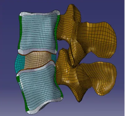
conducted in AMIRA (ver. 4.0, Mercury Computer Systems Inc, Chelmsford, MA), and the resultant three dimensional surfaces were imported into TRUEGRID (XYZ Scientific Applications Inc, Livermore, CA) and meshed. Mesh refinement was achieved through convergence of strain energy density (SED) predictions for individual tissues (Ayturk, et al., 2009). The final mesh consisted of 8-noded hexagonal elements with approximately 230,000 degrees of freedom (Figure 2.1). This model was subsequently imported into ABAQUS CAE (ver. 6.8, SIMULIA, Providence, RI) for further model development.
Figure 2.1: A sagittal cut-view of the functional spinal unit. Cortical (green) and trabecular (light blue) bone, posterior elements (brown), bony (grey) and cartilaginous (red) endplates, annulus (light green) and nucleus (light brown) are demonstrated.
2.2.2 Material Properties
Linearly elastic and transversely isotropic material models were imported from the literature to simulate the mechanical behavior of the osseous tissues (Ueno, et al., 1987) (Whyne, et al., 2001). The material constants of the trabeculae were based on CT image data
28
using previously reported linear regression formulae based on Hounsfield attenuation units (Crawford, et al., 2003). Ligaments were modeled as tension-only, nonlinear springs with previously reported force-displacement relationships (Rohlmann, et al., 2006). The nucleus pulposus was modeled as nearly incompressible (Poisson’s ratio: ν = 0.49) and linearly elastic (Dooris, et al., 2001).
The mechanical behavior of the annulus fibrosus was modeled with an orthotropic continuum approach where the mechanical contributions of the fibers and the ground substance were defined over the same physical volume. Utilizing Spencer’s invariant-based method for modeling fiber reinforced composites (Spencer, 1984), a strain energy function was developed for the annulus (Wannulus) as a cumulative function of two separate components
(Wmatrix and Wfiber):
(2.1)
The matrix term was chosen as a third-order reduced polynomial (i.e. Yeoh material) in order to simulate the nonlinearity of the stress-strain response of the ground substance. The governing equation for the incompressible material was taken as:
(2.2)
where C10, C20 and C30 are material coefficients and is the first invariant of deviatoric
component of the Cauchy-Green strain tensor. The coefficients were obtained using optimization schema in ABAQUS CAE in order to give the best fit to the stress-strain response of healthy annulus tissue in the radial direction (Fujita, et al., 1997) (Figure 2.2). Differentiation of Eq. (2.2) with respect to stretch yielded the stress-strain relationship based on stretch and the invariants, in which the error was then minimized with a linear least-squares approximation
29
ABAQUS tool (ABAQUS, 2008). The fibers were represented as an exponential function of the strain invariants, similar to previous examples in the literature (Eberlein, et al., 2001) (Wagner, et al., 2004) (Guerin, et al., 2007):
(2.3)
where I4 and I6 represent the fourth and sixth invariants of the Cauchy-Green strain tensor (C),
respectively:
(2.4)
where a0 and b0 represent the direction cosines of the two fiber families in the undeformed
configuration, and F represents the deformation gradient (Holzapfel, 2000). The material coefficients a3 and b3 were calibrated to fit the
mechanical response of the annulus tissue in the circumferential and axial directions (Wagner, et al., 2004) under tension and compression. The final strain energy function was coded into a user subroutine (UANISOHYPER). Minimum allowable values of the invariants I4 and I6 were
constrained such that the fibers were activated only under tensile loads. The fiber angles were specified to vary between 26° to 45° from the outer layer to the inner layer of the annulus (Schmidt, et al., 2007), respectively, and they were implemented using the local *ORIENTATION command. The material properties chosen for all tissues are summarized in Table 2.1.
Figure 2.2: Tensile mechanical behavior of the annulus material in the radial direction. Experimental data were adapted from graphical data published in (Fujita, et al., 1997).
30
Material Elastic Modulus (MPa) Poisson Ratio Reference Cortical Bone E11 =8000 ν12 = 0.4 (Ueno, et al., 1987)
E22 = 8000 ν13 = 0.35
E33 = 12000 ν23 = 0.3
Trabecular Bone Based on CT images (Crawford, Rosenberg and Keaveny 2003) Posterior Elements E = 3500 ν = 0.3 (Dooris, Goel, et al., 2001) Bony Endplates E = 1000 ν = 0.3 (Whyne, et al., 2001) Facet Cartilage Neo-Hookean, C10 = 2 (Noailly, et al., 2005)
Annulus Fibrosus Fiber reinforced Yeoh Material C10 = 0.0146, C20 = -0.0189 C30 = 0.041
a3 =0.03, b3 = 120.0 (b3 is unitless)
Nucleus Pulposus E = 1 ν = 0.49 (Dooris, et al., 2001) Cartilaginous Endplate E = 23.8 ν = 0.4 (Lu, et al., 1996) Ligaments Exponential force-displacement curves (Rohlmann, et al., 2006)
Table 2.1: Summary of the mechanical properties used in the model
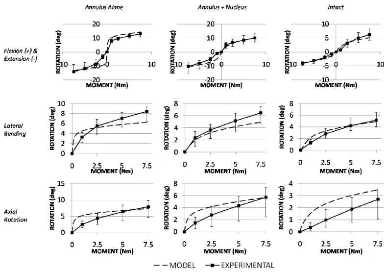
2.2.3 Validation & Model Predictions
Validation of the model was performed following the stepwise protocol previously suggested by Heuer et al. (Heuer, et al., 2007). The FSU was reduced by removal of all ligaments, followed by a complete nucleotomy. Then, during the re-addition of each component, the range of motion (ROM) predictions were compared to available experimental data. The resting pressure inside the nucleus (as described below) and the nonlinear properties of the ligaments were calibrated to provide the best fit when necessary. During the application of this calibration scheme, the FSU was tested under pure moments up to 7.5 Nm in the three principal directions (flexion-extension, lateral bending and axial rotation), without the application of a compressive pre-load as the aforementioned scenario has been shown to yield comparable results with the in
vivo kinematic behavior (Wilke, et al., 2001).
Given that the model was used to predict the loading-motion response and relevant internal mechanical parameters, complete validation of the finite element model of the spine cannot be based on kinematic data alone. Hence, the intradiscal nuclear pressure (both in the
31
prescribed pure-moment-loading scenario and under the application of purely compressive loads) (Figure 2.3), vertebral bone strain (Figure 2.4), and disc bulge (Table 2.2) predictions (defined as the maximum nodal displacement in the area of interest) of the model were also compared with previously published experimental data. While a rather thorough approach is essential to ensure the accuracy of other mechanical predictions, the validation methodology described herein has been constrained to the parameters that are relevant to the scope of this work. A complete description of the entire battery of validation metrics is contained elsewhere (Ayturk, 2007).
Figure 2.3: (Top) Intradiscal nuclear pressure predictions of the intact model under flexion (+ moment) and extension (- moment) loading. The mean and standard deviation values reported for the model represent the nodal variation of the model’s predictions within the nucleus pulposus. The experimental data represent the median, maximum and minimum of a pool of tested specimens, as indicated by the legend (Heuer, et al., 2007). (Bottom) Change in the horizontal and vertical compressive stress components in the antero-posterior direction while the FSU is under compression with the application of 2000N. Dashed lines represent the physical boundaries between the annulus and the nucleus.
32
2.2.4 Annulus Component Prediction Modeling
In addition to ROM, SED predictions were reported for the fiber and ground substance components as a measure of their individual mechanical responses and contributions. Specifically, SED was interpreted as an indicator of the load-sharing relationship between the fibers and the ground substance since it inherently removes any confounding disparities due to volumetric differences between these components that is associated with the aforementioned continuum approach in modeling the annulus fibrosus.
Since the disc maintains a homeostatic, non-zero stress/strain condition in its resting, reference configuration (Wilke, et al., 1999), the nucleus was pressurize d by inducing positive (expansive) isotropic volumetric strain
(using the *THERMAL STRAIN option) on the corresponding nodes at the beginning of each analysis. Consequently, the model predictions were non-zero when no load was applied, and therefore, the “change” in each parameter of interest with respect to this no load reference state was reported. At the end of pressurization, the nodal predictions
(of the deviatoric component of the stress tensor) in the nucleus pulposus were 0.1 + 0.04 MPa (mean + standard deviation), consistent with previously reported in vivo nuclear pressure measurements taken in the transverse position (Thompson, et al., 2003). All solutions were Figure 2.4: Maximum principal strain predictions at the anterolateral cortical surface of L4 under the application of 3Nm of pure moment. Model predictions indicate the mean and standard deviation of nodal predictions in the anterolateral cortical region, while the experimental data indicate the mean and standard deviation in the measurements from a sample pool (n=6) (Ayturk, 2007).