SchoolofInnovation,DesignandEngineering
Development of a tipper
body subframe
-a pre-study at SSAB
Master thesis work
Advanced level,30 credits
Product and process development
Mattias Hägglund
Report no: 2
Commissioned by:SSAB
Supervisor, SSAB: Hans Konradsson
Supervisor, Mälardalen University:Bengt Erik Gustafsson Examiner:StenGrahn
© Mattias Hägglund 2 Page intentionally left blank
© Mattias Hägglund 3
ABSTRACT
This thesis is performed on master level and covers an assignment given by the Value Added Services(VAS) department at SSAB (Oxelösund, Sweden). The thesis has been carried out by Mattias Hägglundduring the fall of 2014 atMälardalen University.
The transportation industry has over time developed to be more efficient and environmentally aware. Looking at the truck industry shows that the development is strong and constant, new solutions and improvements is being introduced every year. One result of this is reduced fuel consumption and/or increased loading capacity. In the mining industry for example, can a few hundred kilos extra payload make a big different at the end of the day.
This constant development seen in many fields is something that SSAB wants to take part in. By using product diversification canthe VAS department reach new customers and secure sales of SSAB steel. Subframes, being a natural step from tipper bodies, are worth to consider as a possible project start-up. Combined with SSABs current tipper body program could a new subframe make its way to the market.
This project have adapted a new product development process in order to come up with a subframe design not yet physically tested, but theoretically superior to conventional subframes. Each development phase of this process is explained and executed in the report, giving the reader a detailed step-by-step overview.
The projects result builds on the knowledge attained from the course of the project and simulation results. With the use of a CAD-program and by applying FEM, have a number of concepts been analysed with regards to their strength and rigidity. The simulation results have made it possible to design a final solution where a number of demands and desired properties have been fulfilled.
The result from this thesis work have reduced the weight by 7%, increased rigidity about 20% and substantially improved the strength in comparison to a typical subframe. This shows that there are possibilities to improve on the current subframe design, and that there is cause for SSAB to make further research and development in the subject of tipper body subframes.
© Mattias Hägglund 4
ACKNOWLEDGEMENTS
The author would like to express his gratitude to SSAB in Oxelösund, for the opportunity to write this thesis with them. It has built confident and self-esteem to be trusted with this task. This assignment has been exciting and interesting from the start. Knowing very little while going in to the project and systematically building up information and knowledge have been an exciting journey. I would like to thank a number of people who have supported and helped me throughout this project.
BengtGustavssonat MDH has been key to the success with which the project has concluded. His guidance and support through the simulations have secured the resultshigh quality.
Hans Konradsson,Product Manager at SSAB hasshown strong belief in me and my judgement, being friendly and supportive on,as well as off work.
A special thanks to Jonas Gozzi,Manager Market Development and R&D for taking time and lending his expertise to some of the more critical parts of the project.
The author also wants to thank the persons and companies who took amoment to answer my questions and show me their production facilities. It gave valuable information later used in the development phase.
Finally, thanks to everybody at SSAB who have supported my work and happily answered my questions. You have all made me feel welcome and as part of the group from day one. It has been greatly appreciated.
© Mattias Hägglund 5
CONTENT
1 INTRODUCTION ... 10 1.1 SSAB ... 10 1.2 PROJECT BACKGROUND... 10 1.3 PROBLEM FORMULATION ... 11 1.4 PROJECT AIM ... 11 1.5 RESEARCH QUESTIONS ... 11 1.6 PROJECT LIMITATIONS... 12 1.6.1 Time Frame ... 121.6.2 Vehicles and Equipment ... 12
1.6.3 Result ... 12
2 RESEARCH METHOD ... 13
2.1 RESEARCH APPROACH ... 13
2.1.1 Qualitativeand Quantitative Data. ... 14
2.1.2 Primary and Secondary Data Gathering ... 14
2.1.3 Structured, Semi- and Unstructured Interviews ... 15
2.1.4 Literature Review ... 15
2.2 RESEARCH AND SOURCE CRITICISM ... 16
2.2.1 Interviews ... 16
2.2.2 Literature ... 17
3 THEORETIC FRAMEWORK ... 18
3.1 REFINED NEW PRODUCT DEVELOPMENT PROCESS ... 18
3.2 DEMAND SPECIFICATION ... 19
3.3 GANTT SCHEDULE ... 19
3.4 HIGH STRENGTH STEEL ... 20
3.4.1 Steel Improvements ... 20
3.5 SCANIA RULES AND DIRECTIVES ... 21
3.6 CREATIVE TOOLS ... 22
3.7 SIMULATED DRIVEN CONSTRUCTION ... 22
3.7.1 Finite ElementMethod ... 22 4 EMPIRIC STUDY ... 24 4.1 DEFINE PROBLEM ... 24 4.1.1 Demand Specification ... 25 4.2 PROJECT PLANNING ... 25 4.3 RESEARCH ... 25
4.3.1 Literature and Document Review ... 25
4.3.2 Material Properties ... 26
4.3.3 Reference Subframe(RF) ... 27
4.3.4 Field Study ... 28
4.3.5 Body Building Companies ... 28
4.3.6 Attachments ... 29
4.3.7 Stabiliser ... 30
4.3.8 General Directives for Subframe ... 31
4.3.9 Centre of Gravity ... 32
4.3.10 Tipping Stability ... 33
4.3.11 Effects of Reduced Weight ... 33
4.3.12 Patent Research ... 34
4.4 CONCEPTUAL DESIGN ... 35
4.4.1 Concept Generating Method ... 35
4.4.2 Concept Groups and Descriptions ... 36
4.4.3 Concept Evaluation ... 37
4.5 PRODUCT DEVELOPMENT ... 39
4.5.1 Construction and Simulation Boundaries ... 39
4.5.2 Concept Solution A1: Improved Subframe ... 40
4.5.3 Concept Solution B1:Shaped Plate ... 41
© Mattias Hägglund 6 4.5.5 Material ... 44 4.6 SIMULATION PREPARATION ... 44 4.6.1 Delimitations ... 44 4.6.2 Payload ... 44 4.6.3 AngleDuringUnloading ... 45 4.6.4 Test Parameters ... 45 4.7 SIMULATION RESULTS ... 45 4.7.1 Reference Frame ... 45 4.7.2 ConceptA1: SubframeImprovements ... 46 4.7.3 Concept B1: ShapedPlate ... 47
4.7.4 Concept B2: Octagon Plate ... 47
4.7.5 SummaryofResults ... 48
5 PROJECT RESULT ... 49
5.1 SIZE AND POSITION ... 50
5.2 PARTS AND ASSEMBLY ... 50
5.3 MATERIAL ... 51
6 ANALYSIS AND EVALUATION ... 52
6.1 EVALUATION OF PROJECT PHASES ... 52
6.1.1 Define Problem ... 52
6.1.2 Planning ... 52
6.1.3 Research ... 52
6.1.4 Conceptual Design ... 53
6.1.5 Product Development ... 53
6.2 FINAL RESULT EVALUATION ... 54
6.2.1 Demands Specification ... 56
6.3 ANALYSIS OF RESEARCH QUESTIONS ... 57
7 RECOMMENDATIONS AND CONCLUSION ... 59
7.1 PRODUCT RECOMMENDATIONS ... 59
7.2 PROJECT CONCLUSION ... 59
8 REFERENCES ... 61
© Mattias Hägglund 7
LIST OF FIGURES
Figure 1. Project part 1-3 ... 13
Figure 2. Project NPD-process ... 18
Figure 3. Steel formability and strength. (Globalspec webpage) ... 20
Figure 4. Cost positions. (Trailer Design Guide) ... 21
Figure 5. Triangular (2D) mesh ... 23
Figure 6. Reinforced subframes (SSAB Database) ... 24
Figure 7. Domex range. (Domex range of hot-rolled high strength sheet steel) ... 27
Figure 8. Complete reference subframe ... 27
Figure 9. Reference subframe used for comparison ... 27
Figure 10. Bergs Fegen, located in Fegen, Sweden (Bergs Fegen webpage) ... 28
Figure 11. Wagnfabriken, located in Tranås, Sweden (Wagnfabriken webpage) ... 28
Figure 12. Zetterbergs, located in Östervåla, Sweden (Zetterbergs webpage) ... 28
Figure 13. Rigid weld attachments (Scania doc, Attachments and SSAB Database) ... 29
Figure 14. Flexible attachments (Scania doc, Attachments and SSAB Database) ... 30
Figure 15. Classical Stabiliser (SSAB Database) ... 30
Figure 16. Stabiliser incorporating a hydraulic cylinder (SSAB Database) ... 31
Figure 17. CoG for loaded tipper body ... 32
Figure 18. Unloading at angle (National AG Saftey Database) ... 33
Figure 19. SSAB Extreme performance calculator ... 34
Figure 20. Profile concepts and attachment ... 36
Figure 21. 45 degree subframe concept ... 36
Figure 22. Shaped plate concepts ... 37
Figure 23. Support concepts ... 37
Figure 24. SSAB tipper body (SSAB Database) ... 38
Figure 25. Chassis frame and inflection point ... 38
Figure 26. Strength improvement for closed profiles and cross-tie (Trailer Design Guide) ... 39
Figure 27. Concept solution A1 improved subframe ... 40
Figure 28. Top view of concept A1 ... 41
Figure 29. Concept A1 parts ... 41
Figure 30. Concept solution B1 shaped plate ... 42
Figure 31. Concept B1 reinforcements ... 42
Figure 32. Concept B1 parts ... 42
Figure 33. Concept solution B2 octagon plate ... 43
Figure 34. Octagon plate shape ... 43
Figure 35. Concept B2 parts ... 43
Figure 36. RF stress test ... 46
Figure 37. Concept A1 stress test ... 46
Figure 38. Concept B1 stress test ... 47
Figure 39. Concept B2 stress test ... 48
Figure 40. Final solution SSAB Octagon subframe ... 49
Figure 41. SSAB Octagon subframe measurements ... 50
Figure 42. Octagon plate measurement ... 50
Figure 43. SSAB Octagon subframe parts ... 51
Figure 44. Subframe example (Wagnfabriken) ... 51
Figure 45. Project NPD-process ... 52
Figure 46. SSAB Octagon subframe stress test ... 54
Figure 47. Stress levels at 5 degree ... 55
Figure 48. Stress levels at 10 degree ... 55
© Mattias Hägglund 8
LIST OF TABLES
Table 1.Simulation values and percentage...48 Table 2.SSAB Octagon subframe compared to the RF...49
© Mattias Hägglund 9
ABBREVIATIONS
AHSS Advanced High Strength Steel
Alloy Blend/mix of metals
CAD Computer Aided Design
Dual Phase Steel High strength steel that has a soft (ferrite) and a hard (martensite) microstructure, resulting in a desired combination of good ductility with high strength
Fatigue Deterioration of a materials strength caused by frequent change in the mechanical state of stress.
FEM Finite Element Methods
HSS High Strength Steel
IDT School of Innovation, Design and Engineering
LYNC Windows based communication program
MDH MälardalensHögskola (Mälardalen University)
MC Thermomechanically rolled (M) Cold formed steel (C) NPD-process New Product Development Process
RF Reference Frame
Steel Alloy of iron and carbon with a carbon content below 2.1% Tensile Strength Maximum force that can be applied without the material breaking
VAS Value Added Services
UHSS Ultra High Strength Steel
Yield Strength The maximum force that the steel can withstand without sustaining permanent deformation
© Mattias Hägglund 10
1 INTRODUCTION
Development of a tipper body subframe is a project commissioned by SSAB in Oxelösund. This introduction covers the background and aim of the project.
1.1
SSAB
The history of SSAB is long and interesting. Starting up as three separatesteel-companies between 1878 and 1941, SSAB was created when they decided to combine into one company in 1978. From there, a number of acquisitions made SSAB grow all over the world, the latest, being that of the Finish steel manufacturer Ruukki.
Today, SSAB is a strong actor on the steel market with its foundation in northern Europe. Product names as Weldox, Domex and Hardox are well known brands in the steel related industry and synonymous with high quality.
1.2
Project Background
Over the course of several years it is possible to see a strong development on trucks and flatbeds. During the 21 century truck companies have made great improvements on the truck body with the introduction and smarter use of high strength steel.
Flatbeds have seen a similar development. New constructions and stronger materials have increased the strength and reduced the weight, saving money and emissions along the products lifespan.
However, in comparison to the two above mentioned products, the subframe has seen very low levels of development during its lifetime. There is a range of different manufacturers producing flatbeds with connecting subframe.These producers have their own subframe design, but theyall share very similar traits and appearance, and have done so for a long time.
A few people around the SSAB company have commented on this rather strange fact. With all the focus on improving the truck and flatbed, the subframe seem to have beenleft out. The thoughts on subframes expressed as; why change something that working fine?
This gives room for possible development and improvement. As SSAB is moving into the finishing stages of developing their own tipper body program, they see it as a natural step to studysubframes. With the in-house expertise on the use and construction of steel products, an optimised design making use of thematerials benefits, would give SSAB a product that could transform the way subframesare designed today.Additionally,SSABs high strength steel could give a weight reduction,leading to positive benefits like reduced fuel consumptionand additional loading capacity.
© Mattias Hägglund 11
1.3
Problem Formulation
Central part of designing a quality product is to have a good understanding of the problem. Everyone involved from developer to sales have a different view of what the customer wants. To find out what the customer really needs is crucial and should be allowed to take a lot of time (Ullman, 2010).
When constructing a truck with a tipper body, there is of course a lot to take into consideration. Weight should be minimized without a loss of function, strength and safety. The tipper body needs to be securely attached to the chassis but at the same time allow for some movement to maintain driver comfort. Another important aspect is the centre of gravity in the finished and loaded truck, which should be as low as possible.
All of these attributes are affected by the subframe and its design. Small changes or a complete redesign have to be carefully measured and tested. Breaking new ground in a field that has evolved through many years of trial and error is not, without difficulties.
SSAB has chosen to view this task as a product development pre-study project. In this conservative field, the problem (or opportunity) is described as a lack of innovation and development, opening up for a potentially, new product.
1.4
Project Aim
The aim of this project is to find out if there is enough room to commit to a new product project.SSAB is looking for a 10 percent improvement in strength, rigidity and weight, as well as a reduction in height. The hope is to get a good starting position to launch a project start-up around the possibility to produce an SSAB subframe.
Is it possible to use SSABs steel products and make an improved construction where the introduction of HSS is a central part? Can the design be improved with regards to weight, strength and stability? The aim is to be able to answer these kinds of questions, through research and development. This work is made in an effort to make “a stronger, lighter and more sustainable world” (SSABs vision).
1.5
Research Questions
Research questions should help guide a project without being too specific and restricting. At the conclusion of this project, the report should have answered the following research questions:
RQ1: What are the rules and directives surrounding the construction of a subframe for tipper body trucks?
RQ2: How can high strength steel improve a subframe construction?
RQ3: How can SSAB develop a tipper body subframe with a 10 percent improvement regarding strength, rigidity and weight?
© Mattias Hägglund 12
1.6
Project Limitations
In accordance with SSAB and MälardalenHögskola (MDH)have the following delimitations been chosen for this project.
1.6.1 Time Frame
This project is a master thesis for 30 credit points. Start date is the first of September 2014, end date is the 15 of January 2015 where an oral presentation is held at MDH.
1.6.2 Vehicles and Equipment
The developed subframe should fit on Scania chassis and meet their demands with regards to strength, durability, flexibility and more. Other truck brands will not be included in this first research and developing project.
Tipper body trucks will be the only truck configuration that this project will cover. Tankers, cranes or logging units for example will not be taken in consideration for design or construction of this subframe.
1.6.3 Result
The final result should consist ofa detailed product description. The specific data should be presented and analysed in comparison to anexistingsubframe.
The projects must be described in a paper reportcovering all the phases of the new product development process.
© Mattias Hägglund 13
2 RESEARCH METHOD
This chapter describes the method used during the course of this project.
2.1
Research Approach
This case study has been initiated on the behalf of SSAB´s department Value Added Services(VAS) located in Oxelösund. Material directly given from SSAB own research department Knowledge Service Center (KSC) have served as the information foundation of this study. At KSC, a vast bank of secondary data has been available tapping into material properties and previous research projects. In addition to SSABs own data and research material other sources has been used to widen the input of information. MDH´s library service (web and house based), Google Scholar and public libraries have been sources of secondary data.
Primary data have mostly been gathered from in house meetings, Scanias bodybuilding department and interviews.
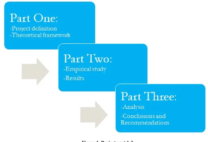
This project is divided into three parts. Each part covers different steps of the project, as seen in figure 1. Note that they are overlapping each other.
Figure 1. Project part 1-3
The product development process used in this project is an adapted version of Ullmans design process from the book The Mechanical Design Process(Ullman, 2010),combinedwith Ulrich andEppingers development process from the bookProduct Design and Development (Ulrich and Eppinger, 2008). This new product development process is explained in detail in chapter 3.1.
© Mattias Hägglund 14 2.1.1 Qualitativeand Quantitative Data.
Quantity, also known as category questions, can seem like easy and straight forward questions. They require a simple short answer, often an exact number or approximation.Quantitative questions are often seen to have pre-selected alternatives answers. The wording of the questions is critical for the outcome and needs careful consideration (Bell, 2006).
Hoxand Boeije(2005) describes quantitative data as data that can be described numerically in terms of objectives, variables, and their values,clearly connecting it to a degree of data volume. The large diversification of subframes made it clear from the start that quantitative questions will be hard to formulate. The result would be ill-founded in reality, where every company might give different answers. Not enough quantitative numbers would be acquired for future analysis. The use of quantitative data is therefore conservative in this report.
Some believed that quantitative data gives little but exact information. This is not true, as large amount of data is generated in a qualitative study. The aim here is to provide an understanding of the complexity of the research problem. This may include transcribed records of interviews, audiovisual material, a diary or chronological account, the researcher's reflective notes made during meetings, jotted notes and more detailed field notes of observational research (Hox and Boeije, 2005).
This project mainly builds on qualitative data gathered from several companies working direct or indirect with subframes and HSS. The methods used to collect qualitative data include ethnographic practices such as directly observing and interviewing working personnel.A large part of this project is to interpret the data and draw correct conclusions. The result will depend heavily on the thoroughness of the analysis of the qualitative data.
2.1.2 Primary and Secondary Data Gathering
When conducting research and development projects, there are two types of data. Primary and Secondary data are both of great importance to a project that wants to build onold, as well as new, information. Primary data is data specifically collected to answer the research problem at hand, using tools that best suits the research problem. Later, when this data is made available for others it becomes secondary data for them. Secondary data is described as data originally collected for a different purposeand reused for other research. (Hox and Boeije, 2005)
This project relies heavily on primary data for its result. The project uses secondary data to plan and structure the method and development process. There is for these tasks an abundance of secondary data available,surrounding the process and tools.
On the main subject of the project however, secondary data have been hard to come by. A few in house projects are touching on the subject but none are taking the problem head on. This leaves primary data as a crucial and necessary part of this project. KSC on SSAB has provided secondary data in the form of reports from similar projects, material properties and more. The library along with internet search engines has also served as tools for secondary data collection. Primary data comes from company visits, interviews conducted with in-house personnel and external customers.
© Mattias Hägglund 15 2.1.3 Structured, Semi- and Unstructured Interviews
The goal of any interview is to ask questions and get answers. This can seem easy enough but the method used in the interview has a big impact on the received answers. No matter how careful we phrase the question, the spoken or written word will always have a residue of ambiguity. Despite that, interviewing is one of the most powerful and common ways we use to understand one another (Fontana andFrey, 1994).
In a structured interview the respondent is asked a set of pre-established questions with a limited set of responses. There is generally little or no room for open end questions, this is to make sure the interview is running along smoothly. The method of recording the information follows a similar pre-decided coding scheme. Thus, all respondents are given the same set of questions, asked in a likewise manner, by an interviewer who repeat the same structure. In other words, there is very little flexibility in the way questions are asked or answers are given in the structured interview setting. (Fontana and Frey, 1994).Surveys are an example of structured interviews which only provides a few pre-decided answers to choose from.
In comparison the unstructured interview method gives a greater span in its qualitative nature. Many qualitative researchers state a difference between unstructured interviews, also known as in depth interviews, and practical observations. Some do however mean that they go hand in hand saying that the information gathered from observations often come from informal interviewing in the field. What Fontana and Frey (1994) means, is that an unstructured interview can, and to some degree should evolve in the heat of the moment. Questions going both ways and followed up with yet more questions to give an in depth understanding of any given issue.
This project has used a mix of the two above mentioned structures. Together they form a Semi-structured interview method. It starts with pre-established questions to decide the topic and get the conversation started. Each question written in a more open manner and is therefore evolving the interview into a more unstructured form. This together with observations and follow up questions sets the interview method adapted in this project.
2.1.4 Literature Review
Every project, no matter the size, will require a large amount of reading. The work performed and the arguments made needs to be supported by other people’s previous writings. This may help with approach and method as well as building a better understanding of the topic. All of this is very important as it will help prepare for the production of the final report (Bell 2006). It falls naturally that the bulk of any literature reading should come early in a project. Performing several tasks at the same time is not uncommon, reading literature being one of them. The worker should however guard against letting reading take up too much of his or her time. The amount of information available is huge and the ability to take out relevant parts from the mass will save much needed time. In the face of this Bell (2006) likes to remind us that we are only human and sometimes have to accept that we cannot do everything. People can only do the best they can and should not use more reading as an excuse to avoid getting down to the main task.
© Mattias Hägglund 16 This project will mainly be based on information gathered from within the SSAB group and other companies with connection to the subframe and its use. The subject for this thesis work is one with low amount of conducted research. This makes the available literature directly connected to the topic very limited. The main part of the literature read in this project comes in the form of theoretical examples.No larger investigation have been done as far as this conducted research have been able to find.
2.2
Research and Source Criticism
Every project builds on gathered information. For the project to be trustworthy, needs the information that it builds upon also be trustworthy. Therefore cannot every piece of information found be taken as facts. It is easy to accept information that supports your claim and goal with little or no consideration, but without source criticism losses your work credibility itself.
Björklundand Paulsson (2012) states in their book Seminarieboken, Attskriva, presenteraochopponera, that there are three ways to measure the credibility of a project. It is argued that in a scientific context Validity, Reliability and Objectivity needs to be present.
• Validity: the extent to which it actually measures what it is intended to measure.
• Reliability: the degree of reliability of the instrument, ie the extent to which one gets the same amount if you repeat the survey.
• Objectivity: the extent to which values influence the study.
The aim in every project should be to achieve as high validity, reliability and objectivity as possible. The amount of recourses spent on validating the information should however be in proportion to the conducted work (Björklund and Paulsson, 2012).
2.2.1 Interviews
Interviews are a good way of gathering primary data. This thesis builds much of its results on material from conducted interviews. Precautions have been made to ensure that they are done in such an objective way as possible. The interviews were semi-structured meaning that the interviewees could give as long or short answer as he or she wanted to, on a set of pre-decided questions. Notice has been made to ensure that the questions are formulated so that a certain answer is not benefiting more than others. For the interview to have a high degree of validity no questions can be left out over the risk of getting an unwanted answer.
Several interviewees have given similar answers to the same questions. This enforces the reliability of the information gathered for the project. If there is a desire to further strengthen the reliability the questions can be rephrased and given to the interviewee again (Björklund and Paulsson, 2012).
© Mattias Hägglund 17 2.2.2 Literature
Ms Bell cites Mr Hart´s on the importance of literature review in her book; Doing Your Research Project as,
“In your writtenproject you will be expected to show that you understandprevious research on your topic. This amounts to showingthat you have understood the main theories in the subject area and how they have been applied and developed, as well as the main criticisms that have been made of work on the topic.”
Critical review of the literature is essential for any larger project,it strengthens itstrustworthiness. It should be remembered that the gathered and presented information should provide the reader with a clear picture, so that they are able todraw their own conclusions. More sources pointing the same way strengthen the reliability of the literature findings. (Bell, 2005)
On the subject of books, it should be noted if it is a monograph (same writher for the whole book) or anthologies (different writers for different chapters). Monographs are regarded as more reliable as a single writer carries the responsibility. Monographs based on peer-reviews can be seen as a sign of higher quality (Eriksson, 2009).
In this thesis work,a number of sources have been used for literature based knowledge. The primary data have mainly been attained reports from the KSC on SSAB. The amount of literature on the subject of subframes outside of SSAB is limited, therefore is the reliability also lower. With this situation all information has been taken in for study. Where up-to-date peer-reviewed material is preferable, the lack of information has led to the use of less reliable sources as well. The in-house material is, however, of higher reliability as it is tested and evaluated to some degree.
Bell, J. (2005), Doing your Research Project
© Mattias Hägglund 18
3 THEORETIC FRAMEWORK
This chapter presents the theoretical structure used during this thesis. Chapter 3.1 describes the two product development processes that together builds the process used in this project.This is then followed by an explanation on the theoretical knowledge and tools that is important to this project.
3.1
Refined New Product Development Process
For this project,an adapted NPD-processhas been established and used. It builds upon a combination and reconstruction of Ullmans as well as Ulrich and Eppingers NPD-process. See appendices 1, for a summary of Ullmans and appendices 2, for Ulrich and EppingersNPD-process.
This NPD-process consists of six phases as seen in figure 2.
Figure 2. Project NPD-process
Define Problem
In the beginning of a new project start-up is it important to define the main problems for the product. Define the opportunities with product portfolio and the product advantages. It is crucial to validate the possible value of the project before start-up begins. Defining the problem or problem construction has been suggested as one of the first steps in creative problem solving. Sometimes, itcan be a good thing to have a loose definition of the problem as that gives more room for creative solutions (Blichfeldt and Eskerod, 2008).
Planning
Planning a product developing project can be the key to success. Time, people and resources need to be well distributed over the course of the project. The market and product strategy can help maximize probability of economic success. Management must decide the amount of control or freedom allowed in the project and how this will be monitored. With a clear goal and a good plan to get there the whole project will benefit immensely (Mansfield and Wagner, 1975).
Research
Gather information from competitors and make a wide research on suitable areas is often crucial for the product breakthrough. It is important to fulfill and satisfy the costumer’s requirements. If this is successfully done, this will often give a great competitors advantage in both performance and cost (Iansiti, 1995).
Conceptual Design
This phase relies on a volume of creative thinking. Previous research and understanding of the problem increases the quality of the generated concepts.
© Mattias Hägglund 19 Target values must at this stage be clearly defined for the products attributes. This will direct the work and creative thinking towards solutions corresponding to the demands. Different variants and the overall physical design of the product need to catch the buyer’s interest and confident(Dahan and Srinivasan, 2000).
Product Development
The most promising concepts will move into this development phase. Working towards the concepts, optimum design is performed with the selected tools. This is then followed by a thorough evaluation and ending with elimination of the low performing concepts.
To maintain a strong competitive advantage, a firm needs to continuously redesign or create new products. In the product development stage it’s important to find the products characteristics like physical features, materials, size, color and other qualities for the product(Kaul and Rao, 1995).
Result
Here are the results from the empirical study presented. Hard facts and soft values are explained with pictures and texts.
This project presents its simulation results as the result from the empirical study, followed by the projects final result in chapter 6.
3.2
Demand Specification
A Demand Specification is a document stating the demands that the final result should met. It tells what properties and functions the product or service need to have in order to meet the customer needs. They can be given in the beginning or produced during the early stages of the project, often through collaboration between the project manager and the customer.
Demands can be product specific; size, material, functions, quality and more. The demands can also be for suppliers; Time frame, dispatch volumes, documentation among many (expowera.se2014.10.08).
This projects demand specification can be found in appendices 3.
3.3
Gantt Schedule
A Gantt Schedule is a project planning tool well suited for most projects. The schedule is a type of flow diagram where different parts and activities are easily monitored and followed up upon. On the vertical axis are all the activities listed. The horizontal shows time and progress.
The main benefit with a gantt schedule is the availability to all involved personnel. Current tasks are viewable and easy to plan for, as well as any delays can be seen and corrected for. Follow up work is made simple by the gantt schedule, the planned outcome and the achieved outcome can be seen and evaluated.
This project uses a gantt schedule to plan and distribute time over all the projects activities. See appendices 4 for completed gantt schedule.
© Mattias Hägglund 20
3.4
High Strength Steel
There is a large variety of different types of steel. The difference is its strength and elongation properties. Figure3 shows that low strength steel also called mild steel stretches from a lower tensile point of 100MPa to around 300MPa. Steel products considered to be High StrengthSteel (HSS) starts its lower tensile strength close to 300MPa
Figure 3.Steel formability and strength.(Globalspec webpage)
Consideringfigure3, we can see that with higher strength comes a smaller elongation. A reduced elongation factor means that the ability to stretch the material without it breaking or permanently deform is decreased. A correlation between elongation and tensile strength is clearly showing.
SSAB has several steel products among the conventional HSS. An example is Domex which is ahigh strength low alloy steel. This is steel which has been alloyed with low levels of titanium or vanadium. Despite the fact that the content only counts for less than a percentage of the total weight it gives a substantial increase in strength.
When the strength of a material is further increased through chemical and deforming processes they can become Ultra High Strength Steel (UHSS). Among SSABs materials can HSS and UHSS sometimes be referred to as Advanced High Strength Steel(AHSS).Docol 1000 is one example ofDual Phase(DP) steel and contains approximately 30% ferrit and 70% martensite in its micro structure. Through a variety of processes like these, SSAB are able to produce several materials with unique properties (Bergström, 2009).
3.4.1 Steel Improvements
Used in the right way, HSS can give the user a diversity of improvements. Not only making thinner and lighter constructions, but also expandcustomers’ paybacks, develop knowledge and increase the innovative ability.
© Mattias Hägglund 21 Innovative companies are constantly stretching the limits of what was previously thought possible. By combining different fields or branches new synergies are found where HSS has never been seen before(Design Handbook, page 1.8).
Considering the transportation industry an easy example will explain the benefits. Replacing the I-beams in the chassis from a S355 steel grade to a high end HSS will make a big difference. With the right knowledge, production costs can be cut.This benefits the producersandtheir customers. The figure 4 belowshows the different cost positions before and after implementation of HSS.
Figure 4. Cost positions. (Trailer Design Guide)
Stronger material means less material with maintained strength in the construction. Thinner plates lead to smaller costs for cutting,increased bendability, which in turn means a lower need for welding. The benefits are many and obvious in comparison.
For the end user, further benefits are attained. The maximum weight of a truck and its load is limited by law. Reduced weight will therefore allow for larger payload and/or lowered fuel consumption as a result, having a direct effect on profitability. (Trailer Design Guide /SSAB)
3.5
Scania Rules and Directives
A large part of the information guiding this project comes from Scania and the rules and directives that they provide. Their experience on the subject and documentation on how to achieve a reliable product is central in this project. If the result does not comply with the demands fromScania,their product guarantee cannot be assured. Such a product will have a difficult time of ever making it to the market. These directives will be explained later in this report.
For complete and up to date information on demands regarding subframes and its components see Scanias Body Builder Webpage. (bodybuilderhomepage.scania.com 2014.10.10)
0 20 40 60 80 100 120
Total Cost Old Design Total Cost New Design
Welding Bending Cutting Material Cost
© Mattias Hägglund 22
3.6
Creative Tools
There are plenty of creative tools to be used in a product development process. To stimulate creativity during a project process you can use tools like Brainstorming, Brainwriting (Österlin, 2003) and Storyboards (Lelie, 2005). These tools can be used to collect and create new ideas, solve problems in a product development process and help generate new solutions.
During the course of the concept generating phase the main approach was the classical brainstorming method. This was then followed by two more,breakdown method and Value Engineeringmethod. They help to find other ways of solving the key problem. By breaking down and looking at different parts of the product separately new creative solutions can be obtained.
For more and closer information on the different methods and how to use them, see Creative Minds webpage(creatingminds.org 2014.10.26).
3.7
Simulated Driven Construction
Engineering design is today performed with the help of computer programs, so called Computer Aided Design (CAD). Used together with Computer Aided Engineering (CAE) they form the iterative process called Simulated Driven Construction (SDC). Constructing parts and products in a CAD program will later allow analytic simulations to be made with the help of Finite Element Method (FEM). The simulation can for example give important insight into productsvisual appearance or its physical behavior under stress. SDC plays a vital role in this process, as the results of suchanalysis are often used as basic optimization parameters toimprove the design of a given part or product(Dolšakand Novak, 2008).
3.7.1 Finite ElementMethod
TheFinite Element Method(FEM) has become a universal method for solving differential equations. The key is its simplicity, allowing equations from several fields of science to be analysed and solved within a common framework. FEMcan together with finite elements and mesh, be viewed as a machine that automates the discretization of differential equations, resulting in a system of discrete equations.It is anadvanced computing application and allows engineers to interact with computers and their 3D constructions (Logg, 2007).
This project has been using Solidworks Simulation to simulate the different concepts. By using the displacement formulation of the finite element method Solidworks Simulation is able to calculate component displacements, strains, and stresses under external and internal loads. The geometry under analysis is discretized using triangular (2D), see figure 5, ortetrahedral (3D), and beam elements. The geometry can then be solved by either a direct sparse or iterative solver. These FEM calculations done by the computer program then gives information on the products physical properties (Nelsonet al, 2010).
© Mattias Hägglund 23 Figure 5.Triangular (2D) mesh
© Mattias Hägglund 24
4 EMPIRIC STUDY
In this chapter, the execution of the NPD-processcanbe studied. It follows the process described in 3.1 and covers all the phases of this project.
4.1
Define Problem
The initiating phase in the product development process is to define the problem. SSAB experience that they lack knowledge on the area: subframe for tipper body trucks. They want to increase their knowledge in order to make rational and well based decisions on the subject in the future. In order to produce a successful result, an understanding of the basic problem is essential as described by Ullman (2010).
A subframecan appear to be a simple construction, it is however far more complex. What looks like simple steel profiles and crossbars have evolved over a long period of time. Countless failed and broken subframes have served as lessons for the manufacturers over the course of its history, its design adapting after each failure.
The problem with today’s subframes is that they are over dimensioned. An effort to transport more and heavier loads, have forced the subframe grow in size. According to Richard Södereng at Scania, have this development occurred without closer evaluation or analysis, resulting in stronger but heavier subframes. See appendices 5 for complete interview. In an effort tomeet the demands have the size of the profiles and the number of reinforcementsincreased, as seen in figure 6 below.
There is no product that breaks the familiar pattern. SSAB wants to know if this is because no one has attempted, or because the current design is in fact the best solution. SSABis considering the possibility to expand their product portfolio with a subframe that challenges the conventional design.
© Mattias Hägglund 25 4.1.1 Demand Specification
A demand specification has been produced.It definesthe role for asubframe in the complete truck and flatbed assembly. These demands are set with the help fromScania body builder. The final result should cover the following demands.
General demands for a subframe The subframe should:
1. Distribute the load evenly over the chassis frame
2. Provide clearance for wheels and other parts which project above the frame 3. Connect the bodywork to the chassis frame
4. Provide rigidity and reduce the stress in the rear overhang 5. Contributes to dampening chassis oscillations
Specific demands from SSAB The subframe should:
6. Pass strength and stress simulation tests 7. Use HSS in a correct and optimized manner 8. Be adapted for use on Scania trucks
9. Be adopted for use with tipper body trucks
4.2
Project Planning
Throughout this project a Gantt-schedule has been the key tool for planning and follow-up work. The starting time and duration of each main task can be studied in the appendices 4 Gantt-schedule.
4.3
Research
This project has its foundation in a number of books, papers and previous projects, mainly done by SSAB and Scania. Careful investigation of this material has given a good understanding of the subject and task at hand.The secondary information found on this subject will here be presented along primary information produced during the course of this project.
4.3.1 Literature and Document Review
The knowhow regarding construction and calculations for this project is largely founded on SSAB´s books: Design Handbook and Design with WELDOX and HARDOX. These books are produced by SSAB and are based on many years of experience and research.
© Mattias Hägglund 26 Design handbook
The Design handbook is an easy-to-use book for beginners as well as professional companies. It explains the benefits of high strength steel and how SSAB´s materials can help a costumer improve life time, capacity and overall performance of their products. It presents profiles and plates, instability tests and its effects to name a few examples. Working through the concept generating and product development phase of the subframe, this book has given several tips on what can be done and how it should be done in the best way(SSAB design handbook 2012). Design with Weldox and Hardox
Design with Weldox and Hardox is a manual dedicated to each of the in the title mentioned SSAB products. It explains the material properties, area of use, do's and don'ts as well as giving several examples of this. These examples will be of great help during the concept development phase.
Knowledge Service Center
Another source of valuable secondary information have been SSABs own department called Knowledge Service Center. They are working with customers who contact SSAB for support and advice on how to improve their products with HSS. The KSC will then conduct a case study on the subject leading to a result and recommendations for the company to proceed with. Two reports investigated in this project are “Upgrading of subframe for a tanker truck” and “Upgrade of subframe for a fire brigade truck”,both of which are describing the change from mild-steel to HSS, resulting in a weight reduction. These have been the best examples of previous attempts at redesigning the subframe. Their information has therefore been valuable to the project.
4.3.2 Material Properties
SSAB has a wide range of steel products. From the mild steel Domex 235 to the wear plate Hardox 600, can steel for almost every application be found. See full list of SSABs product program in appendices 6.
By consulting co-workers at SSAB, it soon became clear that it was only one steel material in question for this project, Domex. Domex is a high strength steel with all the qualities that asubframerequires. It is strong, bendable, weldable, and has low tolerances,it has also been successfully applied in several similar constructions.Domexconstruction steels are thermo-mechanically rolled in modern plants where the heating, rolling and cooling processes are carefully controlled. In figure 8 the different types of Domex steel are listed after their yield strength.
Supporting the choice of Domex as the best option for this project is its low price. Produced at high quantities with an effective production process provides a competitive price range. Domex steel grades between 460-900also gounder the nameAHSS, see figure 7.
© Mattias Hägglund 27 Figure 7.Domex range. (Domex range of hot-rolled high strength sheet steel)
4.3.3 Reference Subframe(RF)
SSAB is currently working with a subframe recommended from Scania to complement their tipper bodies. This frame will be used as reference during the project. By comparing strength, weight and different measurements,the project results can be connected to a physical product. The final product or products should in other words match or exceed the attributes of this frame. The complete subframe can be seen below in figure8.
Figure 8. Complete reference subframe
The subframe uses U-profile beams with added web in areas subject to high stress. The cross members are also made from U-profiles welded in place. In order to make simulation tests and measurements on the frame, plates and additional parts have been removed. In figure9a basic view of the subframecan be studied.
© Mattias Hägglund 28 4.3.4 Field Study
Every year around the end of September, an entrepreneurial fair is held in the south of Sweden called Entreprenad Expo. The project was in its research phase at this moment, it was therefore decided that a field study would serve the project well. With the entrepreneurial fair, Entreprenad Expo as the main objective a few other stops was added along the way. Together with Mika Stensson, Area Technical Manager on Tech-support, the field study was undertaken over the course of three days.
The companies visited wereTranåsWagnfabrik, NorjeandBalticumFrinab. These companies have an extensive use of HSS in their production, some more than others. They are SSAB customers and use SSABs steel to build their own products. Through semi-structured interviews with personnel at these companies and the entrepreneurial fair, important insight in production with HSS and subframeswere attained.
Questions such as “Describe the difference between working with HSS and normal steel”, and “In your field, what are the benefits of reduced weight” were asked. The complete interviews and the received answers can be found in appendices 7, Company Questions and Answers. With the valuable information learned from the field study, the project could move forward with clearer purpose.
4.3.5 Body Building Companies
When making a complete vehicle composing of a truck, tipper body and subframe, there is the matter of connecting them together. In general the truck is produced by one company and the tipper body by another. To connect the two, a subframe is needed which in turn can be produced by yet a third company. The work of putting all this together and making the complete product ready for the buyer is the job for a body building company.
It is these companies work to make sure that the requested flatbed fits on the truck, to mount a crane, hydraulics and more. This work often involves processing the metal construction by cutting, drilling and welding.
Figure 10, 11 and 12 are examples of body building companies that have been studied.
Figure 10.Bergs Fegen, located in Fegen, Sweden (Bergs Fegen webpage)
Figure 11.Wagnfabriken, located in Tranås, Sweden (Wagnfabriken webpage)
© Mattias Hägglund 29 They perform body builder work on the customers’ demand, in general, following the rules and directives given from Scania or other truck companies.
Body building companies are the ones with the most experience working with the practical difficulties regarding subframes, therefore in possession of first-hand-knowledge important to this project.
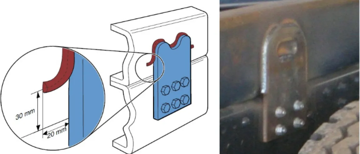
4.3.6 Attachments
Studying several body building companies a few different attachment methods were found. Individual versions of the same solution were common place but the function stayed the same. General for all attachments, or brackets as some call them, are mounting distance set to 600-900mm by Scanias body building directives.In order to obtain a gradual increase in the bending resistance, the frame should be fitted with adapting flexible brackets at its front section, and rigid brackets at the rear.
For a full description of every type of attachment see appendices 8. Rigid weld attachment
The welded support bracket is the strongest attachment method. Only a low amount of movement is allowed and the subframe connects strongly with the chassis of the truck. These support brackets have to be placed at the rear of many tipper body trucks, and should be of the same thickness as that of the side profiles. The number of attachmentsis decided by the selected tipper body. Lower levels of accepted oscillation, requireshigher use ofrigid attachments, like the ones shown in figure 13.
© Mattias Hägglund 30 Flexible attachment
In figure 14 below are two examples of flexible attachments. This attachment-method is longitudinally flexible. That means that it permits some movement horizontally along the frames length. The length and diameter of the screw decides the flexibility of the bracket.
4.3.7 Stabiliser
Some subframe solutions contains something called a Stabiliser. It is a hinged par of profiles that stretches from the subframe up to the tipper body, as shown on figure 15. It is rigid in its construction and helps absorb lateral forces on the tipper body.
Figure 15. Classical Stabiliser (SSAB Database)
Figure16shows a solution that incorporates the hydraulic cylinder into the stabiliser. A benefit of this is a decreased unloading time,making it well suited for truck-configurations where repetitive use is expected. This solution does however reduce the maximum loading weight of the tipper body.
© Mattias Hägglund 31 Figure 16.Stabiliserincorporating a hydraulic cylinder (SSAB Database)
4.3.8 General Directives for Subframe
When constructing a subframe there are directives and recommendations to follow. Some are explained in detail in Scanias Bodywork information documents and others are recommendations from body building companies. During the concept generating and product development phase is it important to keep these directives in mind. Concepts missing or going too far outside these directives will be hard to introduceon the market,and will only havelimited success. This knowledge will help ensure that the product meets the body builder’s requirements.
• One of the subframes roles is to distribute the load evenly over the chassis frame. In order to do this in the best way, a subframe must have the same external width as the chassis frame and must follow its exterior lines.
• The subframe structure may in no circumstances restrict any movement of the tipper body or other moveable parts on the truck.
• Changes in the profile must be gradual in order to avoid high stress points.
• Where possible, the subframes cross members should be positioned over the cross members of the chassis.
• The subframe should it extend forward as far as possiblefor the load to distribute evenly.
• When connecting the subframe with the use of longitudinal screws is it regarded as a flexible connection. Scania recommend that the screw length, diameter and tightening torque is chosen with the designated truck in mind, or the purpose of the attachment may be lost.
For detailed information regarding the subframesdesign see ScaniaBodywork document: Subframe Design.
For detailed information regarding subframe torsional classes see Scanias Bodywork document: Selecting the Subframe and Attachment.
For detailed information regarding subframe reinforcements see Scanias Bodywork document: Reinforcement.
© Mattias Hägglund 32 4.3.9 Centre of Gravity
There is a general agreement that a lower Centre of Gravity (CoG) is affecting the vehicles handling performance and stability. When a truck is fully loaded with 36 tons of payload a height difference of just a few centimetres could make a notable difference. An interview with Björn Jonsson, truck driver for the company DHL, strengthens these thoughts.
-When loading a truck you have to think of how you are positioning the load. Heavy goods should always be placed in the bottom and centre if possible. The way the truck behaves on the road is strongly affected by the position of the load and it´s CoG. This becomes apparent when you for example are driving through a roundabout.
A calculation can be made for the effects of reducing the height of the subframe, which in turn affects the CoG for the payload. This is made in an attempt to scale the benefits of a lower CoG against possible drawbacks.
The values and calculation method is derived from a parallel project where a Scania truck and a new SSAB tipper body are tested. Figure 17 shows what is being calculated.
Figure 17.CoG for loaded tipper body Value1: 2362mm Value 2: 922.5mm ܶܽ݊ ܣ = ଵ ଶ
A = tan
ିଵ2362
922.5
= 68.66
°
A reduction of the height by 50mm or 2.1% would then give:A = tan
ିଵ2312
922.5
= 68.25
°
By removing 50mm from the height of the subframetheangle is reduced by 0.41
°.
Drawbacks following the reduced height of the subframe should be investigated.(Björn Jonsson, Truck driver, DHL
© Mattias Hägglund 33 4.3.10 Tipping Stability
Unloading a tipper body is a critical moment. The CoG is being moved away from its secured position close to the ground. To avoid damage to the truck and its parts unloading has to be done in a correct manner. In the document Roll Stability and Tipping Rollover Stability, Scania explains what interacting factors affect the trucks stability during tipping with the following bullet points:
• Capacity of ground to support the load • Position of centre of gravity
• Roll stiffness of the chassis
• Torsional rigidity of the bodywork
• Stabilising equipment (bogie blockings, empty rear air bellowsandstabiliser) • Practical handling during tipping
Generatedsubframeconceptsshould when possible, work towards the fulfilment of these factors. Unloading a tipper body truck in a sideway hill have proven to be a task associated with damage and injury. As shown in figure18 below, unloading at small angles can be dangerous as well.The risk of tipping over drastically increases withrising angle.
Figure 18. Unloading at angle(National AG Saftey Database)
The best way to test and evaluate how a new construction handles these kinds of forces is through physical testing. Scania therefore provides precise information on how to conduct these tests, see Scania bodybuilding document Roll stability and tipping rollover stability for more information. The recommended angle to perform these tests is set to 5°, this willlater be used during simulation as an angle of reference for the different concepts.
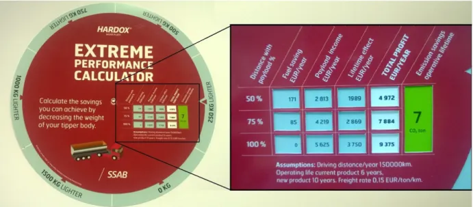
4.3.11 Effects of Reduced Weight
One of the goals of this project is to investigate if the weight of the subframe can be reduced. By reducing the weight several benefits are acquired. Regarding the truck and its lifetime effect, small improvements can provide large benefits. Using SSABs “Extreme Performance Calculator”,an easy-to-read result is given.
If, for example, the weight is reduced by 250kg the lifetime benefits for the owning company and the environment is showed below in figure19.
© Mattias Hägglund 34 Figure 19. SSAB Extreme performance calculator
With increased amount of work performed by the truck the total savings canmoveup to 9000 Euros per year.During the vehicles life time, a total of 7 tons of ܥܱଶ emissions can be avoided. This is a strong argument that can be used during sales of a subframe with reduced weight. Higher payload capacity and fuel savings are numbers that any businessman can understand, something that could defend a possible higher price.
4.3.12 Patent Research
When designing a new product for an international company checking patents on the current area of interest is important. During the concept generating phase of the project a patent research was therefore conducted. This was made in an attempt to find similar or crossing patents.
For this patent check two institutions were used.The Swedish Patent and Registration Office and the United States Patent and Trademark Office. On their respective web sides can a search engine be used to search for active and passive patents.
By searching in their data bases a number of hits could be found. “Subframe” and “Truck Subframe”along with their Swedish translationswere used as the main search words. More than 400 hits were generated and examined for relevant material. Several interesting patents were found but none could however be said to hinder the project in any way. The assessment was made that no concept is in danger of breaking a patent and further development will be seen to avoid it as well.
It should however be remembered that this was only a first attempt to make sure there are no obvious patents in force. As MDH teacher HåkanMattsson so elegantly put it, “that you cannot find it, does not mean it does not exist”. In the future should a wider examination be conducted, preferable with the help from a professional institution.
© Mattias Hägglund 35
4.4
Conceptual Design
Conceptual design is about describing ideas and thoughts with the help of pictures and text. Taking the first steps towards a new product often starts with a sketch on a piece of paper. This project was no exception, ideas starting as sketches on a piece of paper.
During the research and information gathering phase has several different solutions been studied. Some are old and well tested, others are introducing small individual part-solutions. No one of these does however step out of“the box” and approach the problem with new unrestricted eyes. This concept generating phase aims to leave“thebox”, in order to come up with new untested solutions.
4.4.1 Concept Generating Method
This project concept generating phase started with a Brainstorming. With the knowledge previously gathered, numerous solutions or part solutions were generated. Some left “the box” in its design and function and others were improvements on the conventional subframe design. When this no longer proved efficient a Breakdown method was applied. By looking at every part of the subframe individually,newpart solutions could be generated. However, did this only work with the conventional subframe, limiting any major changes of the overall design. This was then followed by using theValue Engineeringmethod. This method is working by identifying and prioritizing the different functions of a product. In the case of a subframe these were: distribute load, connect tipper body to truckand absorb oscillation for example. (creatingminds.org2014.10.26)
As a final effort to produce more concepts and widen thebase of alternatives an in house colleague was consulted.Bo Lindström, Senior Design Specialist at SSAB Oxelösund with many years of experiences could add several new ides to the concept phase. Mr Lindström introduced a couple of previous projects that had some thoughts along the same lines and therefore in turn led to new concepts. He made introductions to additional companies working in surrounding industries, this gave yet more concepts to the project. See appendices 9 for complete concept catalog.
© Mattias Hägglund 36 4.4.2 Concept Groups and Descriptions
All concepts are listed in one of the three concept groups, A, B and C. Group A: Improvements
This group is made up of solutions which aim to improve on the common subframe design. Redesigning the profiles, cross members and attachments can give benefits in the terms of weight, height, strength and production. The introduction of HSS in the traditional subframe design brings possibilities for improvementsworthinvestigating.
A combination of several part-concepts will together result in a complete “group A concept”. Figure 20 and 21 shows a few examples from group A.
Figure 20. Profile concepts and attachment
Figure 21. 45 degree subframe concept
GroupB: Shaped Plate
With inspiration from theKSCspreviously made reports, a number of concepts were generated with steel plate as its focus. All subframes today are built upon closed or open profiles running along the truckchassis. This concept group leaves “the box” by instead utilizing shaped plate. Where needed reinforcements can be added and holes made through the plate.
© Mattias Hägglund 37 Figure 22. Shaped plate concepts
GroupC: SupportConstruction
The third group of concepts approaches the problem differently. The current construction has to be very rigid in order to counter the forces that affect a tipper body during unloading. Because it does this in a very ineffective way, the size and strength of the subframe has to be unnecessarily large. There are today stabilisers between subframe and tipper body to make the tipper more resilient against lateral forces. If this function could be scaled to give a larger amount of support,this could make new and different subframe designs possible.
This group examine if it is possible to reduce the subframe size or even partly remove it by giving better support and counter the forces involved in a more effective way. Figure 23 below shows a number of examples.
Figure 23. Support concepts
4.4.3 Concept Evaluation
To make effective use of time and SSABs resources a concept evaluation was made over Lync together with Jonas Gozzi at SSAB Borlänge. Mr Gozzi, Manager Market Development and R&D at SSAB has experience of working with trucks from previous projects. By making use of his experience aneffective elimination could be made with minimal risk of removing concepts with still hidden potential.
In discussion with Mr Gozzi it was agreed that the most important thing a subframe has to do is to absorb oscillation forces. This follows the same line as the demand specification and Scanias guidelines. Focus will therefore be on the concepts ability to counter these kinds of forces.
© Mattias Hägglund 38 The most common design on SSABs tipper bodies was debated. They use strong top side profiles stretching down in the back to connect with the subframe. The rest is free hanging plate unfit for connection. NoSSAB subframe has any reinforcements on their underside. Concepts with bottom connecting equipment are therefore unrealistic as the tipper bodies would need to be adapted.
Figure24shows a SSAB free hanging tipper body.
Figure 24. SSAB tipper body (SSAB Database)
Many high-end truck manufacturers use a chassis frame that expands in the front, likeScanias trucks does. Concepts must therefore allow for this inflection point in their front most part or be un-affected in its design, seefigure25.