V¨
aster˚
as, Sweden
Thesis for the Degree of Master of Science in Software Engineering
APPLICABILITY STUDY OF
SOFTWARE ARCHITECTURES IN
THE DISCRETE MANUFACTURING
DOMAIN
Dhespina Carhoshi
Ermal Bizhuta
dci18001@student.mdh.se
eba17001@student.mdh.se
Examiner: Thomas Nolte
M¨
alardalen University, V¨
aster˚
as, Sweden
Supervisors: Mohammad Ashjaei
S´
everine Sentilles
M¨
alardalen University, V¨
aster˚
as, Sweden
Acknowledgements
The most important gratitude and appreciations go to the supervisors of our thesis work, Mo-hammad and S´everine, the doors of which were always open for any help we needed. Thank you for the guidance you gave us during this journey together!
I am very grateful and thankful to professor Elinda, for believing in my skills and for making possible all of this! I must express my deepest gratitude to my family, as well, mum, dad and Redushi. Thank you ma. For being my biggest supporter and for encouraging me to always do better. Thank you for always being there in my life and always looking out for me. - Ermal
I would like to express my very profound gratitude to my brother Vasil for supporting me in every step of my life and walking this path with me. I am who I am today just because of you. Thank you! I would also like to thank my mother and my best friend Enxhi for their advice and for being beside me in this journey. - Dhespina
Abstract
Manufacturing, under the umbrella of the latest industrial revolution, has gone through enormous changes in the last decades to then later evolve in what we know now as smart manufacturing. Different companies and entities have developed their own versions of architectures for intelligent and digitalized manufacturing systems. Ideating a flexible and safe architecture is one of the first steps towards a system that intends to be applicable in different environments, regardless of the vast variety of possibilities available. For this purpose, the following thesis presents an investigation on the state-of-the-art solutions of the most recent digitalized cloud-based system architectures in the domain of discreet manufacturing. Based on an initial system architecture conceived from the company ABB, an evaluation of this architecture was conducted, by taking in consideration the existing systematical approaches to the digitalization of this industry. In the following thesis work, we investigate, describe and evaluate the limitations and strengths of the most recent and known architectural approaches to cloud robotics. Finally, a few key remarks are made towards ABB's initial solution but also to the industry in general.
Table of Contents
1. Introduction 1
1.1. Problem description . . . 1
2. Background 3 2.1. Cyber-Physical Systems and the Cyber-Twin . . . 3
2.2. Cloud computing . . . 3
2.3. Internet of Things (IoT) . . . 4
2.4. The system architecture proposed by ABB . . . 6
3. Method 9 3.1. Determining aspects of architectures . . . 9
3.2. Standard procedures of assessing architectures . . . 11
4. State of the art review 14 4.1. Previous applicability studies and related work . . . 14
4.2. State of the art solutions . . . 16
4.3. DAvinCI . . . 16
4.4. ROS - Rapyuta and RoboEarth . . . 18
4.4.1 Communication Protocols . . . . 18
4.4.2 Basic Communication Example . . . . 19
4.4.3 RoboEarth in a nutshell . . . . 19
4.4.4 The Rosbridge layer . . . . 20
4.5. McCormick Research . . . 21
4.6. Temboo's Architecture . . . 23
4.7. KUKA . . . 24
4.8. Hirebotics - Universal Robots . . . 26
4.9. Comau . . . 27
4.10. Yaskawa . . . 29
5. Analysis of the research and observations 31 5.1. The clutter with robot programming languages . . . 34
6. Case study analysis 35 6.1. Case study selection . . . 35
6.2. Methods of approach to the case study and observation records . . . 36
6.3. Results of the approach . . . 36
6.4. Applicability of the case study . . . 36
7. Major research implications and future work 38 7.1. Conclusions . . . 38
7.1.1 Answers to the research questions . . . . 38
7.2. Limitations of the thesis work . . . 38
7.3. Future work . . . 39
List of Tables
1 The architectures of PADME’s solutions . . . 7
2 Observations on the architectures . . . 32
3 Applicability study . . . 37
4 Researched areas and their results . . . 39
List of Figures
1 The system architecture of robots operating via cloud from Wan et al [1] . . . 42 Sensors and actuators that allow connectivity inside the IIoT architectures . . . . 5
3 An IoT system has a three-level architecture; devices, gateways and the data system [2] . . . 5
4 Information modeling of the OPC UA [3] . . . 8
5 Utility tree of the architecture's attributes . . . 10
6 The Domain Architecture Comparison Framework (DACF) [4] . . . 13
7 A simple robot control system . . . 17
8 DAvinCI's Web Engineering Framework [5] . . . 17
9 A simple robot control system. . . 20
10 Rosbridge's system architecture [32] . . . 21
11 A three-cell manufacturing system with shared resources on the network [6] . . . . 22
12 Components of the network layer of McCormick [7] . . . 22
13 McCormick's proposed architecture [6] . . . 23
14 Temboo visualization application showing the level of water. [8] . . . 24
15 Temboo's simplified architecture. [8] . . . 24
16 KUKA's System Architecture . . . 25
17 KUKA's Robot Communication . . . 26
18 Hirebotics' simplified architecture . . . 27
19 Comau's system architecture before ROS integration. [9] . . . 28
20 The developed system including initial structure (red) of Comau using ROS. [9] . . 28
21 Yaskawa's system architecture. [10] . . . 29
22 An improved machine controller by Yaskawa. [10] . . . 30
1.
Introduction
During the last few years, many researchers have paid special attention to Industry 4.0 and Smart manufacturing. This recently introduced term includes everything from digitalized and automated warehouses, logistics, renewable energy, resource industries and healthcare to smart cities. Indus-try 4.0 fosters the digitalization of companies and factories by utilizing machines and equipment virtually connected to be able to monitor and manage the processes of production. Smart man-ufacturing, a constitutive part of Industry 4.0, has been defined as the set of interconnected and collaborative manufacturing systems that respond in real time to the needs and conditions in fac-tories, in the supply network, and in customer requirements [11].
This development comes with a rethinking of the companies' strategies and their investments, which means a total change in the company's operational and business models; eventually resulting in the need for further investigation on the new frameworks to be adapted. There is an aboundant amount of research on the specific technologies and approaches that involve Industry 4.0 due to the continuous development of the area, but there is still a large amount of scientific research to be done to be able to give companies assurance of what they need to change and update in order to adapt to the digital environment. One of the approaches has been the one of the automation multinational company ABB, which can be easily taken as a good example of how the benefits of this development can be obtained [12].
The focus of this thesis is the evaluation of different solutions of digitalization in the automated manufacturing industry, by analysing and reporting key remarks that can lead to further investiga-tion about them. Furthermore, the other focus of the thesis is assessing the applicability of ABB's proposed solution through the PADME project (Process Automation for Discrete Manufacturing Excellence) in the reference company, which we chose to be GKN Driveline. Most of the concepts that we will focus on, are terms like Industry 4.0, Smart Manufacturing, Cloud Computing (CC), Industrial Internet of Things (IIoT), Cyber-Physical Systems (CPS), and Cloud Robotics, which are detailed further later in the thesis.
1.1.
Problem description
There is an enormous amount of opportunities available with the digitalization of the discrete man-ufacturing domain. However, most industrial production has legacy systems that are not easily exchanged and strict requirements, much tougher than for consumer product, creating multiple challenges when it comes to implementation. Although the end goal is to have a complete overview of the discrete manufacturing process similar to how it is done in process industry - a stepwise approach, first providing the overview for selected sections or even only functions is advisable.
In discrete manufacturing, the final outcome of all processes is distinct and countable items, such as cars in the automotive industry, as in contrast to the continuous production in process industry where output could be a liquid like oil. Since latency in the systems is difficult to manage and overlook, an approach that is able to alarm and reduce those latencies in the processes is needed, so factories behind production can solve failures and adopt solutions as fast as possible. But most of the time, the process of overlooking through failures and proper functioning of the system is done with a human in the middle. In most of the cases the human can look into different pieces of information from different components of the isolated islands in discreet manufacturing. This information in most of the cases, is not in any way connected with each other. This makes it difficult for the factory involved in the process to subtract useful data reusable to analyze the defects in the processes. The main approach for this kind of problem is digitalization. How-ever, to achieve effective digitalization in discrete manufacturing, the main step is to first build a system whose architecture can provide possibilities to simulate, analyze and better manage the production system and allow communication between the isolated islands of information. The architecture describes how the technologies relate and connect with the production equipment on the factory floor, more specifically, the set of interfaces, modules, components, and all the associa-tions between them that make all the services possible, constitute the system architecture [4]. The
way the system architecture is composed and how its components behave when connected are what make systems differ from each other, with architectures having their own characteristics that define different attributes of functionality, reliability, usability, efficiency, maintainability, and portability. In this thesis, we have conducted an applicability study, which in other words means to con-duct an investigation of the architectural systems found in existing literature; research studies; and projects, outline their specifications and examine the applicability of our case study to them. This will lead us to come up with research that not only investigates a real-life example of a system architecture, but with a proper outlook of the benefits and limitations of each analyzed system At the moment, since the topic of digitalization in discreet manufacturing is quite recent, there are few solutions with no standard and generic industry accepted solution. This thesis work aims to investigate the available solutions and study the applicability of them on different companies. ABB Corporate Research and ABB Control Technology in V¨aster˚as proposed an architecture in this domain within the PADME project, where its applicability will be investigated and evaluated during the thesis work [13]. The available architectures that included in the PADME project [14] lack proper evaluation in terms of consistency and adaptability with existing projects and their compatibility with technologies in other companies, so the main ambition of the project will be to evaluate the possible applicability of the ABB proposed architecture in other domains other than ABB itself.
During this thesis work, the following questions will be answered:
• What are the state of the art solutions on digitalization in the discrete manufacturing domain? • What are the characteristics and limitations of the proposed architectures in comparison? • What are the challenges in terms of applying a digitalization architecture on different
do-mains?
Furtherly, we take an in-depth look at the ABB's proposed solution through the project PADME [15], its applicability in other domains and evaluate the results. This thesis is relevant to digi-talization since it brings an insight into a tool with considerable importance in the Industry 4.0 domain and it focuses as well on architectures which are developed for realizing the manufacturing digitalization. To do so we start with reviewing and investigating the existing architectures in various domains. Then, we compare the architectures according to attributes, such as reliability, availability and security. This evaluation gives some insight about different aspects of the pro-posed architecture. Moreover, in this thesis we present the recent solutions which were developed by ABB Robotics via the project PADME [15]. We also investigate the practicality of using the same architecture on a different discrete manufacturing company than in ABB Robotics to present the applicability and limitations of the architecture. The comparison and evaluation of the archi-tectures can be used from manufacturers which are still doubting on the otucomes of a system migration of the processes into a fully digitalized solutions with features such as data visualization, cloud integration and predictability of errors.
The remainder of the report is organized as follows: The first section of the thesis introduces the reader to the formulated problem and the goals which the thesis aims to achieve. In Section 2, we have explained the key concepts which are commonly mentioned throughout the thesis and are needed to be understood in order to be able to follow the thesis work and to properly capture the digitalization and architecture terms. In the same section we have described the system architectures proposed by PADME which are the case study of the work. Section 3 outlines the research methodology and the approach used to conduct the thesis work. Section 4 gives an overview on other applicability studies related to our work and the state-of-art of this topic, by identifying existing researches and the specifications of each architecture being investigated. Section 5 contains the analysis of the research and our observations about the evaluated case study can be found in Section 6. In the last section of the thesis, Section 7, we outline the main and results of the research and the limitations of our work, together with a discussion about the research questions and future work to be done on the topic.
2.
Background
Industry 4.0 consolidates embedded production systems with intelligent production processes and is radically transforming industry production chains, especially discrete manufacturing of products. All electronic systems that perform a specific function and collaborate inside a larger system, by combining together software and hardware, fall under the term of ”embedded system” [16]. Em-bedded systems are by all means subject to the modernization of the manufacturing systems to a higher intelligence level with every data about physical processes and information flows available at any time needed, as they make the basis of every manufacturing system.
Even if these systems are effective in fulfilling their main objective, intelligent manufacturing still requires certain supporting technologies to allow devices or machines to specify their behavior in different situations and requirements, apart from embedded systems. These technologies, like cloud robotics, are part of an advanced manufacturing model that functions under the support of cloud computing, Internet of Things (IoT), virtualization and sometimes artificial intelligence techniques. The technical aspects of these needs have been previously generally addressed with the application of concepts like Cyber-Physical Systems (CPS) and the industrial IoT (IIoT), explained below in this section. These services allow a modern interpretation of data via decentralized control and advanced connectivity by giving companies the opportunity to extract information that can be tracked, monitored, shared and can further optimize the functionality of the manufacturing system in real-time. Below we have explained some of these key concepts which are commonly used throughout the thesis.
2.1.
Cyber-Physical Systems and the Cyber-Twin
With the help of Cyber-Physical Systems (CPS), we can oversee interconnected frameworks [17] between a system's physical resources and computational capacities. This term integrates com-putations with physical processes. Information about manufacturing components (machines and robots) and their corresponding modules are connected virtually by cloud to get synchronized. This virtual rendering of physical components is often termed as cyber-twin of that component in the system. The CPS manage big data through the inter-connectivity of manufacturing compo-nents to achieve the goal of intelligent, resilient and self-adaptable compocompo-nents. When the sensory data from the physical resources are extracted and converted into manipulable data, a cyber-twin of each component is responsible for capturing time machine records and recreating future steps to provide self-awareness and self-prediction for the system. The cyber-twin of each component allows CPS to provide intelligent capabilities in different sectors of the system's architecture, thus allowing the system to become self-configurable and maintainable. This level of computing provides optimized production and planning for factory management [18].
2.2.
Cloud computing
PADME's main aim is to have a factory environment that would sustain all processes of digital man-ufacturing by cloud-connected robots in an automatic way. Digital manman-ufacturing takes advantage of cloud computing frameworks since a cloud-based platform can be ideal for integrating different business entities and locations and extending integration to suppliers and customers.Technologies, such as Cloud Computing, Simulation and Data Analytics, promise to deliver these benefits. Cloud computing is a set of services that enable access to distributed and shared computing resources over the Internet, including information processing, information storage and massive data sets. Cloud computing interacts with robots by offering them higher computational abilities through greatly parallel calculation and information storerooms.
Cloud robotics [19] is a term used for cloud solutions and robotics, part of an architecture that mainly consists of two componentsthe cloud infrastructure and the automated robots and equipment. The cloud infrastructure consists of many high-end servers and large databases able to handle processing and computation of industrial speeds. In Figure 1, the architecture above and all components of a cloud robotics system are presented.
Figure 1: The system architecture of robots operating via cloud from Wan et al [1]
2.3.
Internet of Things (IoT)
Internet of Things (IoT) is a crucial part of the use case of the thesis work, as GKN and the system architecture of PADME overall make use of sensors so to exchange information between components of the architecture. IoT relates to robotics through the use of nodes, which then make possible the creation of IoT sensors, devices and platforms [20]. These nodes interact on a cooperative basis and are, in most cases equipped with a variety of sensors, as shown in Figure 2, that enable them to collect signals and data from them. In this way, with features like deployment of sensors, easy cloud connectivity and data analytics improve asset performance, IoT enables the integration of all pieces of smart connected machines with the wider enterprise. IoT also enables employees to use mobile devices for features like data analytics, augmented reality and transparent device inter-connectivity. In Figure 3, we can see all the possible components of an IoT system and their communication connection. The architecture uses wireless sensors connected to the network, where the data is transferred from node to node through each sensor. The edge node serves as a gateway between the wireless sensor network and the internet, and the best part of using it is that it can provide local storage and have a user interface. The IIoT architectures are usually composed of a large number of connected sensors and actuators spread in wide areas such as factories or even environments like windmill fields.
Figure 2: Sensors and actuators that allow connectivity inside the IIoT architectures
2.4.
The system architecture proposed by ABB
The base architecture that will be used to perform the applicability study will be the one from ABB. Its solution is an architecture, the pinnacle of which is the inclusion of the ability for analysis, monitoring and controlling of processes [14]. The processes happen inside the cell, a term used to refer to the altogether of components that are the robotic hand/controller, the Programmable Logic Controller (PLC), the nut runner (used for loosening and tightening physical components) and the oil filling system. The components of the cell are connected with the 800xA, which is a distributed and electrical control system with the capacity to improve the overall efficiency of systems through operator performance and asset monitoring. The operator interacts with the 6-axis robot controller and the AC500 PLC with three Safety IO modules and two non-safe modules through the Human Machine Interface (HMI) application with its specific communication protocol. In the architecture, all production cells are connected with each other, and the visualization of the information is possible inside the cell and is made possible from the data collected through the 800xA, which provides at the same time the data required for the simulation and analytics application (SAAP) [14]. The architecture proposed by ABB comes with several versions that differ from each other by their type of connections and ways of information storage, but the main rationale of the architecture is that the components in the cell mentioned above store their data in a local database. Therefore, apart from this version of the architecture with direct communication between components, ABB has introduced two other solutions1:
• ABB Ability solution with Edge-to-Edge communication
In this architecture, an indirect approach is used by using Edge to pull data form the robot, while for the communication of the SAAP with the 800xA system a cloud-based approach is suggested, where the data is made available on cloud storage through different cloud services. The data from the robot is pulled into the PADME Robotic Ability Edge (a concept of an ABB Ability framework) through an Edge-to-Edge communication protocol. To send the data to the 800xA and Ability cloud an Ability infrastructure is proposed, and information collected from other components such as PLCs, nut runners and the oil-filling systems goes through Edge directly to the Ability cloud.
• Simple ABB Ability Solution
For the successful communication of the SAAP with the 800xA system, ABB ability frame-work is again used. In this solution, data is pulled from the robot to the 800xA system through the direct approach of using the OPC protocol and OPC server, which will be ex-plained in the subsection below, as this protocol is a relevant factor of ABB's architecture. This approach supposes the OPC server, and a special instance of that classic OPC server specifically developed for that robot controller to be implemented in the robot side of the architecture. This solution imagines as possible using another alternative that would pull data directly from the robot through a Robot API, which would, in this case, be required to be equipped with a data access API to be developed within the 800xA node.
• Database Solution
This last architectural approach differs from the others from the communication type of the SAAP with the 800xA system. ABB has suggested the use of a local database, more specifically a Mongo one. A direct approach with an OPC UA protocol is suggested for transferring the data from the robot to the 800xA system.
For a better understanding of the components and connectors of the architectures, we have represented the solutions from ABB in Table 1.
• OPC Unified Architecture Protocol
The OPC, OLE (Object Linking and Embedding) for Process Control is a software interface standard that allows computer programs to communicate with copious industrial equipment [3]. The OPC Unified Architecture, in short OPC UA, is the communication protocol profile based on the OPC, it is widely mentioned in the thesis as it is the main protocol used for the
communication of the components in the PADME system architecture of ABB. OPC UA is an open platform, compatible with several operating systems and programming languages, that allows information exchange between industrial systems and its further manipulation and use [3]. OPC has been the choice for being the main communication protocol of PADME since it has remarkable compatibility with existing systems, it is secure, extensible and can easily be integrated into most platforms [3]. Below, in Figure 4, we get a brief overview of how OPC UA works; as we can see, the information modeling that OPC UA has allows it to be operable and changeable according to the vendor that intends to make use of the protocol, by appropriating data types and structures in specified profiles by the vendor.
3.
Method
In order to successfully perform the research, first, we needed to conduct a proper literature review to find other studies similar to ours, which gave us results that we describe in the next section of the thesis. After the literature review, we conducted a set of visits at ABB where we had a close approach with the system and architecture and after that a case study at one of the partner companies of the project, following steps suggested by Wohlin et. al. [21]. These steps describe how the work should go through five major processes when evaluating and conducting a case study, as follows:
1. The case study is designed and planned according to the decided objectives from the re-searchers.
2. Procedures and protocols for data collection are defined prior to the collection of data. 3. The case study is conducted while constantly collecting data on the case being studied. 4. Collected data is thoroughly analyzed.
5. After being analyzed, the data is reported.
The goal of the case study is to help us better understand how the system works, discuss our concerns with the people involved in the project and last evaluating the applicability of the system in the other company. The visits to the companies provided us with answers and insights, which helped us in our research. To conduct the applicability study most efficiently, we are going to make use of the guidelines [22] on how to do an evaluation of system architectures in software engineering, which consider attributes that define the system's quality such as performance, security and modifiability. Further assessment was used to evaluate how the architecture's components (modules, objects, processes, subsystems, units) communicate inside the system. The assessment includes relevant relations such as calls, sends-data-to, synchronizes-with, uses, depends-on and instantiates [22].
3.1.
Determining aspects of architectures
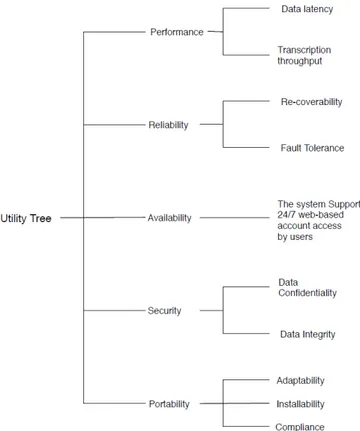
A system architecture of discreet manufacturing processes, to be able to satisfy the consumer re-quirements, must have high reliability, security, availability but not only, as shown in Figure 5, regardless of its type and application domain. Due to the nature of our case study, the attributes which we are able to draw out so to make the comparison and evaluation are mostly the security and type of the architecture and its functionalities, which are determined by the key technologies they make use of. Below we describe these two most important factors that were targeted in this thesis.
Figure 5: Utility tree of the architecture's attributes 1. The type of architecture and its functionalities
Different types of architectures are available in the industry nowadays, but the resemblances that they have with each other allow us to categorize them into several types, as seen in [23]:
• Service-Oriented Architecture • Network Architecture
• Infrastructure as a Service (IaaS) and Virtualization Architecture • Robotic and Embedded System Architecture
• Online and Offline system of Cloud and Robot grasping architecture • Cloud and IoT Architecture
The functionality of a system architecture is determined from the decomposition of its interface [14]. In this thesis, the decompositions of the architectures being evaluated differ mostly from the components being used and the connections between them. Therefore, in the upcoming sections of this thesis, it will be demonstrated that aspects such as the key technology and the patterns of communications between components, connectors and modules of the systems, being indicating factors of how the system functions, are the basis of the applicability study.
2. The security of the architecture
Security is one of the main focuses of the architectures, especially in the case of the architecture of PADME, where solutions which are safer (local database) are selected instead of ones that might offer a faster access but with questionable security (cloud services) [14]. Most of the data which is transferred over the network and is used to interconnect the smart factory is necessary to be adapted to the right cyber-security measures on the network. Apart from virtual layers of security, physical security of each device is also important, since hacking a device within the factory would ultimately lead to a compromised network with device malfunctions.
3.2.
Standard procedures of assessing architectures
The architecture of a system is the design software development that addresses the quality goals such as security, reliability, usability, modifiability, stability, and real time performance [24]. It is of crucial importance for the success of a system, and it is a standard part of the development cycle. In order to assess an architecture, several standard procedures and methods have been proposed and are in use. In the methods described in Section 2, it is mentioned that an evaluation can be applied at any stage of an architecture lifetime. The evaluation of an architecture begins when the architecture is known but the implementation has not started yet [4]. The evaluation of the architectures and their specifications will be made according to the steps proposed by Gampa et al [25] used in almost all of the following proposed methods for the evaluation of the architecture [25]:
• SAAM - Scenario-based software architecture analysis method. • ATAM - Architecture-based Trade off Analysis Method
• ALPSM - Architecture-Level Prediction of Software Maintenance • ALMA - Architecture-Level Modifiability Analysis
• SBAR - Scenario- Based Architecture Reengineering
• SALUTA - Scenario-based Architecture-Level Usability Analysis • SAAMCS - SAAM for Complex Scenarios
• ESAAMI - Extending SAAM by Integration in the Domain • ASAAM - Aspectual Software Architecture Analysis Method • SACAM - Software Architecture Comparison Analysis Method • DoSAM - Domain-Specific Software Architecture Comparison Model • CBAM - Cost Benefit Analysis Method
• FAAM - Family-Architecture Analysis Method
We have chosen to do the evaluation of the architecture with the following three methods SACAM, ATAM and DoSAM, since their structure and the steps involved in each of them are the most suitable for discreet manufacturing system architectures, and our case, considering that in our applicability study we do not take in consideration factors such as cost-benefit and com-plex scenarios. Furthermore, the architectures to be evaluated are not only software-based so the majority of the evaluation types cannot be used. The first two evaluation methods (SACAM and ATAM) take on a more general approach to the comparison of the architectures, while the last one DoSAM allows us to look more in detail to the specifications of the system. Hence the evaluation then tackles aspects that account for most of the weaknesses and strengths of the system.
A. Software Architecture Comparison Analysis Method (SACAM)
The Software Architecture Comparison Analysis Method was created to provide a ground sys-tem to use when selecting an architecture that will best suit a syssys-tem. It is the most suitable method of evaluation for architectures of the same domain [4]. The SACAM compares archi-tectures by taking in consideration the business goals of the organization proposing the specific architecture. In our case, we can say that all the architectures have a common business goal, a system that will be smart, automated, cost efficient prone to be always up-to-date and that will continue to be relevant when future technologies take place in the organizations adapting the ar-chitectures [4].
To evaluate the architectures via SACAM, we make use of SACAM's indicator system to determine the criteria architectures are compared with. First, architectures need to be analyzed so to identify the criteria and then prioritize the most important ones with the most prominent influence on the evaluation. The architecture's style, design, complexity and patterns regarding components and elements are concrete indicators that capture key quality attributes of the system like performance, availability, modifiability and security. In our case, as indicators for all the evaluation methods, we will evaluate the following architectural aspects [4]:
• Topological evaluation (the architectural style used).
• Components(e.g. modules, objects, processes, subsystems, compilation units, and so forth) which document the different units of the architecture, address the modifiability of the system. • Connectors (e.g. linkage between modules, connections across the network, configurations
of server addresses) which document the concurrency behavior of the architecture.
• Patterns of communications between components, connectors and modules in our case, it documents the different ways that the units as mentioned above communicate with each other and exchange information
B. Architecture-based Trade off Analysis Method (ATAM)
The focus of this evaluation method is finding crucial tradeoff decisions of the architectures and detecting contingencies that might negatively affect the system by highlighting at the same time a variety of attributes such as modifiability, portability, extensibility, and integrability [4]. By evalu-ating the implications of each trade off this method also gives insight on the quality attributes by exploring the different interactions and the interdependencies mechanisms between them. There-fore, ATAM aims to show that architectures satisfy the requirements efficiently. This method consists of four main phases: Presentation, Investigation and Analysis, Testing, and Reporting [4]. The phases their selves contain several sub-steps to follow while conducting the evaluation: Presentation Phase
Step 1: Understanding ATAM and how it is executed Step 2: Identifying business drivers and goals
Step 3: Analyzing the whole architecture Investigation and Analysis Phase
Step 4: Identifying architectural approaches and trade off points Step 5: Generating the utility tree of quality attributes
Step 6: Analyzing the approaches Testing Phase
Step 7: Brainstorming of properties and their prioritization Step 8: Reanalyzing and comparing the architectural approaches Reporting Phase
Step 9: Presenting the final results
C. Domain-Specific Software Architecture Comparison Model (DoSAM)
The DoSAM method compares system architectures by referring to a framework that makes possible the evaluation of systems of the same application domain [4]. The framework consists of the domain architecture blueprint (the architecture's design and style) and the services which are offered by the architectures. We chose this as the third evaluation method, since all the archi-tectures we have chosen as cases to review are all a part of the same domain, the one of discreet manufacturing. Although DoSAM is restricted into evaluating only architectures of the same do-main, this method allows us to localize constituent components, which are virtually present in every solution that is going to be compared [4].
In DoSAM, evaluation is performed by taking each quality attribute of the system architecture and pairing it with the attribute special metric, which represents that attribute. In our case, an example of how this pairing is done is the architectures' security as a quality attribute and the data storage service serving as a metric for it. In the Figure 6, we can understand schematically the logic of this evaluation method by viewing the framework of comparison (DACF) which makes the DoSAM evaluation possible.
Figure 6: The Domain Architecture Comparison Framework (DACF) [4]
The framework of the architecture domain comparison requires the evaluator to first under-stand the blueprint of the architecture, identify the services and goal of it, and then after obtaining the metrics needed to assess each attribute to then evaluate by using computational techniques based on weighted values when they are available or by performing an evaluation based solely on the nature of the metrics being compared [4].
4.
State of the art review
In this section we are going to summarize the works related to out applicability study, and then present the state-of-the-art solutions that correlate to the case system architecture being studied in the thesis.
4.1.
Previous applicability studies and related work
At first, we started the literature review by searching with the terms that define a broad cate-gory of smart factory solutions. The literature was executed in online databases such as Google Scholar, Google and research databases like IEEE, Springer, ResearchGate, by searching with terms that characterize a general class of smart factory solutions. We analyze the key technologies like Collaborative Process Automation Systems (CPAS), Industry 4.0, IoT, Big Data Analytics (BDA), Cloud Robotics, System Architectures, Communication Protocols. Topics that we investigate are related to digital approaches in discrete manufacturing and alternative solutions to ABB's in smart factories.
Although, some of the papers we reviewed provide just a basic overview of collaborative man-ufacturing management systems and how these systems support integration and communication across the manufacturing value chain. This lead us in discarding those results, as they describe the process of digitalized manufacturing in the big picture of the supply chain and do not give an in-depth review of the architecture the system uses. It is important as well to outline that to find some of related works for this project we needed to explicitly remove the term architecture and applicability at times, since some cases did not consider the blueprint as an architecture of components, but more like the workflow of processes of one component (mostly the robotic arm) and how it communicated with the other remaining parts.
The related works to our thesis consist in researches on the applicability of one specific service or framework or analysis which compare real-life approaches from a comparative point of view of several architectures.
In 2016, Bouziane et.al [26], by using web service technologies, demonstrate the applicability of a ROS-based approach (ROS is furtherly explained in section 4.4 of robot as a service in cloud computing. They have implemented a solution that fits the ROS technology in an architecture compound from a robot controller which is managed via a Java web interface and ROS messages. The solution consisted in the hypothetical addition of a communication layer between the robot and the provider, but still lacked the future step that would see the solution implemented in the different levels of an architecture and on a real robot as well.
In 2013, Jordn et.al [27], present a roadmap for the future development of emerging application areas of cloud robotics applications. The current status of collaborative process automation systems is described in the paper, alongside with remarks on how the rising applications of cloud robotics are categorized depending on their use in the industry and their applicability area. The paper presents an application-idea for a Facebook for robots, where robots will supposedly make use of centralized data able to evolve cognitively through the robots reasoning skills and through the continuous usage of open-source platforms. The
Kehoe et.al, through an extensive survey of 150 participants on cloud robotics and automation, in [28], define the different solutions available in the industry and their possible applicable envi-ronments, by also taking in consideration the limitations of their applications. The aspect of the applicability of systems in time sensitive environments is also mentioned, since some applications have real-time demands and systems based on cloud can be prone to network flaws such as latency, bandwidth and quality of service [28]. Another aspect that Kehoe et.al mentions as important for the applicability in real-life domains, is the security aspect of hacker attacks with the goal of disrupting the functionality of the systems. Both Bouziane [26] and Kehoe [28] emphasize the im-portance of the security aspect when mentioning cloud, due to the nature of wireless infrastructures and the criticality of the information being exchanged in the systems.
Doriya et al analyzes several existing architectures within the cloud robotics area [29]. Apart from outlining the challenges that come when applying the architecture, the authors propose an architecture (which is named as a framework in the paper) that would overcome the security flaws aspect of the system and would shield every service inside a cloud-enabled robot architecture [29].
The authors investigate on several system architectures which are a case subject of this thesis work as well, such as RoboEarth, Rapyuta, DAvinCI.
In 2017, Yaguchi et al present a research which focuses on robotic cooperation on a bigger scale, which would supposedly affect several areas of the human's life like disaster management and manufacturing [30]. This cooperation sees the applicability of their suggested framework in cases where robots can create a common knowledge base out of their native architecture where they would pull data for their behaviors and issues. The paper mentions that the architecture of a system matters less than the applicability of the architectures when faced with the multiple challenged in real-life implementation, such as the quality of the service, namely latency, energy issues, safety and communication issues [30].
In 2018, Dawarka and Bekaroo in [23] investigate and compare existing cloud robotic archi-tectures to identify their limitations and future work that needs to be done in that field through the evaluation methods used by Hu and Tay in [1]. In the paper it is acknowledged that the majority of the current state of art reviews about cloud infrastructures and robotics are mostly hypothetical and non-implemented in real life examples, making them questionably feasible. The author has gathered information from previous methodologies and researches and has classified the architectures like mentioned in section 3.1 of this thesis.
These methodologies summarize all the possible types of cloud-based robotic architectures, which are:
A. The architecture proposed by Terrissa and Ayad Service Oriented.
In this architecture the system is composed from two parts, the client and cloud side, which have an integrated Virtual Robot Layer that can manage the robot and virtualize it through its cyber-twin through web services [31]. On the client side the architecture consists of a Client Administrator, Cloud Administrator and Cloud Robotics Administrator, which operate on the Virtual Robotics layer of the architecture [31]. The architecture proposed from McCormick, which is discusses in section 4.6, follows the same principles as this architecture.
B. The architecture proposed by Wan et al.
Wan et al views a cloud robotics architecture made from two parts, the cloud infrastructure, as shown in Figure 1, where all the computing is processed, and the robot part [1]. This architecture proposes all the computing processes to be performed in the cloud so to be able to unload the robot from most of the tasks, with its management being done over cloud therefore resulting in less loaded robots with longer battery life and less possibilities of issues and flaws [32].
C. The architecture proposed by Mouradian et al.
Mouradian et al proposed an Internet of Things Infrastructure as a Service (IaaS) architecture for robots to be able to upstream applications as a service [33]. This architecture is composed of four main layers, them being the Network-Level Virtualization Layer, Node-Level Virtualization Layer, Physical Layer and Gateway Level. The top layer of the architecture is the layer which interacts with the IaaS made of sub-layers like the Publication Engine and Robot Monitor, while the Node-Level layer is made of the cyber-twins of the robots [33]. With this set of layers, the system is able to support several communication protocols and application programming interfaces (APIs) through the Gateway Layer, which gives an architecture extra flexibility and benefits due to multiple ways of robot adaptations.
D. The RoboEarth system architecture.
The RoboEarth system architecture is extensively described and analyzed in section 4.4 of the thesis.
E. The Cloud-Based Robot Grasping System Architecture by Bekris et al.
In this architecture by Bekris et al [33], which is specifically created for the grasping behavior of the robot arm, the system consists of an online and offline status and makes use of several Google services. When offline, the system sends Computer Aided Designs (CAD) to the Google Cloud storage. Through the Google Object Recognition Engine, the system is able to save the
specifications of the CAD and then identify the object with 3D sensors that allow the robotic controller to successfully perform the grasping of objects. When online, robots are finally able to store the log of their processes and behavior in the cloud server for later reference.
F. Service-Oriented Robot-as-a-Service (RaaS) Architecture .
The Service-Oriented architecture (SOA) described in [23] that views the Robot as a service consists of three blocks; the RaaS unit, the RaaS cloud and the devices which hold the SOA interface. Through the RaaS unit customers can access a repository of possible libraries and tools for their needs, while the cloud holds different applications implemented in the units. G. IoT-based Cloud Robot Architecture.
The last type of architecture is IoT-based and is ROS-based [23]. It consists of the cloud layer, the ROS nodes and the IoT enabled objects. The cloud layer offers access to modules such a Web Dashboard and Data Lake storage, while the ROS nodes act as integrators and controllers for the cloud layer and the IoT enabled objects.
4.2.
State of the art solutions
After analyzing results obtained, we found papers that provided theoretical researches on the topic, like the paper written by Martin Hollender and ABB engineers Collaborative Process Automation Systems [14]. The paper is based on the book with the same title by Hollender [14], where he presents a complete overview of the state of the art in CPAS by explaining the systems and right infrastructures needed for the well-functioning of collaborative automated systems. CPAS. The paper is written by researchers who work at ABB and emphasizes the position ABB has in this sector, by highlighting the OPC Unified Architecture (OPC UA)2and its effectivity when connected
with ABB's 800xA device, a crucial component of our case as well. This work mentions several benefits of using the OPC UA protocol for its flexibility, capabilities and security. However, to broaden the horizon of the searched papers we focused more on articles using approaches different than the standardized OPC UA. The authors in the papers mentioned above believe that OPC UA with its extensible modeling potential is well suited as a communication technology in this field of manufacturing automation.
The most relevant works related to the topic of our research are the RoboEarth project [34], the McCormick research [6], TEMBOO, the solutions offered by the company KUKA [35], Comau, Yaskawa. Due to the big amount of related works, we disregarded papers that only described the behaviors of the robot controller, and did not give any insight on the inclusion of the robot in any kind of architecture, like the cases of Kawasaki and Fanuc (both based in the production of the robot controller only), Stubli (no relevant information for the study found). In those cases, the only information or papers that could help our investigation were papers that described the collaboration of the robot controller with other systems, most of the time hypothetical structures that did not go in detail into any possible architecture the robot could fit in, but briefly describing processes vaguely such as the one in the figure below.
The applicability study would not have been possible if analyzing architectures just by a sim-plified overview of the architectures like in Figure 7, since it would not give us any detailed infor-mation about communication protocols and other components. Hence, the system architectures that we will describe and evaluate in the subsections below will be the ones shown in Rapyuta: The RoboEarth Cloud Engine paper, TEMBOO's website, DAvinCI Operating Systems for Cyber-Physical Manufacturing paper, the KUKA-DLR Lightweight Robot arm paper, Hirebotics, Comau and Yaskawa's website.
4.3.
DAvinCI
DAvinCI is a software framework for the management of service robots not only in discreet man-ufacturing, but also in environments like office building, airports etc. It is designed as a system that contains three sections, as shown in Figure 8: the DAvinCI Architecture Layer, the DAvinCI
2OPC Foundation Website https://opcfoundation.org/about/opc-technologies/opc-ua/
Figure 7: A simple robot control system.3
Modeling Framework and the DAvinCI Runtime Library. Its architecture is based in computation, with the main focus on using cloud to establish the connection between robots. The DAvinCI Mod-eling Framework provides a rich set of Computer-Aided Software Engineering (CASE) tools, which automate the modeling process and connect it to the Graphical User Interface, together with the database design and the application logic, which is done by using the Unified Modeling Language (UML). The main difference between the Web Engineering frameworks is the architectural concept of DAvinCI, which is described in the DAvinCI Architectural Layer, as shown in Figure 8. The architecture depends on the presumption that, for a Web application the hypermedia paradigm is not very suitable. The hypermedia paradigm says that an established web site depends on URLs, hyperlinks, and different sorts of assets which is the essential idea of hypermedia systems like the Web. That is why when DAvinCI was developed the main idea was to eliminate that paradigm and to add an extra layer between a servlet container and the application. A servlet container is an application server that is used to implement programming models to write components like servlets, process HTTPS requests through a version of the Java Servlet Specification [5].
Figure 8: DAvinCI's Web Engineering Framework [5]
The DAvinCI project uses ROS as the informing structure to get information into a Hadoop cluster, which is a special type of computational cluster designed for managing big amounts of unstructured data in a distributed computing environment and demonstrate the upsides of cloud computing by parallelizing the FastSLAM algorithm [36]. The FastSLAM algorithm is an algorithm that estimates the robots location, and scales it logarithmically with the number of landmarks in a given map. The DAvinCI Architectural Layer gives concepts which are absent in the Servlet API but basic for Web applications [5]. The characteristics of the DAvinCI Web Engineering
Framework are:
• A web application, part of a software with proper application logic and business use case. • A web session that includes a hierarchical view tree model with switchable sub-trees. GUI
can change during the session.
• URLs are referred to as actions that can be invoked.
• During the modelling of an application with DAvinCI, the HMI is well defined and user-friendly.
DAvinCI's architecture, even if it is a framework, it consists of a mix of all the components of the architectures which are the subject of this research. Starting from the ROS environment and the SLAM algorithm, there is an obvious similarity of this framework with the ABB solution. Therefore, the applicability of PADME can be conducted through the update of the system with an OPC UA communication protocol, as well as in the Modeling Framework.
4.4.
ROS - Rapyuta and RoboEarth
The Robot Operating System (ROS), is an open-source collection of libraries and pre-made tools that can be used from any developer or system architect to ease their work in robotics [34]. ROS has made possible the creation of thousands of tools for different robots, as we will see below in the thesis, making the operating system an undiscussable key actor in the robotics area. The example that we choose to discuss about is the RoboEarth project, [34] the aim of which is achieved by an open source cloud robotics platform called Rapyuta, based on ROS. Rapyuta authorizes robots to delegate their computational tasks to the cloud through secured customizable computing environments within the cloud. The computing environments in Rapyuta are compactly interconnected, enabling easy deployment of robotic teams. Regarding the implementation of this framework, in the paper of Hunziker et al. [34], three common test cases are described, with their specific benchmarking and performance results and working demonstrations of the system in action. The authors mentioned above in the papers in this study provide detailed performance measures of Rapyuta in comparison to Rosbridge, a middle layer between components, by measuring the round-trip times (RTTs) of different sized messages between two processes. It is worth mentioning that this middle layer between components is not found in PADME's solution.
Rapyuta uses web protocols that allow access via a web browser. In Rosbridge and Ros.js [37], Rosbridge regards ROS (robot operating system) a back-end component of the architecture and uses it as a low-level control interface. Rosbridge layers a simple socket serialisation protocol, which allows developers to create custom applications that interact with those protocols. Ros.js is composed in a way that integrates ROS with the web as universally as possible. Rapyuta uses web sockets for persistent connections and JavaScript Object Notation (JSON) compatible strings for messages [34]. Rosbridge provides only a part of Rapyuta's functionality since the latter allows the client to interact with multiple ROS computing environments, i.e. computing environments, over the same connection, which leads to a more complex protocol for Rapyuta. In section 6, a brief reflection is made based on the difference between the computing environments of Rapuyta and PADME. Rapyuta is mainly focused in the computing environments for robots to unload their assigned tasks, a deposit of communication protocols, a deposit of core tasks to administer the system, and an order information structure to compose the framework organization. Rapyuta's computing environments are implemented using Linux Containers [38], which give a lightweight and adaptable arrangement. In principle, Linux Containers can be thought of as an extended version of chroot [38] which separates the processes and framework assets inside a single host. Linux Containers do not reproduce hardware, and since all processes share a similar kernel supplied by the host, applications keep running at local speed.
4.4.1 Communication Protocols
In this subsection, we will describe different components of this architecture more in detail. Rapyuta's communication protocols are divided into three parts.The initial part is the internal
communication protocol that covers all communication between the Rapyuta processes, the ex-ternal communication protocol, which is used for the exchanged data between the physical robot and the cloud infrastructure running Rapyuta and lastly the communication between the Rapyuta itself and the applications which are computed inside the containers [34].
A. Internal Communication Protocol
This protocol enables effective internal communications for the Interfaces, which are used to communicate with external non-Rapyuta processes running in the robot or the computing environment. The Interfaces of the robot Endpoints convert an information message from the outer correspondence position (i.e. a JSON4 object) to the inner correspondence group (serialized ROS message) and the other way around [34]. Rapyuta's internal communication protocols are responsible for all internal communication inside the architecture to be on time and with a clearly stated purpose of communication [34].
B. External Communication Protocols
The external protocol manages communication between the physical robots of the system and the cloud infrastructure of Rapyuta. The robots associate with Rapyuta throughout the Web Sockets protocols [39], such as Rosbridge [37], explained in the subsection below. This pro-tocol was created utilizing the Autobahn instruments [40], which are founded on the Twisted framework [41]. In contrast to a typical web server, which utilizes pull innovation, the use of Web Sockets permits Rapyuta to be extremely broad contrasted with the ROS protocol utilized in the DAvinCI architecture [42], since it enables the integration of non-ROS robots, mobiles and internet browsers into the system. The last communication protocol utilizes ROS (robot operating system) as represented in Figure 9:, that communicates with another fundamental structure block of Rapyuta, the Endpoint, that consists of Ports and Interfaces. The Web Socket interface allows the parallel transportation of data as large binary objects, a collection of binary data stored collectively in a database as one, and, for certain kinds of data, by using ROS messages [34] and performing data transportation via data compression without any data loss whatsoever.
4.4.2 Basic Communication Example
To represent the usage and communication protocols, in the paper [34], researchers describe a straightforward model where a Roomba vacuum cleaning robot with a remote association uses Rapyuta to record and log its 2D pose. The communication happens in the following order:
1. Initialization of the action - a distributed computing system for applying the framework in the robots is developed.
2. Data containers are created - only one computing environment is used. 3. Nodes get configured - without process separations or security layers.
4. Robot specific behaviors are implemented, and communications between processes are man-aged by a single ROS master.
5. Action is executed.
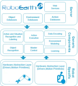
4.4.3 RoboEarth in a nutshell
The RoboEarth architecture is a collaboration of clients, RoboEarth Cloud Engine, RoboEarth Database which altogether make us of the ROS and Rapyuta. The clients are the Hardware Abstraction Layer that has Generic Software Components, which are shared in the cloud and then to the database. RoboEarth is composed by three-layers, as shown in Figure 9. The server layer is used to hold the RoboEarth database, where there are stored several standard models, including data on articles, situations, and activities connected to semantic data, and gives access to essential web services. The database and database services are open by means of regular web interfaces. The RoboEarth Consortium [43] is additionally implementing a hardware-independent middle layer as
shown in Figure 9, that provides different functionalities and communicates with robot-specific skills. The second layer implements the generic components, which are a part of the robot's local control software. Their main purpose is to enable the robot the interpretation of the map of the RoboEarth's robot behavior. The third layer is used for creating a generic interface for the robot's specific, hardware-dependent functionalities. Extra components are also available for the upgrade and expansion of the robot's detecting, reasoning, modelling, and learning abilities, depending on the customer requirements.
Figure 9: A simple robot control system.
4.4.4 The Rosbridge layer
Rosbridge [37] was developed as a middleware abstraction layer that offers robotics technology with a standard, minimalist application development framework that can be accessed by application programmers who are not expert in this area themselves. Rosbridge offers a simple, socket-based programmatic access to robot interfaces and algorithms provided by ROS through the use of Web technologies like JavaScript. Osentoski [44] proposed an infrastructure to enable Web services for robotics based on a lightweight JavaScript binding for ROS, called Ros.js. Ros.js exposes many capabilities of ROS, which enables application developers to develop controllers that are executed via a web browser. Users can develop their application through Robot Web tools, a collection of open source modules and tools for building web-based robot apps. Robot Web tools, as shown in Figure 10, combined rosbridge, Ros.js and open source libraries in JavaScript which facilitate the communication between the browser and the rosbridge. Robot Web tools, compared against standard ROS internal modules in terms of average bandwidth usage for transferring point cloud streams and other forms of compressed data, resulted more efficient in the compression of ROS messages, evaluated in terms of data size and compression time. Moreover, Sato et al. [8] proposed the Ubiquitous Network Robot Platform (UNR-PF), which realizes the design and development of robotic services that interact with people at different phases of their daily activities in various environments with the help of networked robot systems including robots, sensor networks and smartphones. The UNR-PF provides an API which can be easily connected with the components of Rosbridge.
Figure 10: Rosbridge's system architecture [32]
4.5.
McCormick Research
During the research of McCormick, Operating System for Cyber- Physical Manufacturing [6], researchers are developing an operating system and manufacturing network that would find its use in large-scale distributed networks. For making possible the creation of a system with features like data visualization and managment, the paper describes that the authors focused on developing a Digital Twin (DT), which is the same concept as the cyber-twin described earlier in this paper. During the research, the system engineers developed a distributed infrastructure that consisted of a big data application module, which allowed users to recreate their own application through a visual editor. In short, the applications were directed graphs that used data mining and machine learning algorithms as well as programming logics, with edges as data streams. This application logic allows users to connect their programming nodes and build functional applications adaptable to customer requirements without needing to go into the core of the application and botch with the internal structure of the algorithms. As we can see in Figure 11, where a three-cell manufacturing system shares data via cloud controlled by the digital system management demonstrated in Figure 12, the system architecture proposed by the McCormick research is slightly ahead of PADME's architectural style since the three-cell manufacturing system is already conceived as connected via cloud. Not only data is connected via the cloud, but in the core of the architecture, we can find the NOAM (Network Operational Administration and Management) system, which by being connected to every layer of the system, allows the administration of every component inside them. The system developed during McCormick's research was divided into four layers, network layer, operating system, virtualization layer and hardware layer , as shown in Figure 13. The hardware layer is composed by the cells that provide the data coming from the connected sensors, while the virtualization layer is an extra abstraction layer between operating, network and storage hardware, computing, and the application. In the core of the operating system, we can find the main database and the network layers, composed by CyMaN, a distributed network view, which on its own consists of NOAM and the Open Service Catalog Manager (OSCM) Broker connected with each other.
The OSCM Broker is an open source multi-platform service that enables end users to obtain and launch cloud resources and applications in self-service mode and manage cloud applications for service providers, IT Departments and End Users [7]. OSCM gives the opportunity to McCormick's proposed architecture to be always up-to-date and implement all emerging APIs adapted from the Service Broker Work Group. Furthermore, OSCM allows the integration of the data pulled from robots with cloud computing services widely used in the industry of nowadays, such as Microsoft Azure, Amazon Web Services, used for building, testing, and managing applications and services on the cloud. Based on the elements that compound the McCormick architecture, not only we can say that PADME's architecture is adaptable to it, but McCormick's research has already included inside its proposed structure a functional node to be connected with cloud services in the future.
Figure 11: A three-cell manufacturing system with shared resources on the network [6]
Figure 13: McCormick's proposed architecture [6]
4.6.
Temboo's Architecture
Temboo was created as a start-up company and launched a system architecture that improves the functionality of a simple PLC by turning it into a smart device while connecting it with robot controllers and data storage and management services. [8]. Temboo has created a PLC IoT Application that works for several types of industries apart from discreet manufacturing, the Temboo's PLC Sensor Alerts and Data Visualization App.
On each physical model of the architecture, there must be an embedded computer to enable autonomous decisions and retrieve required information via cloud computing and CPS. In the architecture, the use of Siemens SIMATIC S7120 basic controllers affects the range of functions and integrated IOs as well as their particularly compact space-efficient design. The Siemens SIMATIC S71200 PLC offers an overview of data going through the PLC, alerts when sensors read certain thresholds, and charts and graphs to interpret and understand the information, as shown in Figure 14 in an example about the levels of a water tank. From the hardware perspective, there needs to be a gateway, which is the internet connected device that serves as the main connection point between the data from the PLC and the cloud, and vice versa. Temboo has three Machine to Machine (M2M) communication protocols for Arduino boards: MQTT, CoAP, and HTTP, as shown in Figure 15.
When using Temboo, users have the possibility to choose which of the three protocols to use. Temboo, through M2M, enables the possibility to program flexible distributed device applications in minutes. Networked sensors and devices enable multiple sorts of IoT applications to be connected with robot controllers.
After analyzing all the structure of the architecture, we see that the Temboo's architecture and PADME's one have multiple similarities, with the only difference being the communication protocol and Temboo's alleged flexibility in getting integrated with several systems other than
Figure 14: Temboo visualization application showing the level of water. [8]
discreet manufacturing processes. We suppose that Temboo would be possible to implement if it adapted the communication protocols of PADME but kept its Data Visualization App and Sensor Alert service. In addition, one advantage of Temboo is that the connection between the PLC and the cloud services happen by using a cloud storage gateway, a connection point between the sensors of the PLC and the cloud [8]. The gateway works as well with development boards like Arduino or Raspberry Pi, which would be the first choice when opting for low-cost solutions and IoT applications.
Figure 15: Temboo's simplified architecture. [8]
4.7.
KUKA
KUKA has developed many devices in the field of robotics and engineering [35], which are known to co-operate with each other in intelligent ways. KUKA has had the same approach as PADME and has already implemented a system architecture for discreet manufacturing processes. The main applications KUKA has developed are the KUKA Connect and KUKA Control Panel. KUKA Connect serves the middle-man intelligent device, while the Control Panel as a Human-Machine interface hub to the robot controller and other components. Since KUKA Connect is cloud-based, new features can be added without any KUKA Connect software installation required on a work-station, but instead they can be downloaded through the marketplace created specifically for this reason, called KUKA Marketplace. Meanwhile, the components of the architecture, compared to our case architecture, make use of the Transport Layer Security (TLS), cryptographic protocol sug-gested by the NIST for secure communication [35], which means that the company does not make use of the OPC UA protocol. Bischoff [35] mentions that KUKA uses a modular hardware
struc-ture and open, PC-based software architecstruc-ture, which allows users to easily adapt the controller to the specific requirements of other systems, but also to get access to a wide range of expansion options. KUKA offers users as well an upgradable system software, ready-made robot applications and software-based controllers for the 3D visualization and simulation [35]. This makes possible offering constant support via a user-friendly interface for the robot's hardware and software, by making sure interactions between humans and machines are safe [35].
Figure 16: KUKA's System Architecture
In Figure 16, we have represented the architectural style that KUKA components are connected with, based on the descriptions found in [35]. The architecture's main components are the HMI, application-specific code, the KUKA Panel Control and KUKA Robot Controller. It is noticeable how the workflow of the architecture is differently executed compared to PADME. The robot controller, through an I/O device and the TLS communication protocol, sends information through the internet protocol TCP/IP to the user interface found in KUKA Control Panel. In Figure 17., we can notice instead of the differences with PADME's solution in the processes that the data from the robot controller has to go through. The data is pulled from the user input in the HMI and then get processed, features are extracted and then the components KUKA Independent Function, KUKA Dependent Function, translate the input into application code for the robot to start operating. The HMI allows the user to access the data stored through an Ethernet interface, where it can be later re-used from the data-acquisition system for advanced analysis and test logging purposes.
Figure 17: KUKA's Robot Communication
4.8.
Hirebotics - Universal Robots
Hirebotics is a recently founded company which acts as a certified integrator and developer of the robots built from Universal Robots. Due to the company's recent creation, very little information could be found about the system architecture of components. Hirebotics uses TCP/IP for the connection of the robot arm with the cloud infrastructure, built from the company itself to support its services [45]. Since the company is supplied with the robot arms from Universal Robots, they do not include in the architecture a separate PLC, the functions of which are included in the robot itself with an expansion of it with Modbus TCP for expansion I/O [45]. Through TCP/IP sockets or XML remote procedure calls, clients can choose any stable framework from libraries able to have multiple functionalities for the robot and integrated it with API layers of the clients choice. The system is equipped as well with a user-friendly interface, integrated with the system and accessible with a mobile phone, or tablet. The Figure 18.shows a simplified version of how Hirebotics system architecture is compound.
![Figure 1: The system architecture of robots operating via cloud from Wan et al [1]](https://thumb-eu.123doks.com/thumbv2/5dokorg/4562594.116491/9.892.242.653.128.438/figure-architecture-robots-operating-cloud-wan-et-al.webp)
![Figure 3: An IoT system has a three-level architecture; devices, gateways and the data system [2]](https://thumb-eu.123doks.com/thumbv2/5dokorg/4562594.116491/10.892.192.683.709.1033/figure-iot-level-architecture-devices-gateways-data.webp)

![Figure 4: Information modeling of the OPC UA [3]](https://thumb-eu.123doks.com/thumbv2/5dokorg/4562594.116491/13.892.155.732.426.621/figure-information-modeling-of-the-opc-ua.webp)
![Figure 6: The Domain Architecture Comparison Framework (DACF) [4]](https://thumb-eu.123doks.com/thumbv2/5dokorg/4562594.116491/18.892.184.713.273.474/figure-domain-architecture-comparison-framework-dacf.webp)
![Figure 8: DAvinCI 's Web Engineering Framework [5]](https://thumb-eu.123doks.com/thumbv2/5dokorg/4562594.116491/22.892.280.614.761.957/figure-davinci-s-web-engineering-framework.webp)
![Figure 10: Rosbridge 's system architecture [32]](https://thumb-eu.123doks.com/thumbv2/5dokorg/4562594.116491/26.892.189.707.126.398/figure-rosbridge-s-system-architecture.webp)
![Figure 11: A three-cell manufacturing system with shared resources on the network [6]](https://thumb-eu.123doks.com/thumbv2/5dokorg/4562594.116491/27.892.201.689.162.379/figure-cell-manufacturing-shared-resources-network.webp)
