http://www.diva-portal.org
This is the published version of a paper presented at 4th International Symposium on Future
Active Safety Technology towards Zero-Traffic-Accidents (FAST-Zero’17), Nara, Japan,
18-22 September, 2017.
Citation for the original published paper:
Aramrattana, M., Englund, C., Jansson, J., Larsson, T., Nåbo, A. (2017)
Safety Analysis of Cooperative Adaptive Cruise Control in Vehicle Cut-in Situations.
In: Proceedings of 2017 4th International Symposium on Future Active Safety
Technology towards Zero-Traffic-Accidents (FAST-zero), 20174621 Society of
Automotive Engineers of Japan
N.B. When citing this work, cite the original published paper.
Permanent link to this version:
Safety Analysis of Cooperative Adaptive Cruise Control in Vehicle Cut-in
Situations
Maytheewat Aramrattana
1,3), Cristofer Englund
1,2), Jonas Jansson
3), Tony Larsson
1), and Arne Nåbo
3)1) The School of Information Technology, Halmstad University
PO Box 823, SE-301 18, Halmstad, Sweden (E-mail: maytheewat.aramrattana@hh.se) 2) RISE Viktoria
Lindholmspiren 3A, SE-417 56 Göteborg, Sweden
3) The Swedish National Road and Transport Research Institute (VTI), VTI, SE-581 95 Linköping, Sweden
ABSTRACT: Cooperative adaptive cruise control (CACC) is a cooperative intelligent transport systems (C-ITS) function,
which especially when used in platooning applications, possess many expected benefits including efficient road space utilization and reduced fuel consumption. Cut-in manoeuvres in platoons can potentially reduce those benefits, and are not desired from a safety point of view. Unfortunately, in realistic traffic scenarios, cut-in manoeuvres can be expected, especially from non-connected vehicles. In this paper two different controllers for platooning are explored, aiming at maintaining the safety of the platoon while a vehicle is cutting in from the adjacent lane. A realistic scenario, where a human driver performs the cut-in manoeuvre is used to demonstrate the effectiveness of the controllers. Safety analysis of CACC controllers using time to collision (TTC) under such situation is presented. The analysis using TTC indicate that, although potential risks are always high in CACC applications such as platooning due to the small inter-vehicular distances, dangerous TTC (TTC < 6 seconds) is not frequent. Future research directions are also discussed along with the results.
KEY WORDS: cooperative adaptive cruise control, modelling and simulation
1. Introduction
Nowadays, there is extensive research on connected and automated vehicles. Higher levels of automation are being added to vehicles, as well as the capability for vehicles to be connected via wireless communication, which often is referred to as vehicle-to-vehicle (V2V) and vehicle-to-infrastructure (V2I) communication. By using wireless communication technologies, automated vehicles interact with each other and parts of the road infrastructure, forming cooperative intelligent transport systems (C-ITS). Expected benefits from such systems are massive in terms of improved energy efficiency, safety, and sustainability of the transport systems. As soon as 2019, European Commission is planning to deploy sets of Day 1, and Day 1.5 C-ITS services (1).
Apart from Europe, projects aiming towards C-ITS deployment can be seen around the world, e.g. the Connected Vehicle Pilot Deployment Program in USA(2), and other projects in Korea,
Australia, etc.
Cooperative adaptive cruise control (CACC) is one example of a C-ITS function, which has the potential to be deployed in the near future. One application of CACC is platooning, where vehicles automatically follow each other with small inter-vehicular distance. A string of such vehicles is often referred to as a “platoon”. The goals of platooning are, for example, to make more efficient use of the road space by reducing the inter-vehicular distance, and to reduce fuel consumption by the reduced aerodynamic drag obtained by the short distance between the vehicles. In theory, several control strategies for CACC have been proposed. CACC controllers are mainly designed to enable small-inter vehicular distance, while maintaining string stability (a platoon is string stable when the effects from control errors, or disturbances, do not
amplify backwards to the followers in the platoon). Details regarding definitions and operation concepts of CACC is described in (3). Furthermore, a few highway platooning scenarios have been
demonstrated such as in the Grand Cooperative Driving Challenge
(4)(5), and the European Truck Platooning Challenge (6).
In most CACC-related literature, a homogeneous platoon is often assumed, i.e. all vehicles in the platoon are identical, connected, and automated. However, during the early deployment phase of C-ITS, there will be a mixture of vehicles with different automation and connectivity capabilities driving in the same traffic environment. Furthermore, in real traffic scenarios, cut-in manoeuvres can be frequently expected, both from connected and non-connected vehicles. Cut-in manoeuvres can potentially reduce the benefits of platooning, and are thus not desired from a safety perspective. In spite of that, cut-in scenarios are not often considered in research related to CACC or platooning. To the authors’ knowledge, only a few publications in the area have considered cut-in manoeuvres in their studies. For instance, the work from Milanés and Sladover (7) proposed an approach to
handle the cut-in by switching the controller to adaptive cruise control (ACC) when the cut-in is detected. On road experiments as well as simulation results are presented in their paper, analysing effects of the cut-in on string stability. From human driver’s perspective, Larsson et al. (8) studied response time of the human
driver under a cut-in situation. Even though the study was with ACC-equipped vehicle, learning how the human drivers would react to the cut-in is of interest.
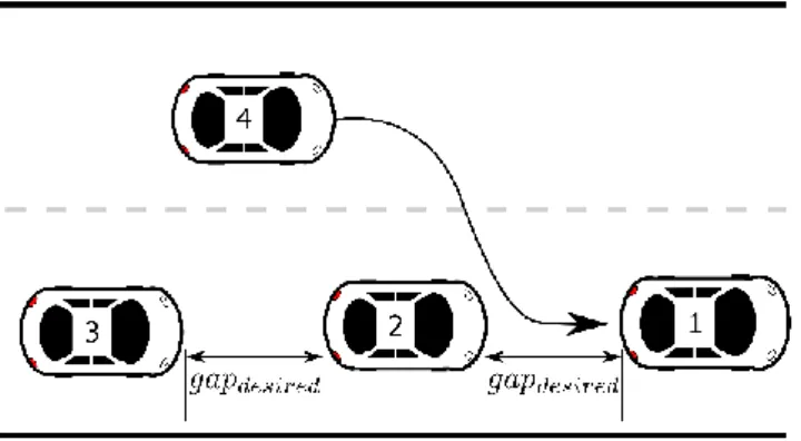
Therefore, this paper presents safety analysis of two different CACC controllers in a simulated cut-in scenario on a highway. During the scenario, depicted in Fig. 1, a non-connected vehicle performs a cut-in manoeuvre into the gap between the first, and the
Copyright 2017 Society of Automotive Engineers of Japan, Inc. All rights reserved second vehicle of the platoon. The non-connected vehicle is driven
by a human driver using the driving simulation software from the Swedish National Road and Transport Research Institute (VTI). Data from seven participants are collected from the simulations.
Fig. 1 A vehicle cut-in scenario, where vehicle number 4 is cutting in between vehicle 1 and 2.
The rest of the paper is organized as follows. Section 2 describes the simulation framework used in this study, along with details about the two CACC controllers. Set up of the simulation study is explained in Section 3. The results are presented in Section 4. Section 5 presents the safety analysis with the discussions in Section 6. Finally, Section 7 concludes the paper.
2. Background
The C-ITS simulation framework used in this paper has been developed previously (9)(10). The framework is a combination of
driving-, traffic-, and network simulators. As mentioned above, the driving simulation software is developed by VTI. It is a driving simulation software, which can be run either on a desktop computer, or a complete moving-base driving simulator (11). For the traffic and
network simulators, The Platooning Extensions for Veins (Plexe)
(12) is used. Plexe is a traffic and network simulation framework,
based on the traffic simulator, Simulation of Urban Mobility (SUMO), and the network simulator, Vehicle in Network Simulation (Veins). Plexe extends SUMO and Veins with support for studying platooning applications. An overview of the C-ITS simulation framework and existing models are illustrated in Fig. 2.
Fig. 2 Overview of the C-ITS simulation framework.
In the C-ITS simulation framework, the human driver can either drive manually or visualize the automated vehicle from the driver perspectives. Moreover, the human driver can interact with the other vehicle in the simulation, e.g. pushing a button on the steering wheel to send V2V communication messages. The rest of the vehicles are automatically controlled by car-following models in SUMO. For simulation of platooning scenarios, Plexe added a number of car-following models to SUMO, including the implementation of two existing CACC controllers.
The first controller defined in Chapter 7 of (13), will be referred
to as the Rajamani controller in this paper. The second CACC controller was proposed in (14), and will be referred to as Ploeg
controller in this paper. The two controllers have different control strategies, and rely on different information sources, as summarized in Table 1. The Rajamanicontroller uses a “constant distance gap” strategy, which means that the controller is designed to maintain a desired inter-vehicular distance to the vehicle in front. On the other hand, the Ploeg controller uses a “constant time headway” strategy. The time headway is defined as the time gap between when the rear bumper of the preceding vehicle, and the front bumper of the ego vehicle, reach the same fixed point on the road. In this case, the actual inter-vehicular distance depends on the speed of the ego vehicle. Moreover, as listed in Table 1, the Rajamani controller relies more on information exchanged via V2V communication, while the Ploegcontroller, to a larger extent, trust on information from the radar.
All vehicles are assumed to be equipped with a forward-looking radar, which will detect an object that is in front of it in the same lane. Lane changing in SUMO is discrete, i.e. vehicles instantaneously switch from one lane to another. Such lane changing decisions are determined by the position of the front axle of the ego vehicle in the driving simulation. In other words, as soon as the front axle of the ego vehicle crosses the lane marking, the corresponding vehicle in SUMO is switched to another lane. Furthermore, the platooning vehicles (vehicle no. 1,2, and 3) are assumed to be equipped with V2V communication modules according to the IEEE 802.11p standard.
Table 1 Control parameters of the two existing CACC controllers in Plexe.
Controller Control parameters Rajamani Ploeg Control strategy distance time headway Platoon leader’s speed V2V - Platoon leader’s acceleration V2V - Preceding vehicle’s speed V2V Radar Preceding vehicle’s acceleration V2V V2V Distance to preceding vehicle Radar Radar
3. Simulation Setup
Seven participants have participated in the study. Upon arrival, each participant was given time to familiarize with controlling the vehicle in the driving simulation software. Then, the scenario is explained to the participant.
According to Fig. 1, the participant is driving the vehicle no. 4, and is asked to perform a cut-in between vehicle no. 1 and 2. Vehicle no. 1, 2, and 3 are connected and automated vehicles driving with CACC functionality. The leader of the platoon
(vehicle no.1) drives at a constant speed of 90 km/h. Two existing CACC controllers in Plexe were used with two different desired inter-vehicular distances of 30 meters (1.2 seconds headway at 90 km/h) and 17.5 meters (0.7 seconds headway at 90 km/h).
Fig. 3 The setup for driving simulation.
Two desktop computers were used to run the simulation framework, one for the Plexe framework, and the other for the driving simulation software. The driving simulation setup for the participants is depicted in Fig. 3. The simulation is run for 100 seconds, and data is collected both from the Plexe framework and from the driving simulator. At each simulation run, the same CACC controller and desired distance is chosen for all vehicles in the platoon. Each participant has driven each scenario at least once.
4. Cut-in Manoeuvres
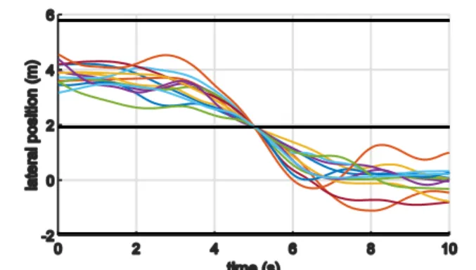
Fig. 4 and Fig. 5 illustrate all cut-in manoeuvres recorded by the driving simulation software, and the average cut-in manoeuvres from the recorded data, respectively. The plots show five seconds before and after each cut-in occurs. The horizontal black lines, which is drawn at the lateral position approximately -2, 2, and 6 meters, represents the position of the lane marking.
Fig. 4 Traces from all participants during lane change.
Fig. 5 Average of the traces from all participants during lane change.
Furthermore, the results show that the inter-vehicular distance of the platoon seems to have effects on the human cut-in behaviour. All cut-in manoeuvres are then divided into two groups based on the scenario, i.e. when the desired inter-vehicular distance of the platoon 30 meters, and 17.5 meters. All cut-in manoeuvres when the platoon’s inter-vehicular distance is 30 meters, and 17.5 meters are depicted in Fig. 6, and Fig. 8, respectively. The average of the cut-in manoeuvres for the 30 meters distance, and 17.5 meters distance, are illustrate in Fig. 7, and Fig. 9, respectively. According to the figures, a few participants tend to be closer to the lane marking before performing the cut-in when the inter-vehicular gap is 17.5 meters.
Table 2 Summary of the distances measured from vehicle no.2 to the vehicle no.4 when the cut-in occurs.
CACC gap Cut-in distance (m) 30m (n = 13) 17.5m (n = 13) Maximum 18.96 9.86 Minimum 2.73 2.26 Mean 10.87 5.99 SD 5.10 2.45
Table 3 Summary of the distances measured from the ego vehicle (no.4) to the vehicle no.1 when the cut-in occurs.
CACC gap Cut-in distance (m) 30m (n = 13) 17.5m (n = 13) Maximum 23.28 11.24 Minimum 7.04 3.64 Mean 15.53 7.59 SD 4.85 2.49
Copyright 2017 Society of Automotive Engineers of Japan, Inc. All rights reserved Fig. 6 Traces of vehicles performing cut-in manoeuvres when the
platoon’s desired inter-vehicular distance is 30 meters.
Results in Table 2 and Table 3 suggest that, on average, the drivers leave more gap in front than behind the ego vehicle while performing a cut-in manoeuvre.
5. Safety Analysis
In traffic systems, time to collision (TTC) is often used as a safety indicator (15). The following definition of TTC will be used
in this paper.
TTC =𝑋𝑖−1(𝑡)− 𝑋𝑖(𝑡)−𝑙𝑖
𝑋̇𝑖(𝑡)−𝑋̇𝑖−1(𝑡) ∀ 𝑋̇𝑖 (𝑡) > 𝑋̇𝑖−1(𝑡) (1)
Where 𝑋𝑖 is the position of vehicle 𝑖, 𝑋̇𝑖 is the speed of vehicle 𝑖,
and 𝑙𝑖 is the length of vehicle 𝑖. The ego vehicle is indicated with
the index 𝑖, and the preceding vehicle is indicated with the index 𝑖 − 1. In this case, vehicle no. 2 is the vehicle 𝑖 and vehicle no. 4 is the vehicle 𝑖 − 1. The length of all vehicles is 4 meters.
Fig. 7 Average trace of vehicles performing cut-in manoeuvres when the platoon’s desired inter-vehicular distance is 30 meters.
Fig. 8 Traces of vehicles performing cut-in manoeuvres when the platoon’s desired inter-vehicular distance is 17.5 meters.
Fig. 9 Average trace of vehicles performing cut-in manoeuvres when the platoon’s desired inter-vehicular distance is 17.5
meters..
According to (15), a TTC more than 6 seconds can be considered
as safe. In other words, TTC more than 6 seconds is enough to ensure that the follower will not be forced to perform any dangerous avoidance manoeuvres, even with a standstill obstacle (unless the vehicle is driving faster than 130 km/h). Among all collected datasets there are 2 cases, where the TTC is less than 6 seconds, one for each controller when the desired inter-vehicular distance is set to 17.5 meters. Moreover, in these two situation, the TTC is less than 3 seconds, which is enough to trigger the emergency braking system, according to (16) (“The emergency
braking phase shall not start before TTC is equal to, or less than, 3.0 seconds”). The following subsections describe the scenarios with the two different controllers.
5.1 The Rajamani Controller
The inter-vehicular distance measured from vehicle number 2 when the cut-in occurs is 2.37 meters, and the distance is 11.19 meters measured from the ego vehicle (vehicle number 4). The measured distances, and speed are presented in Fig. 11, and Fig. 12, respectively. Fig. 10 shows the TCC after the cut-in occurs at 44.9 seconds.
Fig. 10 The TTC when the vehicle no. 2 is operated by the Rajamani controller.
Fig. 11 Plots of the distances measured from vehicle no. 2, 3, and 4 during the cut-in. Vehicle 2 and 3 are operated by the
Rajamani controller.
Fig. 12 Speed of vehicle no. 2, 3, and 4 during the cut-in. Vehicle no. 2 and 3 are operated by the Rajamani controller. 5.2 The Ploeg Controller
In this case, the inter-vehicular distance measured from vehicle number 2 when the cut-in occurs is 2.26 meters.
Fig. 13 The TTC when the vehicle no. 2 is operated by the Ploeg controller.
The distance measured from the ego vehicle is 11.24 meters. The measured distance, and speed during the scenario are presented in Fig. 14, and Fig. 15, respectively. Fig. 13 shows the TCC after the cut-in occurs at 40.8 seconds. This short TTC period is longer than that of the Rajamani controller.
Fig. 14 Plots of the distances measured from vehicle no. 2, 3, and 4 during the cut-in. Vehicle no. 2 and 3 are operated by the
Ploeg controller.
Fig. 15 Speed of the vehicle no. 2, 3, and 4 during the cut-in. Vehicle no. 2 and 3 are operated by the Ploeg controller.
6. Discussion
Although not considered in this study, an emergency braking system can be triggered at a TTC less than 3 seconds, as mentioned above. With sufficient V2V communication coverage, a coordinated emergency braking manoeuvre can be used to ensure safety within the platoon. However, such emergency braking may compromise safety of other road users, which are not aware of the emergency braking manoeuvre.
As pointed out in (15), TTC and time headway are different. A
short time headway indicates potential danger; while a small TTC represents actual danger. In an application like platooning, where vehicles are driving with small inter-vehicular distance, time headway is almost always small. The 30 meters inter-vehicular distance, corresponds to the time headway of 1.2 seconds, can be considered as small. This is comparable to the time headway of adaptive cruise control (ACC) functions that are available nowadays. Furthermore, 0.7 seconds time headway, which corresponds to 17.5 meters inter-vehicular distance, indicates more potential danger. Such short time headway can sometimes lead to small TTC, as presented in the results in Section 5, for instance.
The two controllers used as examples are certainly not designed to handle cut-in manoeuvres as their main goal. Furthermore, one can observe different behaviours among the two controllers in Fig. 11, and Fig. 14. The Ploeg controller reacts faster to maintain the desired inter-vehicular distance, while on the other hand, the Rajamani controller seems to take longer time to recover after the
Copyright 2017 Society of Automotive Engineers of Japan, Inc. All rights reserved cut-in. However, such behaviours are heavily influenced by the
speed variation of the human driver after the cut-in, which is not the same in this case. Thus, to carefully analyse the controllers’ behaviour, a more repeatable cut-in manoeuvre is required. For instance, by replaying the same logged data to different controllers.
Nevertheless, both controllers perform well to handle the situations and prevent a collision, given that the controllers are not aware that the cut-in occurs. One solution to handle the cut-in is to switch to ACC, when the cut-in is detected, as suggested in (7),
which is reasonable given that there is no way to anticipate or detect the cut-in manoeuvre before it occurs.
In this study, regardless of the cut-in manoeuvre, the controllers have the same perception, i.e. the sudden change detected in the radar measurements when a cut-in occurs. If the platoon can be aware of the cut-in. For example, if vehicle no. 4 has connectivity, but no automation capabilities. Scenarios where a request message is sent before the cut-in, similar to the usage of turning indicators, can be simulated. Consequently, as future work, benefits of having such information beforehand can be studied. Also, different algorithms to handle the request message and react to it in a safe and efficient manner can be developed.
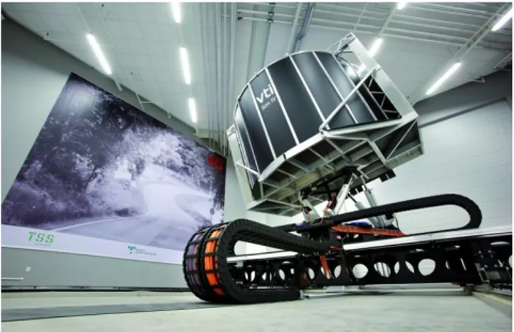
The driving simulation setup in this study is arguably simple, because the main test subject is the CACC controllers, and the human driver is acting as disturbance to the platoon. As future work, running the same study on a moving-base driving simulator such as Sim IV (see Fig. 16), research questions related to human factors can be studied. For instance, how big inter-vehicular gap is acceptable to the human driver? Moreover, cut-in manoeuvres can be collected, and used to create a realistic car-following model with cut-in manoeuvre for testing CACC controllers.
Fig. 16 The Sim IV, moving-base driving simulator located at the VTI site in Gothenburg, Sweden.
At the beginning of the simulation, the manually driven vehicle starts at zero speed, while the platoon starts at 100 km/h, thus the participants need to accelerate and catch up with the platoon. Therefore, large time variation can be observed in Table 4, because each participant has their own approach to control the vehicle. In all cases, the participants took approximately 42-43 seconds on average, until he or she performs the first cut-in manoeuvres in between the vehicle no. 1 and no. 2, as presented in the Table 4.
Table 4 Summary of the time taken before the participants perform the first cut-in manoeuvres.
CACC gap Cut-in time (s) all 30m 17.5m Maximum 73.54 71.29 73.54 Minimum 29.26 29.26 30.39 Mean 42.41 43.59 42.44 SD 10.78 11.52 11.05 7. Conclusions
This study explores behaviour of two different CACC controllers under a cut-in scenario by a non-connected vehicle. The non-connected vehicle is driven by human driver via a desktop driving simulator. Results from seven participants are presented in the paper.
Safety analysis of the two CACC controllers using TTC is discussed. Although, potential risks are always high in CACC applications due to the small inter-vehicular distance, dangerous TTC (TTC < 6 seconds) is not commonly observed. This is perhaps because of the CACC controllers’ speed regulation; or TTC is not the best measure to analyse safety of CACC operations. However, under this specific scenario, the TTC results indicate that the two controllers can handle the situation fairly well, even though they are not designed specifically to do so.
Several future research directions are discussed in Section 6. However, the authors’ main interest is to find a methodology for determining safe operation of CACC controller in mixed traffic scenarios. Thus, this study can be regarded as a pilot study towards a safety analysis framework for evaluating safety of the operations of CACC controllers in mixed traffic scenarios. In the future work, the scenario will be extended to include, e.g. speed variation of the platoon leader, V2V communication capability on the cut-in vehicle, realistic driving simulator setup, etc.
References
(1) European Commission, “COM/2016/0766, A European strategy on Cooperative Intelligent Transport Systems, a milestone towards cooperative, connected and automated mobility,” 2016.
(2)“Connected Vehicle Pilot Deployment Program (https://www.its.dot.gov/pilots/).”
(3) S. E. Shladover, C. Nowakowski, X.-Y. Lu, and R. Ferlis, “Cooperative Adaptive Cruise Control: Definitions and Operating Concepts,” Transp. Res. Rec. J. Transp. Res. Board, no. 2489, pp. 145–152, 2015.
(4) J. Ploeg, S. Shladover, H. Nijmeijer, and N. van de Wouw, “Introduction to the special issue on the 2011 grand cooperative driving challenge,” Intell. Transp. Syst. IEEE Trans., vol. 13, no. 3, pp. 989–993, 2012.
(5) C. Englund et al., “The Grand Cooperative Driving Challenge (GCDC) 2016 - boosting the introduction of Cooperative Automated Vehicles,” IEEE Wirel. Commun. Mag., no. August 2016 Issue, 2016.
(6)“European Truck Platooning Challenge (https://www.eutruckplatooning.com).”
(7) V. Milanés and S. E. Shladover, “Handling Cut-In Vehicles in Strings of Cooperative Adaptive Cruise Control
Vehicles,” J. Intell. Transp. Syst., vol. 20, no. 2, pp. 178– 191, 2016.
(8) A. F. L. Larsson, K. Kircher, and J. A. Hultgren, “Learning from experience: Familiarity with ACC and responding to a cut-in situation in automated driving,” Transp. Res. Part F Traffic Psychol. Behav., vol. 27, Part B, pp. 229–237, 2014. (9) M. Aramrattana, T. Larsson, J. Jansson, and A. Nåbo,
“Extended Driving Simulator for Evaluation of Cooperative Intelligent Transport Systems,” in Proceedings of the 2016 Annual ACM Conference on SIGSIM Principles of Advanced Discrete Simulation, 2016, pp. 255–258. (10) M. Aramrattana, T. Larsson, J. Jansson, and A. Nåbo,
“Cooperative Driving Simulation,” in The Driving Simulation Conference 2016 VR, 2016.
(11) J. Jansson, J. Sandin, B. Augusto, M. Fischer, B. Blissing, and L. Källgren, “Design and performance of the VTI Sim IV,” in Driving Simulation Conference, 2014.
(12) M. Segata, S. Joerer, B. Bloessl, C. Sommer, F. Dressler, and R. L. Cigno, “Plexe: A platooning extension for Veins,” in 2014 IEEE Vehicular Networking Conference (VNC), 2014, pp. 53–60.
(13) R. Rajamani, Vehicle dynamics and control, 2nd ed. Springer US, 2012.
(14) J. Ploeg, B. T. M. Scheepers, E. van Nunen, N. van de Wouw, and H. Nijmeijer, “Design and experimental evaluation of cooperative adaptive cruise control,” in 2011 14th International IEEE Conference on Intelligent Transportation Systems (ITSC), 2011, pp. 260–265. (15) K. Vogel, “A comparison of headway and time to
collision as safety indicators,” Accid. Anal. Prev., vol. 35, no. 3, pp. 427–433, 2003.
(16) European Commission, “COMMISSION REGULATION (EU) No 347/2012 of 16 April 2012 implementing
Regulation (EC) No 661/2009 of the European Parliament and of the Council with respect to type-approval
requirements for certain categories of motor vehicles with regard to advanced emer.” 2012.