MEE05:30
Optimization of Audio Processing
algorithms (Reverb) on ARMv6
family of processors
Farzad Foroughi Abari
This thesis is presented as part of Degree of Master of Science in Electrical Engineering
Blekinge Institute of Technology
October 2007
Blekinge Institute of Technology School of Engineering
Department of Applied Signal Processing Academic Supervisor: Dr. Nedelko Grbic Industrial Supervisor: Dr. Peter Eneroth Academic Examiner: Dr. Nedelko Grbic Industrial Examiner: Dr. Peter Eneroth
Abstract
Audio processing algorithms are increasingly used in cell phones and today’s customers are placing more demands on cell phones. Feature phones, once the advent of mobile phone technology, nowadays do more than just providing the user with MP3 play back or advanced audio effects. These features have become an integral part of medium as well as low-end phones. On the other hand, there is also an endeavor to include as improved quality as possible into products to compete in market and satisfy users’ needs.
Tackling the above requirements has been partly satisfied by the advance in hardware design and manufacturing technology. However, as new hardware emerges into market the need for competence to write efficient software and exploit the new features thoroughly and effectively arises. Even though compilers are also keeping up with the new tide space for hand optimized code still exist.
Wrapped in the above goal, an effort was made in this thesis to partly cover the competence requirement at Multimedia Section (part of Ericsson Mobile Platforms) to develope optimized code for new processors. Forging persistently ahead with new products, EMP has always incorporated the latest technology into its products among which ARMv6 family of processors has the main central processing role in a number of upcoming products.
To fully exploit latest features provided by ARMv6, it was required to probe its new instruction set among which new media processing instructions are of outmost importance. In order to execute DSP-intensive algorithms (e.g. Audio Processing algorithms) efficiently, the implementation should be done in low-level code applying available instruction set. Meanwhile, ARMv6 comes with a number of new features in comparison with its predecessors. SIMD (Single Instruction Multiple Data) and VFP (Vector Floating Point) are the most prominent media processing improvements in ARMv6.
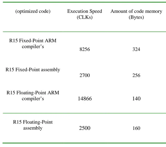
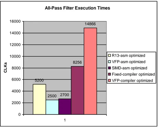
Aligned with thesis goals and guidelines, Reverb algorithm which is among one of the most complicated audio features on a hand-held devices was probed. Consequently, its kernel parts were identified and implementation was done both in fixed-point and floating-point using the available resources on hardware. Besides execution time and amount of code memory for each part were measured and provided in tables and charts for comparison purposes. Conclusions were finally drawn based on developed code’s efficiency over ARM compiler’s as well as existing code already developed and tailored to ARMv5 processors. The main criteria for optimization was the execution time. Moreover, quantization effect due to limited precision fixed-point arithmetic was formulated and its effect on quality was elaborated.
The outcomes, clearly indicate that hand optimization of kernel parts are superior to Compiler optimized alternative both from the point of code memory as well as execution time. The results also confirmed the presumption that hand optimized code using new instruction set can improve efficiency by an average 25%-50% depending on the algorithm structure and its interaction with other parts of audio effect. Despite its many draw backs, fixed-point implementation remains yet to be the dominant implementation for majority of DSP algorithms on low-power devices.
Acknowledgments
I would like to express my sincere appreciation to all people who helped me with their constructive feedback during the thesis work specifically to Audio Effects team members who assisted me with their effortless support. I should specifically thank Dr. Peter Eneroth at EMP as well as Dr. Nedelko Grbic at BTH who supervised my project from industry and university sides. Also many thanks to Andreas Lundgren whose supportive presence and help hugely accelerated my progress. Patrik Sandgren from Ericsson Research also provided constructive feedback on the reverb structure. Thanks to many discussions that we had, the new Reverb implementation is a truly optimal solution. Nevertheless, special thanks go to Jan Ringius who as a line manager helped me with just any facility and administrative support at EMP. Had I not received his encouragement and support along the way I would have had harder time finalizing my thesis.
Introduction 9
- Motivation 9
- Objectives 10
- Outline 11
Chapter 1 13
- Introduction to audio processing algorithms 13
- Reverberation effect 14
- Reverberation algorithm in R13 16
- Reverberation algorithm in R15 17
Chapter 2 19
- Digital Signal Processors (DSP) 19
- General purpose processors versus DSPs 21
- ARM architecture concept 21
- ARMv6 family of processors 24
- ARM1176jzfs processor 30
Chapter 3 31
- DSP algorithm implementation and optimization 31
- Signal representation 33
- Reverberation implementation in R13 35
- Reverberation implementation in R15 38
- Comparison results and conclusions 49
Chapter 4 51
- Quantization noise in Fixed point arithmetic 51 - SNR in Reverberation algorithm implementation 54
Chapter 5 61
- Conclusions and future work 61
References 65
Introduction
Audio signal processing has always been a point of great interest in many applications as well as products. Their wide applications in entertainment industry have involved a large number of people applying this technology. Listening to music on the go has become a customary part of life in the 21st century. iPODs, MP3 players, cell-phones and many other various products enjoy audio processing algorithms to compete in quality and provide their end users with an ultimate solution. Meanwhile, gaming industry is expanding as fast. Virtual reality features enjoying 3D audio are becoming ordinary components of a gaming device. It is needless to mention that their evolution is hugely dependant on audio and accelerated video effects. Meanwhile, cell phones featuring advanced audio/video capabilities are emerging fast. They are already providing the user with multiple functionalities including advanced audio/video enabled features. It is expected that future cell phones will occupy a large portion of digital market in the foreseeable future. More powerful phones will enable the flexibility of using more complicated features among which audio effects are highly desirable. Advanced audio/video algorithms will be implemented on cell phones and cell phones are expected to replace MP3 players and iPODs of the future. However, this is not as simple job as it might sound. Mobile phones were initially designed for other different purposes namely voice conversation over wireless communication. Merging the new needs with the old requirements not only requires more complicated hardware but also more intelligent software. This is where the need for higher optimization arises. Cell phones are designed to enjoy the application of existing hardware. However, hardware requirements have always been constrained by the existing technology. As a result, many restrictions in hardware should be addressed with optimally developed software. Consequently, the main objective from software’s point of view is to run the applications on a hardware which occupies as low silicon area as possible while it has the lowest feasible power consumption. To simply state that in technical terms, a software is desired which needs the lowest amount of memory while it requires the minimum clock cycles for execution. This is why code optimization is persistently probed while it has always been in the center of attention.
Motivation
Many audio algorithms are already used in existing cell phones and cell phones are the primary product of future when every single human operator is expected to have one. They are expected to increase their share immensely in market. It is not far from reality if we think of future cell phones as means of providing the user with ample secondary functions which will cover the primary goal for its existence, wireless communication. To achieve such objectives, advanced algorithms should be implemented on high-tech hardware. Yet, restrictions in hardware have always hindered application of cutting-edge algorithms. This is precisely where software implementation’s role is signified. On one hand it is required to develop low-complexity algorithms and on the other hand it is required to have a highly efficient and optimized software implementation. Typically, optimized software not only satisfies the requirements of applications but also it should be tailored to the restrictions of hardware.
Aligned with the above mentioned facts, EMP has come up with numerous solutions to implement audio effects as part of a multimedia package. Highly optimized code is
continuously being developed to address the needs of customers. Hardware choices have also passed many revisions and updated software has replaced older one to be consistently run on the latest platforms. Prior to one of EMP’s latest platforms (R15) many solutions were harnessed and various hardware & software were utilized. However, due to many reasons which are partly elaborated in this thesis, ARMv6 processors are specifically utilized in R15 to address the signal processing requirements. As a result, it is highly desirable to have optimized codes for algorithms which are targeted at these latest processors. Among existing algorithms in audio effects, Reverberation has been of interest. Its numerous appearances in many different parts of the platform are unarguable. This algorithm has gone through various revisions for different platforms. The latest version has proved to be an immense improvement over previous ones and as a result it is of high interest to have an optimized code corresponding to this algorithm for implementation on ARMv6 family of processors.
Objectives
To gain an insight into potentials provided by ARMv6 family of processors, it was decided to optimize and implement code for a number of typical use cases. Although one could obtain a general feeling of how new hardware contributes to the projects, thorough analysis needs to be done to realize how various features could be fully exploited in each individual part of the project. This thesis was intended to address the above needs. Although, Reverb algorithm was used as an example in the scope of this thesis but the main purpose was discovering how DSP algorithms can efficiently be implemented on ARMv6 utilizing its new features. Among ARMv6 processors, ARM1176jzfs was thoroughly inspected. Several widely used filters were optimized using new instructions sets provided in ARMv6. Among these instructions SIMD (Single Instruction Multiple Data) and VFP (Vector Floating Point) were of main interest. Then several factors including execution time, code memory size were measured and compared to previously hand optimized code using assembly optimization as well as compiler optimized code targeted at ARMv5 processors. This thesis tries to fully address the above mentioned needs among which execution time is of crucial importance.
The thesis objectives could be summarized as follows,
1- General description of reverberation effect.
2- Optimizing the kernel parts (filters) of the algorithm.
3- Comparing MIPS and memory usage for the following algorithms, a. R15 Reverb filter parts developed in C.
b. R15 Reverb filter parts which are assembly optimized in SIMD (fixed-point). as well as VFP (Vector Floating Point).
c. R13 Reverb filter parts developed in C.
d. R13 Reverb filter parts which were assembly optimized in fixed-point.
4- Providing SNR measurements for fixed-point implementation for the kernel parts of the algorithm (filters).
5- ARMv6 media processing potentials are fully investigated and a road map for R15 code optimization is suggested.
Outline
The content of this report is organized in several chapters. In the first chapter, audio effects are generally described while focus is on more detailed description of Reverberation effect. The chapter finally closes on features of existing algorithms both in R13 and R15. The second chapter gives an insight into DSP implementation on both dedicated as well as general purpose processors. In addition, comparison between Digital Signal Processors and ARM CPUs is conducted and motives to prefer ARMv6 over DSP for purposes of this thesis are discussed. Finally, signal processing features of ARMv6 processors are presented and reasons behind selection of ARM1176jzfs as an alternative to ARMv5 family of processors are stated. In chapter three, digital signal representations as well as various representation ways are discussed and pros and cons of each are analyzed. It also covers the optimization results for R13 and R15. Chapter four covers SNR issue in theory for fixed-point arithmetic and then it provides the comparison results for SNR related to individual filters. Eventually in chapter five, some suggestions for future platforms are discussed and some road maps for quality and functionality enhancement are provided. These suggestions are the net result of this thesis work and are consistent with the long-term future goals and objectives of the Multimedia Department at EMP.
Chapter 1
1.1 Introduction to Audio processing algorithms
Audio processing algorithms are referred to a family of algorithms which process an audio signal to add, alter or remove audio effect. In fact, they are members of signal processing algorithms and are therefore treated similarly. They have wide applications in numerous areas. For instance one could mentions the followings as a few examples of their various applications, 1-3D gaming experience -3D Audio - Reverb 2- Ring tones - Chorus - Reverb - Rate control 3- Music -Audio virtualization - Equalizer - Disco Light - Spectrum analyzer 4- Teleconference
- Low MCPS (Million Cycles Per Second) 3D audio - Reverb - Cross-talk cancellation 5- Speech enhancement - Dereverberation - Beam forming - Noise cancellation 6- Films
- Hard sound effects
- Background sound effects - Foley sound effects - Design sound effects 7- Recordings
Sound effects or audio effects are one group of audio processing algorithms. They are sometimes referred to processes used to boost artistic features or other content of music, movies, video games or any other media.
They are used in many applications among which one can mention,
- Echo - Flanger - Phasor - Chorus
- Equalizer - Filtering - Overdrive - Pitch shift - 3D audio - Reverb - Resonator - Synthesizer - Time stretching 1.2 Reverberation effect
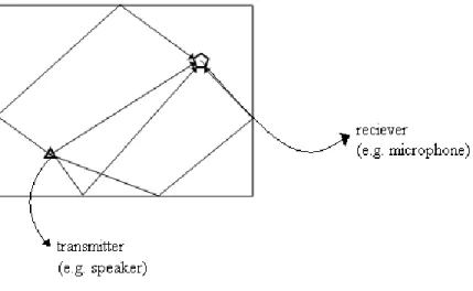
It is a widely used effect. Reverb gives the listener a room perception and as a result simulates the actual reverb one might experience in a closed-space environment. It in fact adds the multiple reflections from the room walls as an actual wave sound travels back and forth in a closed-space environment. Reverberation characteristics in real world are hugely dependant on the size of the room, wall material as well as items which are located inside the room e.g. furniture. Thus, it can easily be concluded that reverb is an important part in the 3D Audio sound experience.
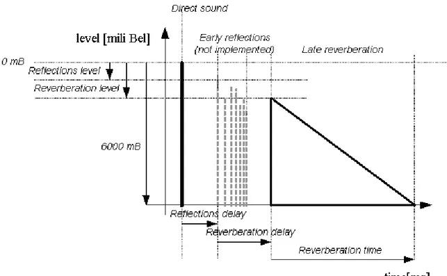
From the source there is normally a direct path to the listener but the sound waves can be reflected from walls and other surfaces in a room to the listener. These waves travel a longer path and arrive at a later time, with less energy. This is shown in Figure 1.2.1, as sound waves may be reflected several times before reaching the listener, the reflections attenuate over time. The reflections are divided in early reflections and late reflections. The early reflections are direct reflections with a higher energy. They also have a direction. The early reflections usually are not implemented due to their complexity and as a result the imitated room is spherical. The late reflections have a denser characteristic with lower energy.
The reverberation time (the time between a direct-path waveform and the last hearable reflection) depends on the size of the room and surface material of the room. Various materials also reflect certain frequencies differently which means they can have high-pass or low-pass characteristics.
time Early
reflections Late reflections
Figure 1.2.1: Early versus late reflections
1.3 Reverb in R13
Reverb in R13 is composed of individual filter parts. These filters shape the output signal when combined in an appropriate order. However, their combination as whole is of no interest in this thesis rather the performance of its individual filters are important. As stated previously, the thesis intention is to optimize kernel processing parts while compiler takes over the general set-up as well as flow control parts written in C. To address this thesis results more precisely, individual filter parts are described and analysed in detail. The following is the description of the main components in Reverb in R13.
1.3.1 Comb filters
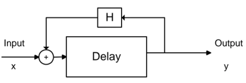
Comb Filters have comb-like notches in their frequency response which results in a shape similar to a comb. The main parts of a comb filter are a relatively large delay element as well as an IIR filter in the feedback part. This IIR filter is a one-pole filter which could have low-pass or high-low-pass characteristics.
Delay
Input Output
+
H
x y
Figure 1.3.1: A typical Comb filter
Due to the fact that Comb Filters are IIR filters, any implementation of them in practice is basically approximation of their impulse response which in other words means truncation of impulse response. As a result, the truncated impulse response has a non-ideal comb-like shape in its frequency response. One proposed way to compensate for the above artifact is to use a number of comb filters in parallel in which delay length is preferable a prime number. It has been proved (according to the internal investigations done at Ericsson Research) that this solution compensates for the overall inconsistent frequency response to some degree specially when combined with the rest of filters in the Reverb implementation. Moreover, it is also proved that by increasing the number of parallel comb filters, the output approaches that of an ideal filter without truncation.
1.3.2 All-Pass filters
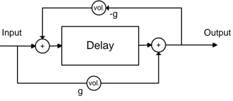
There are a number of all-pass filters present in R13. All-Pass filters pass all frequencies equally and as a result they do not shape the spectra. Besides, they have a phase shift effect that is responsible for changing the sound density.
Delay Input Output + vol. vol. + -g g
Figure 1.3.2: A typical All-Pass filter
All-pass filters have the same non-ideal characteristics as comb-filters when truncated. Similarly, it is advantageous to use a number of them to compensate for the truncation. In that case, the individual delay lengths will also be prime numbers.
1.4 Reverb in R15
Reverb in R15 is enjoying the application of a modified Moorer algorithm. This new algorithm has proved to provide much higher quality and is a huge improvement over R13. In contrast to R13, Reverb in R15 is composed of two parts, Early Reverb and Late Reverb. Early Reverb is quite a new concept in R15 which simulates the reflections from objects inside the room (e.g. furniture). These Early Reflections arrive to the listener within 30 ms after the direct sound. Simulating the early reflections properly results in a more real-world like sound experience and one of the most important properties of the early reverberation is that it increases audio externalization when listening through headphones. Most previously developed early reflection algorithms have concentrated on simulating the reflections from the walls, the floor and the ceiling of a room, thus ignoring the reflections from other objects in a room such as tables and chairs. It has been shown though, that the reflections from objects between the sound source and the listener are most important to simulate and that the room’s size can instead be simulated by a late reverberation algorithm. Therefore, the algorithm described here concentrates on simulating reflections from objects between the sound source and the listener.
1.4.1 The Early Reverberation Algorithm
Due to the fact that early reverb didn’t exist in the R13 implementation, the requirement for analysis of its filter parts was waived in this report and there is no need to cover its structure in detail. The early reverberation algorithm, however, improves as much the quality as it adds to its complexity. Implementation of this part exploits a relatively huge amount of CPU power.
1.4.2 The late reverberation algorithm
Ignoring introduction of a new filter named Room filter, the late reverberation as it is in R15 very much takes after its counterpart in R13 when individual filter components are taken into consideration. The above fact provided us with the opportunity to compare the implementations in R13 and R15 considering execution time, etc. Although not covered by this thesis, future analysis could be carried out to obtain a thorough comparison of Reverb in R13 and R15 thanks to the inherent similarity between Reverb in R13 and Later Reverb in R15.
Although the primary objective was to compare the common components in both versions, a number of other useful filter structures could also be probed due to their wide applications as well as usefulness. Among these filters the one-pole IIR (Room Filter in R15), Biquad as well as FIR filters could be mentioned.
1.4.3 Primary features and applications
The Late Reverb algorithm comes with mono and stereo output capacity. There is also a possibility to mix the amount of dry (unprocessed) and wet (processed) signal in the output to achieve a pleasant reverb level. This can be easily adjusted through user set-up.
One of the main applications of Reverb (both Early and Late) is 3D audio simulation. Reverb comprises the focal point of such algorithms to achieve near-real experience in rendering 3D audio.
Chapter 2
2.1 Digital Signal Processors (DSP)
“A digital signal processor frequently referred to as DSP is a type of microprocessor - one that is incredibly fast and powerful. A DSP is unique because it processes data in real time. This real-time capability makes a DSP perfect for applications where we won't tolerate any delays.” [3]
DSPs usually have a Very Large Instruction Word (VLIW) and are dedicated to perform fast and efficient signal processing operations. They are often very task-specific oriented. Their design supports powerful MACs (Multiply and Accumulate) which are integral parts of a DSP algorithm. Their fast and efficient processing capability doesn’t come for free. DSPs usually occupy a large portion of silicon area and generally need its own dedicated memory. The memory is usually a zero-wait state memory which is a key requirement for processing residing data directly in memory (the main principle behind how DSPs manipulate data). Poor and restricted memory management has often been considered a drawback for DSPs. This is usually in contradiction with general purpose processors which can share common memory architecture and usually have powerful and flexible memory management units. DSPs also have a complex multi-stage/parallel pipeline structure which is tailored to the needs of a fast real-time signal processing application. Thanks to their specific design, they can carry out multiple operations at one clock cycle. DSPs could have high power consumption and are applied in critically demanding DSP applications like Radar/Sonar, medical devices, etc. Although their performance nominates them as good candidates in other consumer products like iPods, cell phones, etc., their inherent constraints limit their wide application in such areas. Large corporations with large scale production prefer solutions which cost less and provide a moderate alternative to DSPs while their application is inevitable in numerous places. In many occasions, companies like EMP (Ericsson Mobile Platforms) have had no choice but to use DSP in critical parts of the platform due to their powerful real-time Digital Signal Processing features.
Many companies have designed and manufactured DSPs. For instance, DSP chipsets manufactured by Texas Instruments as well as Analogue Devices are quite popular and well-known in the DSP literature. Among the DSP series manufactured by TI (Texas Instruments) TMS320xxx and among those manufactured by Analogue Devices ADSP-21xx are quite well-known and widely used in many applications. Another company which has attracted the attention and interest of many big customers (known by their embedded system design), is Ceva. As the name implies their DSPs are named after the company, Ceva DSPs. One specific and actually really interesting point about Ceva as a company is that they provide DSP IP (Intellectual Property) block solutions. This is in contrast to many big DSP manufacturers which provide the already-made silicon solution. IP blocks provide a really flexible solution to embedded system design since customers can enjoy the liberty of applying them in their designs and freely choose the silicon fabrication solution themselves.
2.2 General Purpose Processors
The word General Purpose Processors is referred to all microprocessors other than DSPs. However, microprocessors are also classified into sub groups with each one having a specific set of features. In fact, microprocessors are grouped into embedded processors and general purpose processors which are of course different from the general term microcontrollers. A microcontroller is in fact a computer residing on a silicon chip. It encompasses all necessary parts (including the memory) all in one IC package. A microcontroller generally has the main CPU core, ROM/EPROM/EEPROM/FLASH, RAM and some other essential functions (like timers and I/O controllers) all integrated into one single chip. The main motive behind the microcontroller was to restrict the capabilities of the CPU itself, allowing a thorough computer (memory, I/O, interrupts, etc) to fit on the available silicon solution. Microcontrollers are typically used where processing power is of no crucial importance and are typically used for low-end applications.
On the other hand, a General Purpose Processor (CPU) has much higher computational power but also encompass some peripheral parts like internal memory, I/O controller, etc. They occupy larger silicon area when compared to Microcontrollers and are much more expensive. They are intended for much larger range of applications and they are used for example in a PC where many different applications can be just loaded and run. They have the flexibility to get connected to many different peripherals. To sum up, they are designed for general purpose applications.
There are also embedded processors on which embedded systems are built. Embedded systems are intended for specific applications. For instance, an MP3 player, iPod or cell phone is an embedded system while a PC is a general purpose system. In embedded systems, designer can optimize, improve and reduce size and cost. They are designed to be optimized and tailored to a specific application. On the other hand, general purpose systems are designed to carry out a wide spectrum of general purpose tasks and operations. Naturally, microprocessors are also designed to be used in a specific purpose application (e.g. ARM processors) or in general purpose applications ( e.g. Intel CPUs).
Although microprocessors are much faster than most microcontrollers, they are still slower than their DSP counter parts for signal processing applications. In fact, microprocessors are designed to provide more flexible alternatives from the point of memory, I/O, etc. but they usually don’t have the same computational power when compared to their DSP counter parts. However, they have many advantages that make them appropriate for a wide range of applications. If one could find a microprocessor to satisfy the needs of his application, he might not choose a DSP for the same purpose. In other words, microprocessors are designed for diversity while DSPs are designed for specialty. Yet, there are numerous choices of different silicon solutions as well as applications. At the end, it is the designer who chooses the solution that fits his design criteria.
2.3 RISC processors versus CISC processors
RISC(Reduced Instruction Set Computing) is a design philosophy aimed at delivering simple but powerful instructions that execute within a single cycle at high clock speeds [1]. RISC concept is evolved around compact instruction sets which are fixed in size and make the hardware structure fairly simpler when compared to CISC (Complex Instruction Set Computing). However, it imposes more demand on the compiler and software optimization. Its unique structure makes it flexible for optimization purposes and it is often the programmer’s expertise which plays the key role in comparison with the hardware cost.
The following features are associated with a RISC processor,
1- Reduced Instruction Set: RISC concept imposes the instructions to be of a fixed size while the instructions are of variable size in CISC. The fixed size concept makes the instructions run at roughly one clock cycle and makes pipelining a feasible approach. Contrary, CISC instructions run at more than one clock cycle.
2- Pipeline structure: Pipeline is a concept original to RISC processors. Instructions are fetched and decoded step by step in each pipeline step. The pipeline stage advances one step per clock cycle. Yet, in CISC microcode idea is behind decode and execute. Microcode is itself a mini-program.
3- Register set: RISC processors have a large number of general purpose registers in which both address and data could be stored. In contrast, CISC works on special purpose register for every specific operation. One might easily comprehend this difference if one has been involved in program development for 8086 family of processors.
4- Load/Store idea: one of the main features of RISC processors which by many users is considered a major disadvantage is the fact that data should be loaded into registers for manipulation. Otherwise, no processing is allowed on data. Quite contrary, CISC processors process data while they reside in memory locations and they generally lift this requirement that data should be first loaded into a register.
To summarize, RISC processors need a high clock rate for execution of a typical program when compared to CISC. Yet, RISC provides a much simpler alternative from hardware complexity point of view which results in smaller silicon area as well as lower power consumption.
2.4.1 The ARM architecture concept
ARM processors are a family of RISC processors designed by ARM which are targeted at specific applications encompassing special features. These features have driven ARM towards the following orientations:
1- ARM has a compact instruction set. This makes the code memory space as small as possible. In consumer products like cameras, cell phones, etc. the least amount of memory is desired. As a result, the amount of memory usage is reduced which means
a considerable cost saving for the company. Generally, memory is expensive and intentions are to reduce its size on embedded devices as much as possible.
2- ARM design has moved towards a small silicon area which means ARM processors occupy very small die area. That makes them perfect for small scale consumer products.
3- ARM processors use slow low-cost memory solutions. This feature finds crucial importance when the scale of production is taken into consideration. In contrast, DSPs use zero-wait state memory which turns out to be quite expensive.
4- ARM has made it feasible to debug the hardware within the processor. This makes the program flow and execution transparent to the programmer. In fact it makes it much easier for programmer to debug the program during execution.
Specific features to ARM which are different from embedded processor concept:
1- Not all ARM instructions run at one clock cycle. This is contrary to RISC concept. This feature has better efficiency for certain Load/Store instructions.
2- ARM processors have an inline barrel shifter attached to ALU. This feature brings about implementation of more complex instructions with higher efficiency.
3- Thumb 16-bit instruction set: ARM is generally a 32-bit architecture. However, to make instructions more compact and reduce the code density, ARM has come up with a dense instruction set called thumb which is sometimes up to 30% denser than 32-bit instructions. However, they have lower flexibility and generally take more clock cycles to execute.
4- All ARM instructions are conditional instructions. That means there is an option to run them based on a specific conditional flag e.g. in the event of overflow.
5- Enhanced instructions set: ARM has gradually evolved towards a microprocessor having DSP capabilities. New DSP instruction sets have provided ARM with a huge computational power which in many cases lifts the requirement for application of bulky expensive DSPs. In one of its recent structures, ARM is using 16 and 32-bit multipliers and fast MACs units. Thanks to VFP coprocessor Floating Point operations are now much more efficient.
2.4.2 ARM processor Fundamentals 2.4.2.1 Registers
ARM is a 32-bit architecture. Its register bank has sixteen 32-bit general registers in one specific mode. ARM processor can work in seven different modes (reader is encouraged to refer to ARM architecture reference manual [2] for more information). In any mode, there are up to eighteen active registers among which 16 are general purpose registers visible to programmers as r0-r15 while there are two processor status registers. Three of the general purpose registers (r13-r15) have particular tasks and as a result are known by specific names,
a) r13 is named sp and is used as the stack pointer.
b) r14 is called lr (link register) in which the return address from a subroutine is placed. c) r15 is the PC (Program Counter) and points to the next instruction to be executed.
One could use r13-r14 as general purpose registers but care should be taken because the program should not rely on them as they are particularly dedicated registers for their intended tasks.
The processor status register contains many fields for configuration and program flow control. For instance the processor mode flags or condition flags are placed in this register.
2.4.2.2 Pipeline
“A pipeline is the core mechanism a RISC processor uses to execute instructions. Using a pipeline speeds up execution by fetching the next instruction while other instructions are being decoded and executed” [1].
Pipeline stages evolve along processor improvement. For instance there were 5 pipeline stages in ARM9 (a member of ARMv5 family of processors) while the pipeline structure is composed of 8 stages in ARM11 (a member of ARMv6 family of processors). A more complicated pipeline structure can increase the throughput but it also brings about more latency cost. Yet, more pipeline stages make it possible to run more advanced instructions at a reasonable number of clock cycles and lift the requirement for execution of extra instruction to perform the same task. It also comes with other disadvantages for the programmer. Optimizing code for a CPU with longer pipeline is more challenging and requires much more effort.
2.4.2.3 Exceptions, interrupts and the vector table
When ARM processor encounters an interrupt or exception, PC is set to jump to a specific memory address. The address has a specific range and lies in a region called vector table. The entities in this table are actually instructions which point to a particular routine which is designed to handle the interrupt or exception. This routine is generally called interrupt/exception handler.
ARM processors are wrapped around three basic principles which constitute the core processor while each family extends its functionality by providing specific additions on the top of these concepts. These three central concepts are:
a) cache and tightly coupled memory b) memory management
c) coprocessor interface
These three principles are adopted in different versions around which each specific family is structured.
2.4.3 Architecture revisions
Every revision in ARM family of processors comes with a specific instruction set architecture (ISA). While ISA is tailored to that specific architecture which ARM was wrapped around it is also forward compatible with future ARM revisions. No one would like to have a code which only runs on one particular target and not on its future revisions.
An ARM processor is usually identified by the following standard [1],
ARM [x][y][z][T][D][M][I][E][J][F][-S]
x-family
y-memory management/protection
z-cache
T-Thumb 16-bit decoder
D-JTAG debugger
M-fast multiplier
I-Embedded ICE macrocell
E-enhanced instructions
J-Jazelle
F-vector floating point unit
S-synthesizable version
2.5 ARMv6 family of processors
ARM technology has been used in a diverse set of products. ARM processors have been the dominant processors used in portable and mobile computing products. Their application has grown drastically over recent years and as a result new demands are constantly put on ARM to provide more computational power and flexibility to customers. New demands in market are not restricted to the above mentioned facts. They also cover areas like DSP performance requirements, interworking, mixed-endian support, multiprocessing capabilities, etc. Probably the most interesting improvement in ARM processors has been introduction of media processing instructions for performing Auido/Video processing.
ARMv6 processors also came with a considerable change and improvement in their architecture. The pipeline stages were stretched to 8 stages. Expanded pipeline stages
allowed the execution of fast efficient saturating instructions. Meanwhile, new efficient instructions were introduced which improved ARM efficiency beyond its limits. Among the new features/improvements introduced in AMRv6, the following could be mentioned,
2.5.1 Memory management
Memory management and bus architecture has been revised and optimized in this version. New memory management improvements itself is considered to be responsible for boosting the system performance for as much as 30%.[4]
2.5.2 Multiprocessing
Due to application requirements, there is a great need for driving the processors to incorporate advanced multi processor support. Today’s wireless platforms specially require the multiprocessing between several ARM and DSP processors. The new architecture in ARMv6 has moved this capability beyond its limits. In numerous designs and products many companies like EMP spread access and application modules across multiple CPUs and DSPs and as a result its imperative that they have the ability for multiprocessing.
2.5.3 Media processing
To address the new challenges in market and in order to continue its dominance over low-power portable devices market, ARM has come up with new genuine architectures. ARMv6 was considered a huge architectural revision in many aspects especially in media processing capabilities. Two specific new features were introduced in this family that could boost the DSP performance and nearly satisfy the majority of DSP requirements while eliminating the essence of secondary companion chips.
2.5.4 Data handling
The new mixed-endian support in ARMv6 enables interaction of various endian systems to coexist and communicate over ARM. With increasing system-on-chip integration, it is more likely that little-endian and big-endian systems coexist together. ARMv6 is able to communicate with both and address the needs of both standards through its mixed-endian support.
ARM has also made it more efficient to handle unaligned data. DSP implementations can manipulate unaligned data in ARMv6. This new feature is tightly coupled with SIMD instructions. In fact, unaligned data access enables the programmer to consecutively load the famous Q15 or Q7 fixed-point data into registers while they are already packed. Otherwise, it was required to spend a number of extra cycles to pack the data together by the newly introduced packing instructions.
The above mentioned facts were the main features of improvements provided in ARMv6 while numerous other revisions are made in other different aspects. However, the main improvement which was of our primary interest in DSP implementation was the introduction
of Single Instruction Multiple Data (SIMD) instructions as well as application of Vector Floating Point (VFP) coprocessor.
2.5.5 SIMD instructions [1]
Many DSP applications like audio/video processing algorithms are math-intensive routines. These routines need a large subset of instructions as well as memory access requests to execute. ARM development team was working with the idea of introducing new instructions set that has high code density while maintaining low-power consumption. Eventually, they came up with the idea of SIMD instructions. Since the code density is high while the number of required instructions for a specific routine is kept low, memory system access request falls. This in turn causes lower power consumption in the system. SIMD instructions in effect cut the existing ARM 32-bit data path into 16-bit or 8-bit slices. As a result, operations can be carried out on two 16-bit data or four 8-bit data held in one single register. Applications can consequently enjoy instructions which can work with more than 4 data sets per instruction. This can in effect increase the performance of DSP instructions up to 2, 3 times.
Revising ARM to provide SIMD capabilities, as many as 60 new SIMD instructions were introduced which provided the possibility to perform a wide range of operations among which one could mention,
1- Packing instructions: Thanks to new architecture, ARMv6 processors can construct new 32-bit packed data from pairs of 16-bit data or sets of 8-bit data held in different source registers. The second operand in these instructions can be shifted which can provide the programmer with much more flexibility. Consequently, two 16-bit or four 8-bit data sets can be encapsulated in one single register.
2- Complex arithmetic support: due to addition of many more multiplication instructions which specifically enjoy SIMD features, it is easier and more efficient to perform complicated signal processing operations like filter implementation or transforms like FFT. Besides, a particularly new feature has been provided in ARMv6 which is dual 16-bit multiply instruction support. Now it is feasible to carry out dual 16 16 bit multiply which could be followed by a 32-bit accumulate (done in one instruction) which is a huge success in boosting DSP applications. 3- Saturating instructions (saturating arithmetic): saturating arithmetic was first
introduced in E extensions of ARMv5. However, they were restricted in number and operation. In ARMv6, saturating arithmetic operations are expanded and they are applied to many SIMD instructions as well. It is possible to perform many saturating arithmetic operations on both 32-bit as well as 16-bit data. DSP programmers and implementers are well aware of the fact that saturating operations are central in fixed-point implementations.
4- SAD (Sum of Absolute Difference) instructions: these instructions are provided to compute the absolute difference between 8-bit values and are extensively used in motion video compression algorithms.
2.5.6 Introduction of Vector Floating Point (VFP) coprocessor
ARMv6 optionally comes with a VFP coprocessor which for the first time enables ARM to perform floating-point arithmetic on a dedicated coprocessor. Previously, the most common way to have floating-point implementations was to do emulation by software. Although some variants of recently introduced processors could come with optional floating-point capability, they were never considered a fast and efficient alternative due to their inherent hardware structure. Meanwhile, software implementation of floating-point was an extremely inefficient approach and was almost never referenced in applications except places where single computations like estimating coefficients (with high precision during set-up) were desired. However, ARMv6 has made it possible to do fast and efficient floating-point operations in real-time. Surprisingly, this new feature is extremely powerful and can support Vector-Vector operations, a feature which is not usually expected for the first release. Floating-point operation in ARMv6 is wrapped around VFP11 revision and has the following main characteristics, [5]
1-Operations are consistent with IEEE 754 standard for performing floating-point arithmetic. The only operations which are not supported are,
a- Remainder operation b- Binary-decimal conversion
c- Rounding the floating point number to an integer value
2- Manipulation of single and double precision data.
3- Hardware divide and square root operations.
4- Low-power consumption. ARM claims the VFP coprocessor is a low-power solution but intriguingly there is no figure implying the precise amount of power consumption.
5- Providing three separate instruction pipelines:
– FMAC (multiply and accumulate) – DS (Divide and Square root) – LS (Load/Store)
6- Execution of short vector instructions of up to 8 operations on single precision and 4 operations on double precision data.
7- Parallel execution of ARM and VFP instructions. The vector operations seem like a one-cycle instruction to core processor (They take many clock cycles to be executed inside Coprocessor)
The three separate instruction pipelines share the first two stages (decode and issues) and make it possible to execute many operations virtually at one clock cycle. Imagine a scenario in which a vector operation is issued and passed to FMAC pipeline while a vector data
transfer instruction follows right after. Careful and professional programming can arrange such scheduling in many locations inside a program.
The VFP coprocessor operates as a standalone unit having its own Load/Store and data transfer instructions while effectively communicates with the core processor. It has made it possible to transfer data between core processor registers and internally managed registers. Due to its independent pipeline structure and program flow control, floating point operations appear as one clock cycle instructions to the core processor. That means the core processor can effectively execute and follow its own program flow and routines right after issuing the instruction to VFP coprocessor. In other words, it doesn’t need to wait for the coprocessor result. With careful programming, it is possible to have one-cycle executed commands without any extra clock penalty when using VFP coprocessor.
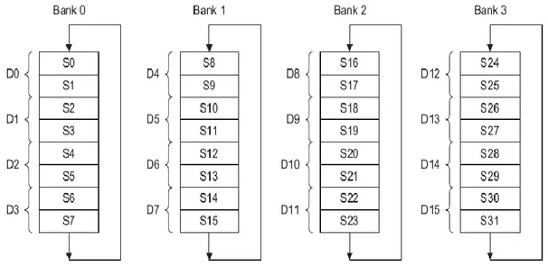
The Vector operation concept is a really genuine efficient idea in VFP coprocessor. This idea enables the coprocessor to work on vectors of data up to 8 samples in length in single-precision mode or vectors of up to 4 samples in length in double-single-precision mode. In addition to vector operations, it is also possible to perform mixed scalar-vector operations in VFP mode. More precisely, the coprocessor can be configured to run in scalar mode only or VFP mode with a specific vector length while it is possible to do scalar-only, vector-vector, mixed scalar-vector operations in VFP mode. There are as many as 32 general purpose registers in VFP coprocessor which are 32-bit in length. Consequently, they can hold 32 single-precision floating-point or 16 double-precision floating-point values. These registers are grouped into four main banks with each bank referenced by a number as follows,
Figure 2.5.1: Register back arrangement in VFP coprocessor
The first bank is referred as scalar bank while others are known as vector banks in general. The banks also act like circular buffers, which basically means they can wrap-up and continue the execution from the beginning of the bank when the pointer reaches the end.
There are rules wrapped around how to perform mixed scalar-vector operations using the above banks. Reader is encouraged to refer to reference literature [5] for further information.
As it is evident from the figure, two subsequent 32-bit registers are merged to make one 64-bit double-precision register. The rules concerned with double-precision operations are similar to their single precision counterparts.
As stated earlier, most of the arithmetic and data transfer operations in the core processor are reflected in VFP coprocessor and are adopted for floating-point operations. It is possible to Load/Store multiple data by one instruction while stack operations are also allowed and carried out with minor restrictions. It is also claimed that the VFP coprocessor is a low power alternative. However, what does this term exactly mean technically remains to be examined in practice on an actual hardware. Undoubtedly, power consumption should be higher for floating-point operations when compared to fixed-point operations. This is mainly due to the fact that floating-point operations involve more gates and need more complicated hardware for implementation.
Due its flexibility, many different filter structures can easily and efficiently be implemented through VFP. IIR and specifically FIR filter implementations are made fast and easy and are no more considered a challenge for ARM. VFP concept is central to future revisions of ARM family and is even embedded with fixed-point idea in Cortex processors.
2.6 ARM1176jzfs processor
ARMv6 family of processors comes with a number of variants. They mainly cover two specific processors. One is known by generic ARM1136jf-s and the other one is ARM1176jzf-s. The main difference between these two processors is in areas other than pipeline structure and new media processing capabilities. In fact, these two features are central to ARMv6 core and are the same for all family members regardless of its version. Yet, there are some main differences between these two processors among which one could mention power management scheme, TrustZone, smart cache, DAM, etc. Reader is encouraged to refer to reference literature [5].
As the generic name implies, ARM1176jzf-s is a member of ARMv6 family (ARM11), it has Jazelle technology and encompasses VFP coprocessor.
All the simulations and implementations done in this thesis work were carried out on an ARM1176jzf-s processor.
Chapter 3
3.1 DSP algorithm implementation and optimization
One may be familiar with mp3 players, digital cameras, cell phones and many other digital products which incorporate simple as well as advanced signal processing algorithms to perform their intended applications. Nowadays, digital circuits and microprocessors wield enough computational power to address the needs of real-time digital signal processing applications.
Implementing digital signal processing algorithms in general is a challenging task especially when hardware constraints are taken into consideration. It is not always possible to implement an algorithm with as much precision as desired. Besides, the execution time for algorithms should also be taken into consideration. Many advanced DSP algorithms are never implemented and used in practice simply because there is no hardware which is capable of executing them in real-time or in a reasonable time length. On the other hand, memory efficiency is another major factor which plays a crucial role when implementing these algorithms. Memory usually occupies a large portion of silicon area and is expensive. As a result, intentions are usually to allocate the least possible amount of memory to any DSP algorithm. This is the main reason why special care is taken to make the algorithms as memory efficient as possible. When DSP algorithms are to be implemented in digital signal processors, it is desired to have the code occupy a small amount of code area. Thus, the number of instructions describing any algorithm should be kept reasonably small. More importantly, it is desired to reduce the number of memory access (read/write) as low as possible since memory access is accounted for the major amount of power consumption during DSP execution.
On the whole, there exist a couple of choices to implement a DSP algorithm. One is to hardwire the digital circuit corresponding to the intended algorithm. This method is usually performed by an ASIC designer who takes the original algorithm and translates that into hardware language describing them by gates and switches. This way of implementation is considered the fastest (regarding execution time) alternative because as stated above the logical circuit is hardwired and no further translations are required upon execution. However, there are a number of drawbacks. ASIC design is usually an expensive task. Manufacturing the hardware is even more costly. Most importantly, it is not possible to make any changes once the hardware is in place and as a result future modifications are no more feasible. This makes the ASIC design highly dedicated to scenarios which have a wide application and are never to be modified. They are also used when the hardware should be as fast as possible while it should occupy the lowest amount of silicon area. A good example of hardware exploiting this technology is a graphic accelerator chip which is widely used in gaming devices, PCs, etc.
Another alternative is application of FPGAs (Field Programmable Gate Arrays). This evolving hardware technology enables the designer to digitally implement the algorithm described by logic switches while it still gives this flexibility to reconfigure and modify the algorithm at any later time. While this flexibility is a huge success in hardwiring DSP algorithms it is still far from being optimal for many applications. First, due to its inherent structure a large silicon area is occupied. Second, the power consumption is just too high. Third, the price which is a crucial factor is also high for high-volume production when compared to other choices. The last but not the least, the execution time for an FPGA implemented algorithm is longer than a typical hardwired logic circuit. Yet, it is the implementer’s choice when a fast hardware with reasonable cost is to be implemented. Specially, this technology is widely used in areas like hardware test in which a final ASIC hardware is simulated on FPGA to find the bugs and do verifications before the final ASIC is manufactured. It is also widely used in research projects where a number of different algorithms are to be implemented and probed in real-time in which hardware reconfiguration is an essential factor.
Two other alternatives are applications of Digital Signal Processors and general-purpose CPUs which were described in detail in the previous chapter. One of the most frequent ways of DSP implementation is through application of general as well as dedicated digital signal processors. Regardless of which processors is chosen, the algorithm should be translated into machine language which is recognizable by that specific processor. Since writing machine code is considered an extremely low-level programming, the programmer needs to take care of the program flow closely which makes code development for large programs a tricky task which is inefficient and time consuming. As a result, compilers were developed which took the program description in a common user friendly programming language like C/C++ and compiled the code into machine language. These compilers facilitated program development as well as algorithm implementation. They also waved the need to machine code one whole program. However, this flexibility doesn’t come for free. Compiling a high level code to machine code (in here assembly language) is an optimization done by the computer which is done based on a number of factors like space, time and memory optimization. While most compilers can be configured to the optimization based on one or more criteria, this optimization is never perfect. Human intelligence can tackle the optimization job in its best ideal way. At the end, compilers are themselves developed by a human operator. Thus, although this compilation is optimal enough for many applications it doesn’t suit the needs of some other. For instance, many real time signal processing applications demand a huge computational power to execute. That means there is a strong need for a hardware which is not only powerful enough to address the needs of the application but it should also enjoy the presence of an ideally optimized program which consumes the least amount of resources from the processor. In other words, a program should be optimized in such a way that its execution is performed with the least number of clock cycles while it enjoys optimization in other areas like memory and power consumption. Observe that power consumption is directly related to execution time but it is also connected to other factors like application of dedicated floating-point hardware or ordinary fixed-point translation, etc.
Considering the above mentioned facts, preference is given to a final implementation which is an optimal combination of compiler optimized code and hand assembly optimized code (in which the kernel parts are optimized). In other words, non-crucial parts of the algorithm are left for the compiler to take care of while critical parts are left to a human programmer to be optimally implemented. These kernel parts are usually those which consume the highest amount of processor resources. Among typical kernel parts one could mention individual filter parts of a DSP algorithm like the ones which were optimized in Reverb. Due the fact that the main computational load of the program is the direct result of filtering operations it is seriously desired to have them hand-optimized and merged into the main program.
3.2 Signal representation
There are generally two ways to represent the signals once the analogue signal is passed through the A/D to be represented in digital format. Digital signals are represented either in fixed-point or floating-point. The choice for representation is wholly dependant on the design criteria, constraints and intended application. In addition to the above factors, there are two main things to be concerned about when representing a signal [1]
1- The Dynamic Range (DR) of the signal which is referred to the maximum fluctuations a typical signal could have and is depicted by the following equation:
( ( )) ( ( )) DRMax x n Min x n
2- The accuracy which is required in the representation. The accuracy in technical terms means how accurate a represented value is to the actual value and is different from precision.
3.2.1 Fixed-point representation
A fixed-point representation uses the application of an integer to represent a fractional value by scaling the fraction. In practice, preference is given to scaling by a number which is a power of two. In this way, one can implement multiplication and division by using shifts. This is consistent with binary point representation in logical circuits in general and makes arithmetic operations much more computationally efficient. In practice, a typical number x with one sign bit, n integer bits and m banal bits is represented as
. Qn m ,
in which Q stands for the sign bit, n represents the number of integer bits while m represents the binal bits. For instance, the following representation stands for a fractional number which is 16 bits long while has one sign bit. Usually two’s complement values are referenced and used.
15 Q
This number represents values in the following range:
1 x 1
which of course will be scaled and treated in fixed-point as
32768 x 32767
Please note that +1 doesn’t have an exact equivalent in the above representation due to the fact that +32767 corresponds to 15
1 2 which is close to 1. This form of representing 16-bit values is one of the most common representations and has wide applications in audio processing cases. Observe that in fixed-point each signal is represented by an integer value and we use the same scaling for the whole signal. This is different from floating-point representation where each signal value has its own scaling called exponent [1]. To sum up, fixed-point representation allows us to cover a range of numbers say,
x
max
x
min with the following resolution [2] max min 1 x x m ,where m2 b is the number of levels while b is the number of bits. A basic characteristic of the fixed-point representation is that the resolution is fixed. Furthermore,
increases in direct proportion to an increase in the dynamic range [2].3.2.2 Floating-point representation
Floating-point representation can be used as a means to cover a larger dynamic range. A typical floating point number consists of the mantissa (m) which represents the fractional part of the number and is multiplied by the exponential factor 2e where e is either a positive or negative number. Thus, the number is
.2e
xm
For more detailed information on floating and fixed-point representations please refer to reference literature [2]. Although floating point representation has a number of advantageous over fixed-point, they are not commonly used in embedded systems and designers are reluctant to use them. This has historically been connected to the limitations that a typical embedded hardware has. Embedded systems usually have a less complicated hardware which is the direct result of requirement for smaller silicon area as well as lower power consumption. These two most critical factors associated with embedded system design has encouraged both hardware and software designers to stick to the simpler and more efficient alternative which is fixed-point representation.
A common mistake is usually to think of floating-point representation providing higher accuracy than fixed-point alternative when the number of equal bits is equal [1]. This way of thinking is completely false due to the fact that for the same number of representation bits a fixed-point representation provides us with higher accuracy than its floating-point counterpart. For instance, a fully scaled 32 bit signed number represented in fixed-point gives a relative error of 231 while the same number of bits in floating-point provides us with a relative error in the amount of224[1]. However, the dynamic range provided by floating-point representation is much larger than fixed-floating-point for the same number of representation bits which easily enables avoidance of saturations. Saturation due to limited dynamic range (an inherent characteristic of fixed-point arithmetic) not only makes coding be more cumbersome but also degrades the Signal to Noise Ratio (SNR) considerably.
To summarise, it is best to use fixed-point when there is a clear bound to the signal while floating- point is preferred when the signal bound is not fully defined. Meanwhile, our choice of either fixed-point or floating-point is dictated by the available hardware constraints as well as other crucial factors like power consumption, etc. If an algorithm should be implemented on a general purpose CPU with no dedicated floating-point hardware, then there is no option left but to do fixed-point implementation or to use software library to emulate floating-point operations. For instance, implementation on ARM family of processors is forced to be in fixed-point in numerous occasions when there is no access to floating-point coprocessor or its equivalence. Even if a dedicated hardware (e.g. VFP coprocessor in ARMv6 CPUs) exists one needs to pay special attention to the execution time, power consumption and other critical factors to forge ahead with the appropriate choice. Most frequent implementations are done in fixed-point and there is a possibility that floating-point will be applied in near future implementations.
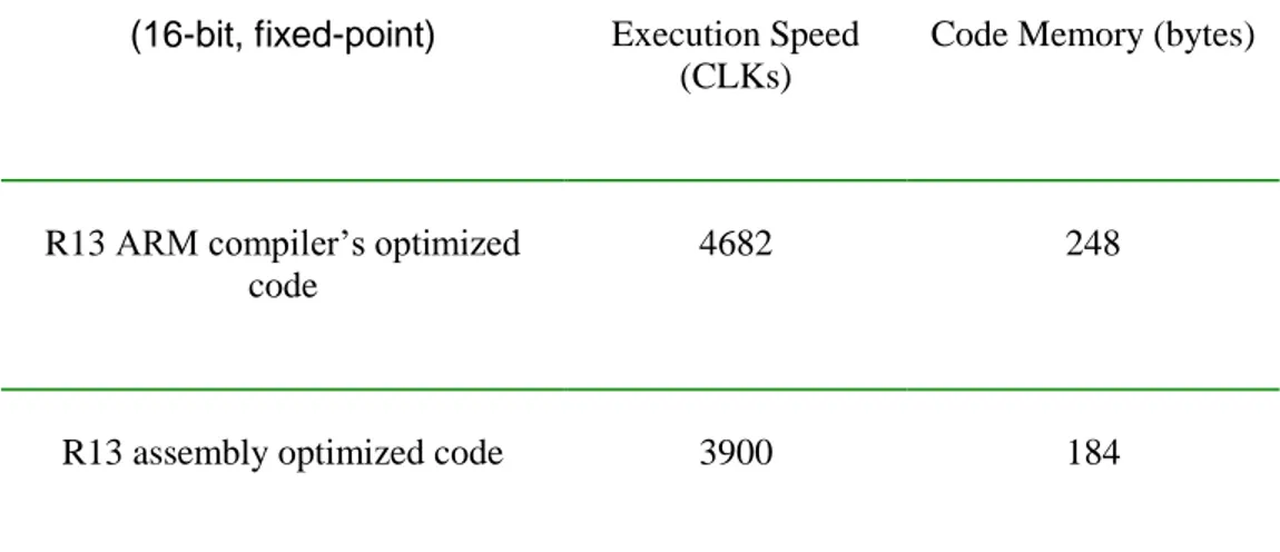
3.3 Reverb implementation in R13
As already described in previous chapters, Reverb algorithm in R13 constitutes a number of individual filters which are combined with a set of specific parameters. The implementation for this algorithm exists both in pure C or combined C/assembly code. The C alternative of course is compiled by ARM compiler to generate the machine code. Yet, as mentioned before this code is not optimized for its intended application. Its execution time is high and the code occupies a large space. Naturally, the kernel parts of the algorithm were assembly optimized. Besides, since the optimization was done by one of the most experienced team members, it could play a solid role as the reference for other comparisons. It is needless to mention that implementation was done in fixed-point since the processor (ARMv5 family of processors) didn’t have any floating-point coprocessor. Besides, fixed-point implementation is still the programmer’s choice because the rest of the platform is based on fixed-point. Moreover, since many filter parts like All-Pass and Comb-Filters are common between Reverb in R13 and R15, R13 implementation played an effective role as a good reference for improvement comparisons.