Research
Report number: 2015:37 ISSN: 2000-0456 Available at www.stralsakerhetsmyndigheten.se
Models for axial relocation of fragmented
and pulverized fuel pellets in distending fuel
rods and its effects on fuel rod heat load
2015:37
Author: Lars Olof Jernkvist Ali Massih
SSM 2015:37
SSM perspective Background
At high burnups the components of the nuclear fuel are affected by the environment they have been exposed to. Fuel pellets can crack due to thermal effects and tensions build up inside because of fission gases. The result of this is that fuel pellets at high burnup in a situation with high temperature increase (for example at a loss of coolant accident) can break up severely and move within the fuel rod, relocate. Relocation of fuel fragments can in turn result in an increased load where frag-ments accumulate and an increased risk of fuel rod failure.
Within the research of fuel behavior supported by OECD/NEA at Studs-vik and Halden phenomena acting in a loss of coolant situation are in focus. These tests are the basis for development of analytical tools that can predict fuel rod behavior and with analytical tools the situation in a nuclear reactor can be analyzed.
Objective
In this project Quantum Technologies AB has developed models for FRAPTRAN-1.5 for fuel fragmentation and relocation and the subse-quent increase of load in the volume where fuel fragments accumulate. The models are novel in the several ways; both as models for fragmenta-tion and relocafragmenta-tion and for the way they are incorporated in the FRAP-TRAN program.
Results
This report describes the development of the new models from the basic theory to experimental observations to the mathematical expressions that can be used in the analytical tool FRAPTRAN. Three major models have been developed; fragmentation of nuclear fuel, axial relocation of the fragments and thermal response of relocation. These models are incorporated in FRAPTRAN in way which makes it possible to calculate the feedback that fragmentation and relocation causes.
To show the capacity of the new models a calculation of one of the LOCA-tests performed in Halden is included in the report, a calculation which shows good agreement with the test.
In this process of code development interpretations of what is seen in the experimental research is vital. The fragmentation and pulverization characteristics are discussed from the point of fragment sizes and shapes and how they can be packed in a confined volume. In combination with typical nuclear fuel burnup behavior it indicates a threshold from where fragmentation and relocation becomes an issue to consider and to limit. The report also discusses how these phenomena degrade the cladding that surrounds the nuclear fuel and how the temperature and oxidation at the hot spot is affected and the time to burst is reduced.
SSM 2015:37
Need for further research
Continued improvement of calculation tools are needed to accurately describe the performance of the nuclear fuel in the reactor at transient and accident conditions. In the conclusions of this report aspects that need to be further developed in analytical tools and the need for more experimental data are described. Further development is necessary for example regarding mechanisms for fragmentation and dispersal as well as the effects of dispersal. There is also a need to use this newly devel-oped model to analyze and interpret other LOCA-tests from Halden and Studsvik.
Project information
Contact person SSM: Anna Alvestav Reference: SSM2014-2355
2015:37
Author:
Date: September 2015
Report number: 2015:37 ISSN: 2000-0456 Available at www.stralsakerhetsmyndigheten.se
Lars Olof Jernkvist, Ali Massih
Quantum Technologies AB, Uppsala
Models for axial relocation of fragmented
and pulverized fuel pellets in distending fuel
rods and its effects on fuel rod heat load
SSM 2015:37
This report concerns a study which has been conducted for the Swedish Radiation Safety Authority, SSM. The conclusions and view-points presented in the report are those of the author/authors and do not necessarily coincide with those of the SSM.
Models for axial relocation of fragmented
and pulverized fuel pellets in distending fuel
rods and its effects on fuel rod heat load
Report TR14-002V1, September 1, 2015
Lars Olof Jernkvist
Ali R. Massih
Quantum Technologies AB
I
Contents
Summary ... III Sammanfattning ... IV 1. Introduction ... 1 2. Model description ... 52.1. Fuel fragment axial relocation ... 5
2.1.1. Fundamental assumptions ... 5
2.1.2. Computational algorithm ... 8
2.2. Fuel fragmentation and pulverization ... 11
2.2.1. Fuel fragmentation ... 11
2.2.2. Fuel pulverization ... 13
2.2.3. Packing fraction of crumbled fuel ... 15
2.2.4. Threshold for fuel fragment detachment ... 20
2.3. Modifications to thermal calculations ... 21
2.3.1. Radial heat conduction equation ... 22
2.3.2. Heat transfer by axial fuel relocation ... 24
2.3.3. Void volume gas temperature calculation ... 25
3. Verification of the relocation model ... 27
3.1. Test case 1: Single balloon ... 27
3.2. Test case 2: Twin balloons ... 30
4. Assessment of Halden LOCA test IFA-650.4 ... 33
4.1. Methodology, computer programs and assumptions ... 33
4.1.1. Simulation of pre-irradiation ... 34
4.1.2. Simulation of LOCA test ... 34
4.2. Calculated results ... 37
4.2.1. Pre-irradiation ... 37
4.2.2. LOCA test ... 39
5. Concluding remarks ... 49
5.1. Distinguishing features of the proposed model ... 49
5.2. Main conclusions ... 50
5.3. Suggestions for further work ... 52
6. References ... 55
Appendix A: Fuel fragmentation and pulverization ... A.1
Appendix B: Effective thermal conductivity of crumbled fuel ... B.1
Appendix C: The Halden LOCA test IFA-650.4 ... C.1
II
III
Summary
Loss-of-coolant accidents (LOCAs) in light water reactors may lead to over-heating of the fuel rods, significant distension of the cladding tubes and axial relo-cation of fuel pellet fragments inside the “ballooned” part of the fuel rods. The fuel relocation may localize the heat load to a particular part of the rod, there-by increasing the risk for cladding failure and aggravating local oxidation of the cladding. It may also increase the amount of fuel dispersed into the coolant, should the cladding fail. Recent LOCA tests have revived interest in the relocation and dispersion phenomena among nuclear regulators, since the test results suggest that high burnup (> 65 MWd/kgU) UO2 fuel pellets may pulverize into very fine
(< 0.2 mm) fragments, with a higher potential for axial relocation and subsequent dispersal than observed earlier for low to medium burnup fuel.
To analyse these issues, a computational model for axial relocation of fuel frag-ments during LOCA and its effects on the fuel rod heat load and failure processes is developed and introduced in SSM’s version of FRAPTRAN-1.5, a computer program intended for fuel rod thermo-mechanical analyses of transients and acci-dents. The fuel relocation is calculated on the basis of estimated fuel fragment size distributions and the calculated cladding distension along the fuel rod, and its ef-fects on the axial redistribution of stored heat and power are accounted for in thermo-mechanical analyses of the fuel rod. Hence, our model fully considers thermal feedback effects from the fuel relocation, in contrast to existing relocation models. It also provides estimates of the amount of fuel that may potentially be ejected into the coolant upon cladding failure anywhere along the fuel rod.
The model is validated by comparisons with measured data and discussed in light of tests and experiments. In particular, we study the IFA-650.4 integral LOCA test in the Halden reactor, Norway. This test was done on a very high burnup (92.3 MWd/kgU) UO2 fuel rodlet and it resulted in extensive fuel pulverization, axial
relocation and fuel dispersal into the coolant. Our simulations of this test suggest that thermal feedback effects from axial fuel relocation are strong enough to sig-nificantly affect the dynamics of cladding ballooning and rupture, even though the calculated duration of these processes is no more than 7–8 seconds. Moreover, for the considered LOCA test, the axial relocation has a strong effect on the calculat-ed peak cladding temperature and oxidation after rupture.
Finally, our work suggests that the aforementioned pulverization mechanism of high burnup fuel is important to axial fuel relocation during LOCA as it may in-crease the packing fraction of crumbled fuel. The pulverization thereby eases axial movements of the fuel pellet column and raises the local heat load in regions where fuel fragments accumulate. Our calculations indicate that fuel with a pellet average burnup around 70–75 MWd/kgU would be particularly prone to axial relocation, due to its expected fragment size distribution.
IV
Sammanfattning
Haverifall med kylmedelsförlust (LOCA) i lättvattenreaktorer kan leda till överhettning av bränslestavar, utvidgning av stavarnas kapslingsrör, samt axiell omflyttning av brän-slekutsfragment i de delar av stavarna som expanderat. Bränsleomflyttningen kan kon-centrera värmebelastningen till en begränsad del av stavarna och därigenom öka risken för kapslingsskador och förvärra kapslingsrörens oxidation lokalt. Den kan också medföra att mängden bränsle som sprids ut i kylvattnet ökar i händelse av kapslingsskada. Nyligen genomförda LOCA-experiment har återuppväckt tillsynsmyndigheternas intresse för dessa fenomen, då provresultaten antyder att högutbränt (> 65 MWd/kgU) UO2 -bränsle kan pulveriseras till mycket små (< 0.2 mm) fragment, vilket leder till en större risk för omflyttning och efterföljande utspridning i kylvattnet än vad som tidigare observerats för bränsle med låg eller medelhög utbränning.
För att analysera dessa frågor utvecklas här en beräkningsmodell för axiell omflyttning av bränslefragment under LOCA och dess effekter på bränslestavens värmebelastning och skadeprocesser. Modellen införs i SSM:s version av FRAPTRAN-1.5, ett beräknings-program avsett för termomekanisk analys av bränslestavar under transienter och olyckor. Bränsleomflyttningen beräknas på grundval av uppskattad storleksfördelning för bränsle-fragmenten samt kapslingsrörets beräknade deformationsprofil längs bränslestaven, och bränsleomflyttningens inverkan på axiell omfördelning av effekt och lagrad värme beaktas i termomekaniska analyser av bränslestaven. Vår modell tar således full hänsyn till termiska återkopplingseffekter av bränsleomflyttningen, i motsats till existerande beräkningsmodeller. Den tillhandahåller även uppskattningar av den bränslemängd som potentiellt kan spridas ut i kylvattnet vid kapslingsbrott i någon del av staven.
Modellen valideras genom jämförelser mot mätdata och diskuteras mot bakgrund av experimentella resultat. I synnerhet studerar vi LOCA-experiment IFA-650.4, som genomförts i Haldenreaktorn, Norge. Provet gjordes på en högutbränd (92.3 MWd/kgU) UO2-provstav, och resulterade i omfattande bränslepulverisering, axiell omflyttning och bränsleutspridning i kylvattnet. Våra simuleringar av detta prov antyder att termiska återkopplingseffekter från den axiella bränsleomflyttningen är tillräckligt starka för att märkbart påverka dynamiken för kapslingens deformation och brott, trots att den beräknade varaktigheten hos dessa processer är högst 7–8 sekunder. Dessutom har den axiella bränsleomflyttningen stor inverkan på kapslingens beräknade maximala temperatur och oxidation efter kapslingsbrottet för det beaktade LOCA-experimentet. Avslutningsvis skall nämnas att vårt arbete pekar mot att ovan nämnda pulveriserings-mekanism för högutbränt bränsle är betydelsefull för axiell bränsleomflyttning, då den kan öka bränslefragmentens packningstäthet. Pulveriseringen underlättar därmed axiella rörelser hos bränslekutspelaren och ökar den lokala värmebelastningen i områden där kutsfragment ansamlas. Våra beräkningar antyder att bränsle med en genomsnittlig kutsutbränning runt 70–75 MWd/kgU torde vara särskilt benäget för axiell omflyttning, på grund av dess förväntade fragmentstorleksfördelning.
1
1. Introduction
Axial relocation of oxide fuel fragments inside distending cladding tubes of light water reactor (LWR) fuel rods was first reported about 35 years ago when in-reactor experiments on fuel rod behaviour during loss-of-coolant accidents (LOCAs) were conducted in Germany and the USA [1-4]. Post-test examinations revealed that significant amounts of fuel fragments could relocate and accumulate in ballooned regions of the test rods, provided that the cladding distension was sufficiently large. From these early tests, it was also clear that the fuel relocation could occur both before and concurrently with cladding rupture [1]. The findings raised concern that the relocation would increase the local heat load in ballooned parts of fuel rods, which would then result in higher temperature and faster clad-ding oxidation than normally considered in safety analyses. Some of the earliest computational studies of these potential consequences were in fact carried out in Sweden, and the results were quite alarming [5, 6]. However, in a seminal model-ling work on axial fuel relocation, Siefken [7] stated that ballooning in most cases would lower the cladding temperature. The reason is that disorderly stacked, mm-sized, fuel fragments in the ballooned part of the fuel rod have a fairly low pack-ing fraction, which means that the claddpack-ing tube diameter has to increase signifi-cantly to accommodate additional fuel. As a result, the increase in coolable area caused by the large cladding distension more than compensates for the increased amount of hot fuel within the cladding.
Although axial fuel relocation was still considered an issue by regulators [8, 9], the analysis presented by Siefken in 1983 was reassuring, and little attention was paid to the phenomenon until 2006, when a LOCA test (IFA-650.4) on a very high burnup fuel rod in the Halden reactor, Norway, resulted in cladding rupture with concomitant dispersal of a large amount of fuel fragments into the coolant. Subse-quent post-test examinations revealed that a large part of the fuel pellet column had relocated axially and been ejected into the coolant through the fairly small rupture opening. This kind of behaviour had not been observed in earlier tests, which were limited to fuel rods with burnups lower than 35 MWd(kgU)-1. The IFA-650.4 test was soon followed by similar tests on other high burnup fuel rods, both integral in-reactor LOCA tests in Halden [10] and out-of-reactor LOCA simulation tests in Studsvik, Sweden [11]. These tests have shown that, when overheated, high burnup UO2 fuel may pulverize into very fine (< 0.2 mm)
frag-ments. These fragments seem to have a higher potential for axial relocation and subsequent dispersal into the coolant than the fairly large fuel fragments typically observed in early LOCA tests on low to medium burnup fuel. As will be shown in this report, the fine fragments formed by pulverization of high burnup fuel may also increase the packing fraction of crumbled and relocated fuel in ballooned regions of the fuel rod, which may lead to higher local heat loads than for the coarse fragments typically seen in low burnup fuel. Hence, Siefken’s conclusions do not necessarily hold for high burnup fuel.
2
The observed difference in behaviour between low and high burnup fuel during LOCA has revived interest in the fuel fragmentation, relocation and dispersion phenomena among nuclear regulators [12, 13]. In comparison with the 1980s, the regulatory focus has somewhat shifted from the effects of axial fuel relocation on the local heat load to its effects on fuel dispersal upon cladding rupture. The fuel dispersal is an issue with regard to energetic fuel-coolant interaction, radiological consequences, criticality and long-term coolability of the material ejected into the coolant.
Along with the recent LOCA tests on high-burnup fuel, some computational mod-els have been proposed for the observed fuel relocation. For example, already in 2006, Aounallah and co-workers made some simple estimates of fuel fragment relocation when evaluating the Halden IFA-650.4 test with the FALCON fuel analysis program [14]. A year later, Khvostov et al. [15] presented a more thor-ough analysis of the same test, using FALCON and a simple stand-alone model for assessing the thermal effects caused by the relocation. The IFA-650.4 test was also recently evaluated by Govers and Verwerft, who developed a computational model for axial fuel relocation that they used together with the FRAPTRAN com-puter program [16]. All these relocation models estimated the extent of fuel frag-ment relocation based on the cladding distension along the fuel rod, as calculated with the fuel rod analysis program (FALCON or FRAPTRAN). However, the models were not fully integrated with these programs, and the effects of relocation on the axial redistribution of fuel mass, stored heat and power were only partially accounted for in the thermo-mechanical analyses of the fuel rods.
The computational model for axial fuel relocation presented in this report is im-plemented as an integral part of FRAPTRAN-1.5, a computer program used for fuel rod thermo-mechanical analyses of transients and accidents [17]. Our reloca-tion model is distinguished by its close integrareloca-tion with the solureloca-tion methods for radial heat transfer in this program. Hence, in contrast to hitherto presented relo-cation models, the model considers thermal feedback effects from the fuel reloca-tion in a complete and consistent way. It also uses submodels to calculate the packing fraction and effective thermal conductivity of particle beds formed by crumbled fuel in ballooned regions of the fuel rod, based on the estimated state of fragmentation for the fuel pellets. In particular, these submodels estimate the mass fraction of fine fuel fragments formed by pulverization of overheated high burnup fuel. As already mentioned, the pulverization phenomenon increases the packing fraction of disorderly stacked fuel fragments. This eases axial movement of the fuel, and it also strengthens thermal feedback from the relocation; both effects are considered in our model.
The relocation model and its supporting submodels for the fuel fragment packing fraction, effective thermal conductivity, fuel fragmentation and pulverization, are presented in section 2 of the report. The experimental studies and data, on which the latter models are based, are presented in Appendix A. A separate part of
3
tion 2 is devoted to the modifications made to the equations for radial heat transfer in FRAPTRAN-1.5 in order to account for thermal feedback effects from the fuel relocation and to address the change in fuel geometry from a cylindrical, dense, fuel column to a porous particle bed. In section 3, we apply the model to two sim-ple test cases to verify its correctness and to illustrate its functionality. The model is then validated against the Halden IFA-650.4 LOCA test in section 4, where calculated results are discussed in light of measured data. Finally, in section 5, we draw some general conclusions from the presented study and make suggestions for further work.
5
2. Model description
Three submodels are dealt with in this section. The first and most important treats axial relocation of fuel fragments. This submodel, which is presented in section 2.1, requires input in terms of cladding tube deformations and estimates of the fragment size distribution for the fuel pellet column. The latter are given by sub-models for fuel fragmentation and pulverization, described in section 2.2. The relocation model provides output in terms of the change in fuel mass distribu-tion along the fuel rod. This is used as input to thermal calculadistribu-tions by the host code, in our case FRAPTRAN-1.5 [17], so that the radial heat transfer equation is modified in those parts of the fuel rod where fuel relocation occurs. These modifi-cations are described in section 2.3.
2.1. Fuel fragment axial relocation
2.1.1. Fundamental assumptions
The model is based on two postulated prerequisites for axial relocation of fuel fragments within a distending fuel rod. Firstly, the cladding distension along at least one axial segment of the discretized fuel rod must be sufficient to accommo-date relocated fuel fragments in a disordered (crumbled) configuration, which is assumed to contain a lot more void volume than the original, pellet-like configura-tion. In a specific axial segment of the fuel rod, henceforth referred to by subscript k, the disordered configuration is defined by the packing fraction of fuel frag-ments k f k k V V . (1)
Here, V is the volume occupied by fuel fragments and Vkf k is the total volume
enclosed by the cladding tube in the k:th segment. In an axial segment of length Lk, the total volume is Vk LkRcik2 , where Rcik is the cladding inner radius in the
k:th axial segment. An alternative way of characterizing the crumbled fuel is by the void fraction in the segment, which is simply 1- k.
As already mentioned, kis very close to unity under normal fuel operation, since
the fuel fragments are then densely packed and retained in the original, cylindrical configuration of the pellets. The void volume is then made up essentially of pellet dishes, cracks and possibly a narrow pellet-cladding gap. When the cladding tube distends under LOCA, the gap gradually widens and may reach a size that make the fuel pellet column collapse. The fuel fragments then move radially outward and turn into a disordered pattern with ksignificantly lower than unity. Here, we
make the assumption that local collapse of the fuel pellet column in an axial
6
ment occurs when more fuel can be accommodated in a crumbled configuration than in the original, pellet-like, configuration. This condition on fuel pellet col-umn collapse can be written as
i k M k m m , (2) where i k
m is the initial (as-fabricated) fuel mass in the k:th segment and M k
m is the fuel mass in the segment in case it is completely filled with crumbled fuel:
2 cik k f k k f k M k V L R m . (3)
Here, f is the density of the fuel material and k is the packing fraction of the crumbled fuel. We treat this packing fraction as a model parameter that is inde-pendent of the cladding distension. Hence, when fuel relocates from higher eleva-tions, the packing fraction of disordered fragments in ballooned segments that receive fuel is assumed to remain equal to the packing fraction just after fuel col-umn radial collapse. This assumption is justified by the early work of Siefken [7], who measured the packing fraction of crumbled fuel in eight ballooned fuel rods with low (< 17 MWd(kgU)-1) burnup after LOCA tests in the Power Burst Facility
(PBF) reactor, USA. He found that the packing fraction in regions where the fuel pellet column had collapsed into a crumbled state did not change much as the cladding tube continued to distend [7]. In our model, it is assumed that this char-acteristic packing fraction of disordered fuel fragments, which is a key model pa-rameter, depends on the fragment size distribution of the fuel. This, in turn, de-pends on burnup and operating life of the fuel. From theory and experiments, the packing fraction is expected to be fairly low (0.6–0.7) for low burnup fuel that contains mostly mm-sized fragments. It is expected to be higher for higher burnup fuel, which contains some amount of much finer fragments that will fill up the gaps between the larger fragments and between the fragments and the cladding inner surface. The method for calculating kfrom the state of fuel fragmentation is defined in section 2.2.3.
The condition on fuel pellet column collapse defined by eqs. (2) and (3) will pre-clude axial relocation until the cladding radius in some axial segment reaches a threshold deformation, roughly given by 2 ( ) 2 (0)
cik cik
kR t R
, where the right-hand-side quantity is the as-fabricated cladding inner radius. In terms of cladding hoop logarithmic strain, (t) ln(Rcik(t)/Rcik(0)), the condition for relocation can thus be written 2 ) ( ln ) ( ) (t th t k , (4) where th
can be interpreted as a cladding threshold strain (logarithmic) for fuel pellet column collapse and onset of fuel fragment axial relocation. Equation (4) is plotted in Fig. 1. It is clear that the threshold strain is sensitive to the value as-sumed for the packing fraction of crumbled fuel.
Equation (4) defines a necessary condition on the cladding hoop strain for fuel fragments that fall down from higher elevations of the fuel pellet column to be accommodated in a disordered configuration within a ballooned segment of the
7
fuel rod. The second prerequisite for axial relocation is given by the fact that no fragments will detach and fall down, unless the cladding tube is sufficiently dis-tended to allow fragments to break away from their close-packed arrangement by gravity, thermal expansion/shrinkage, or flow induced vibrations of the fuel rod. More precisely, we prescribe a threshold for the pellet-cladding gap size, hence-forth denoted gth, which is used to define whether there is enough space for fuel
fragments to detach from their original close-packed configuration and relocate downwards. One may hypothesize that this threshold gap size would depend on the typical size of fuel fragments at the pellet rim; large fragments are likely to detach only in fairly wide pellet-cladding gaps, whereas small fragments may de-tach also in narrow gaps. However, there are currently no data to support this hy-pothesis; see section 2.2.4, where gth is further discussed.
It should be remarked that the model accounts for the possibility that part of the fuel pellet column moves downwards while maintaining the pellet fragments in their original, pellet-like, configuration. Hence, in segments with g > gth and M
k
m < m , the fuel pellet column may move downward without breaking the close-ki packed structure of the fuel pellet fragments. This part of the fuel column thus relocates while maintaining a fragment packing fraction close to unity. It is clear from in-reactor LOCA tests that this kind of relocation occurs in a fairly large region above extensively ballooned segments of the fuel rod [1, 10].
In our model, it is assumed that axial relocation of fuel fragments changes the distribution of fuel mass along the fuel rod, and consequently, also the axial dis-tributions of stored heat and heat generation. The assumptions made regarding effects of fuel relocation on temperature calculations are presented in section 2.3.
Fig. 1: Cladding hoop logarithmic threshold strain for fuel pellet column collapse and onset of axial fuel relocation, as defined by eq. (4). For comparison, the relocation
threshold is also plotted in terms of engineering strain (relative elongation).
8
2.1.2. Computational algorithm
The axial relocation of fuel fragments is calculated through an algorithm that is similar to the one proposed by Govers and Verwerft [16]. The algorithm is called at the end of each time step taken by the host computer program, FRAPTRAN-1.5 [17]. The algorithm calculates the redistribution of fuel mass during the time step, using the current state of fuel pellet fragmentation and cladding tube distension as input. The updated axial distribution of fuel mass along the fuel rod is applied in thermal-mechanical analyses for the next time step taken by FRAPTRAN, but the current time step is not recalculated with the updated mass distribution. Hence, the relocation model is placed outside the iterative loop for coupled thermo-mechanical analyses.
The algorithm makes two loops over the N axial segments that are used for discre-tizing the active length of the fuel rod. There are no restrictions on the number of segments or their lengths; they may have equal or different lengths. Henceforth, the segment numbering is assumed to run bottom-up, and subscript k refers to the k:th segment from the bottom. We consider a time step that starts at time to, and
assume that the fuel mass in each axial segment is known for this point in time. This mass is henceforth denoted o
k
m , whereas m denotes the unknown fuel mass k at end of the time step. This quantity is to be calculated by the algorithm.
In the first loop, the aforementioned requirement on a minimum pellet-cladding gap size for fuel mobility is used for calculating the amount of fuel, r
k
m , that each axial segment may receive from higher elevation segments. Since r
k
m may contain contributions from many axial segments, the loop starts from the top segment (N) and runs downwards, as illustrated in Fig. 2. If the current local gap exceeds the threshold gap size for fuel mobility, th
k
g , it is assumed that almost all fuel in the segment may fall down. More precisely, it is postulated that at least a fraction xr
of the initial (as-fabricated) fuel mass, i k
m , will always remain in the segment. This fraction represents small fuel fragments that are bonded to the cladding inner surface. The remaining fuel mass fraction xr is treated as a model parameter,
henceforth set to 0.01.
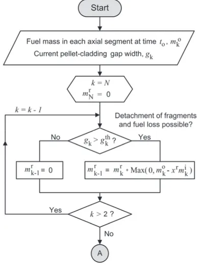
The second loop is run to update the fuel mass in each axial segment in case relo-cation actually occurs; see the flowchart in Fig. 3. From section 2.1.1, we recall that collapse of the fuel pellet column that triggers subsequent axial fuel reloca-tion takes place only if i
k M
k m
m , i.e. if the initial fuel mass in the segment is less than the mass that can be accommodated by the distending cladding, considering that the disorderly stacked fuel fragments have a packing fraction k 1. As indi-cated in Fig. 3, there are also two additional constraints on the fuel relocation; it may occur only in the downward direction, and only if detached fuel fragments are available in axial segments at higher elevations. These conditions can mathe-matically be expressed by
9
k j o j r k k j j k k j o j m m m m m 1 1 1 1 . (5)The centre part of eq. (5) defines the total fuel mass up to the k:th axial segment at end of the current time step. The left-hand condition ensures downward reloca-tion, since it states that the total fuel mass in all axial segments up to the k:th seg-ment should not decrease during the considered time step. The right-hand condi-tion in eq. (5) states that the mass increase for the k:th segment during the time step is limited by the availability of detached fuel fragments in segments at higher elevations; m is the available fuel mass, evaluated during the first loop of the kr
algorithm.
Fig. 2: First loop over axial segments is run to determine the fuel mass that may relocate (fall down) into each segment, mkr.
Equation (5) can be cast into ) , ( Max kL M k k m m m or Max( , kL) i k k m m m , (6) ) , ( Min Uk M k k m m m or Min( , Uk ) i k k m m m , (7) SSM 2015:37
10
where M k
m is the trial value for m , defined by eq. (3), and the lower and upper k constraint values are given by
1 1 1 k j j k j o j L k m m m , (8)
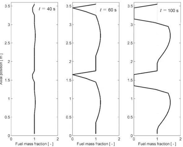
1 1 1 k j j k j o j r k U k m m m m . (9)It should be remarked that the left-hand-side branch of the condition inside the loop in Fig. 3 handles the case with relocation of fuel that maintains its original pellet-like geometry, without disordering the fuel fragments. This kind of reloca-tion typically occurs in axial segments with moderate cladding distension above the ballooned region of the fuel rod. It occurs without changing the fuel mass for most axial segments, but an empty axial space is created between the part of the fuel column that is free to relocate downward (g > gth) and the part that is stuck by
contact with the cladding tube (g < gth). The behaviour is illustrated in section 3 of
the report.
Fig. 3: Second loop over axial segments. The constraints on the updated fuel mass,
k
m , enforced by the min/max conditions, are explained in the text.
11
It should be remarked that the relocation model provides an upper bound for the fuel mass that may be ejected into the coolant, should the cladding fail in the k:th axial segment. Assuming that the ejected fuel will include all fuel above the clad-ding breach that is free to move downward (m ) and all fuel within the k:th seg-kr ment, except for the aforementioned residual part xrmik, the upper bound for the ejected fuel mass is mkr Max(0,mko xrmki). Possible improvements of this up-per bound estimate are discussed in section 5.3.
2.2. Fuel fragmentation and pulverization
As mentioned in section 2.1, the key parameters and g in our relocation model th are assumed to depend on the state of fragmentation for the fuel pellet column. The applied methodology and the correlations used for quantifying these depend-encies are described below. Henceforth, we discriminate between fuel fragmenta-tion and fuel pulverizafragmenta-tion: Fuel fragmentafragmenta-tion inevitably occurs under normal reactor operation by thermally induced stresses in the fuel pellets, and the frag-ments formed are usually fairly large (> 1 mm). Fuel pulverization, on the other hand, occurs when high burnup fuel is transiently overheated. As the name indi-cates, the phenomenon produces a “pulver”, consisting of very fine (< 0.2 mm) fuel fragments. The two mechanisms are treated in subsections 2.2.1 and 2.2.2, where empirically based submodels for estimating the state of fuel fragmentation and pulverization from information on the operating life of the fuel are presented. The experimental studies and data, on which these empirical models are based, are presented in Appendix A. Subsections 2.2.3 and 2.2.4 deal with the calculation of the key model parameters and g from the estimated state of fuel fragmenta-th tion and pulverization. A review of the fuel fragmentation and pulverization phe-nomena with emphasis on their importance for fuel rod behaviour under loss-of-coolant accidents can be found in [12].
2.2.1. Fuel fragmentation
Fuel fragmentation is a fairly well known phenomenon, since it occurs during normal operation of oxide nuclear fuel. As explained in Appendix A, the fragmen-tation is caused mainly by internal stresses induced by the strong radial tempera-ture gradient in the fuel pellets. Ceramographic investigations [18] of irradiated fuel show that the fragments are inversely correlated in size to the peak linear heat generation rate (LHGR) experienced by the fuel during its reactor life time. The fuel fragment size is also known to decrease slightly with increasing burnup. Empirical correlations have been proposed in the literature, by which the crack density and/or fuel fragment size can be estimated from fuel pellet average burnup and peak LHGR; these correlations are reviewed in Appendix A.
12
Fuel fragments formed by thermally induced stresses during normal reactor opera-tion are fairly large; as shown in Appendix A, reported fragment sizes typically range from about 2 to 4 mm. As revealed by ceramographic investigations of irra-diated fuel directly before and after LOCA testing, there is very little additional cracking of the fuel during a typical LOCA for fuel pellets with an average burnup below about 60 MWd(kgU)-1. In fuel pellets with higher burnup, fuel
pulveriza-tion may occur; see secpulveriza-tion 2.2.2.
Based on the aforementioned observations, it is assumed in our model that the mm-sized fragments formed during normal reactor operation do not crack further during LOCA, unless the fuel burnup and temperature are high enough for fuel pulverization to occur. Moreover, for ease of modelling, the mm-sized fragments are considered to have the shape of right triangular prisms, where the height and all base side lengths are equal. This approximation is based on the results from ceramographic investigations, see Appendix A. From these results, it also follows that the characteristic side length of the prismatic fragments can be estimated from
) , 1 ( Min f FP f D n l , (10)
where DFPis the fuel pellet diameter and n is the number of radial cracks inter-f secting the pellet outer surface at a particular axial cross section. Here, n is cal-f culated from the pellet average burnup and the peak LHGR experienced by the fuel during its lifetime through the empirical correlation by Walton and Matheson [19], presented in Appendix A. The characteristic fragment size defined by eq. (10) is plotted for a typical 17×17 pressurized water reactor (PWR) fuel rod with
FP
D = 8.26 mm in Fig. 4.
Fig. 4: Characteristic fuel fragment size, lf, versus fuel burnup (legend) and maximum LHGR experienced by the fuel during its lifetime. Here, lfis calculated from
eq. (10), assuming a fuel pellet diameter of 8.26 mm.
13
As shown by Fig. 4, the calculated characteristic fragment size is 2–3 mm for typ-ical values of maximum LHGR (25–40 kWm-1) experienced by the fuel in com-mercial power reactors. This fragment size is well in line with those reported from ceramographic investigations; see Appendix A.
2.2.2. Fuel pulverization
The mechanisms responsible for pulverization of high burnup fuel are poorly un-derstood. The prevailing hypothesis is that the pulverization occurs by cracking initiated at overpressurized bubbles and pores that contain gaseous fission prod-ucts [20-22]. Hence, a critical overpressure in the pores must be reached for pul-verization to occur. This means that the material must be sufficiently overheated with regard to its steady-state irradiation temperature. Moreover, the overheating needs to be fairly fast to preclude stress relaxation by creep or re-solution of gas into the material surrounding the pores. According to a recent review [20-22], experiments show that the average size of the fuel fragments formed by pulveriza-tion decreases with increasing heating rate and maximum temperature reached. The hypothesis also implies that cracking can be suppressed by a confining hydro-static pressure, imposed by pellet-cladding mechanical interaction. This suppres-sion has been experimentally confirmed [20-22].
Appendix A summarizes available studies and data on the pulverization phenom-enon. Based on the results of these studies, we make the following empirically based assumptions in our model:
Fuel pulverization may occur only in those parts of the fuel pellets that have a local burnup above 70 MWd(kgU)-1. This threshold burnup is similar to the local burnup at which a porous high burnup structure (HBS) forms at the pel-let periphery, the so called rim zone microstructure [23, 24]. However, in our model, the pulverization is not confined to the re-structured material in the pellet rim.
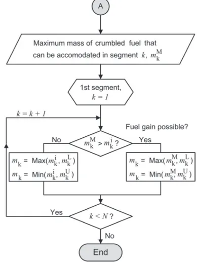
Pulverization occurs in the high burnup material only if the local temperature exceeds a critical threshold and the pellet-cladding contact pressure is lower than 50 MPa. The applied temperature threshold is the one recently proposed in [20-22], based on available data. It is shown Fig. 5.
The fuel fragments formed by pulverization are octahedral in shape and have equal size. This size, l , is a model parameter. From the analysis presented in p
section 2.2.3, l is set to 100 µm. p
When applying the temperature threshold defined in Fig. 5, the local fuel tempera-ture and burnup is calculated by the host computer program, in our case an ex-tended version of FRAPTRAN-1.5.1 The amount of pulverized fuel is thus
1 The local burnup is in fact calculated in a pre-processing step by the FRAPCON-3.5
program [25], using the TUBRNP micro burnup model [26]. FRAPCON is used for gener-ating burnup dependent initial conditions for transient analyses with FRAPTRAN.
14
lated by comparing the local state of the fuel with the burnup dependent tempera-ture threshold in Fig. 5. For illustration, we have calculated the volume fraction of material that may pulverize versus the pellet radial average burnup for a typical fuel design and operating history. The calculations, which are thoroughly de-scribed in [27], were done for a 15×15 type PWR fuel rod. The results are shown in Fig. 6. The step-like nature of the calculated curves reflects the radial discreti-zation of the fuel pellet used in FRAPCON; the pellet is here divided into 25 an-nuli.
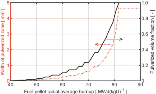
In conclusion, the calculated results in Fig. 6 show that the volume fraction of fuel that may pulverize start to increase rapidly as the fuel pellet radial average burnup exceeds about 65 MWd(kgU)-1. Above 82 MWd(kgU)-1, the entire pellet may
pulverize if transiently overheated, since the local burnup then exceeds 70 MWd(kgU)-1 everywhere. The calculated volume fraction of pulverized fuel
pre-sented in Fig. 6 is in fair agreement with unpublished data from out-of-reactor heating tests on high burnup UO2 fuel that have recently been carried out in
Studsvik, Sweden.
Fig. 5: Temperature threshold for pulverization in comparison with experimental data. The threshold is empirically based [20-22]; see Appendix A. The two breakpoints
in terms of fuel local burnup and temperature are (70 MWd(kgU)-1, 1200 K)
and (94 MWd(kgU)-1, 910 K).
15
Fig. 6: Calculated width of pulverized zone (i.e. a zone with local burnup > 70 MWd/kgU) and the corresponding volume fraction of pulverized material versus fuel pellet
radial average burnup. The calculations pertain to a 15×15 type PWR fuel rod with a pellet diameter of 9.30 mm; see [27] for further details.
2.2.3. Packing fraction of crumbled fuel
The packing fraction, , of crumbled fuel in ballooned segments of the fuel rod depends on the shape and size distributions of the disorderly stacked fragments; introductions to the subject of particle packing are provided in [28, 29]. For uni-formly shaped and sized particles, it is well-established that the packing fraction generally increases with increasing sphericity of the fragments. Sphericity, , is mathematically defined as the ratio of the surface areas between a sphere and a particle of the same volume as the sphere. Hence,
p p A V 2/3 3 / 1 ) 6 ( , (11)
where A and p V are the particle surface and volume. By definition, spheres have p = 1. The sphericity of other basic particle shapes is presented in Table 1.
For monosized particle beds, i.e. for cases where all particles have the same size and shape, the packing fractions for randomly packed beds range from 0.60 to 0.75 for the particles listed in Table 1. Higher packing fractions can be reached if particles with different sizes are mixed, since small particles may fill the voids between large particles. There are no simple theories or models that successfully describe the relationship between a general particle size distribution and packing fraction [30]. However, such models do exist for binary mixtures of particles, i.e. mixtures consisting of two types of monosized particles with well defined shapes.
16
These models are sufficient for our needs, since we consider two types of fuel fragments: prismatic fragments with a typical size of a few millimetres, and octa-hedral fragments that are a 1–2 orders of magnitude smaller. In the following, we will refer to properties of these two types of fragments by use of subscripts L and S (Large and Small).
Table 1: Sphericity, , and equivalent packing diameter, Dp, for selected idealized particle shapes with volume Vp and area Ap.
Shape and dimension D p V p A p
Sphere with diameter s 1.000 s 0.5236s3 s2
Cube with side s 0.806 1.147s s3 6s2
Octahedron with side s 0.846 0.895s 0.4714s3 3.4641s2
Ideal cylinder, h=s 0.874 1.069s 0.7854s3 4.7124s2
Triangular prism, h=s 0.716 0.910s 0.4330s3 3.8660s2
A widely used relation for characterizing the packing fraction of binary particle mixtures is due to Westman [31], who considered a mixture of large (L) and small (S) particles with known mass fractions x and L xS 1xL, respectively.
The packing fractions of mono-component beds of the large and small particles are also assumed to be known and denoted L and S. The overall packing
frac-tion of the binary mixture, , can then be estimated from a simple relafrac-tion 1 2 2 2 Gab b a , (12) where
L L L S x a , (13)
L
S S L S L L S x x b 1 , (14) SSM 2015:3717
and G is a parameter that depends on the differences in particle shape and size between the two components of the mixture. This parameter can be fitted empiri-cally to a specific binary mixture, but some general expressions for estimating G based on the particle characteristics also exist in the literature [32, 33]. Here, we will calculate G from
824 . 0 / , 1 824 . 0 / , ) / ( 738 . 0 1.566 L p S p L p S p L p S p D D D D D D G , (15)
where DSp and DpL are the equivalent packing diameters of the small and large particles. The equivalent packing diameter is calculated from the particle volume
p
V and sphericity through
3 / 1 2 8660 . 1 5684 . 4 9431 . 3 p p V D . (16)
Equations (15) and (16) have been proposed by Yu et al, based on measurements of packing fractions for a large variety of binary mixtures [32]. Calculated values for the equivalent packing diameter of the various particles are given in Table 1. For our applications, G ranges from about 40 to 150, depending mainly on the relative difference in fragment size between the large and small fragment class. In order to apply eqs. (11)-(16) to the putative binary mixture of fuel fragments in ballooned parts of the fuel rod, we need to define the packing fractions of mono-component beds of large and small fuel fragments, i.e. the parameters L and S. For the packing fraction of large fragments, we rely on the measured data present-ed by Siefken for eight fuel rods testpresent-ed in the PBF [7]. The investigatpresent-ed rods had burnups up to 16.6 MWd(kgU)-1. Gamma scanning and photomicrography of
se-lected cross sections were used to determine the packing fraction of the collapsed fuel pellet column in ballooned parts of the test rods after LOCA testing. The measured packing fractions ranged from 0.62 to 0.79, with an average value of 0.69. This value is in line with those reported for particles of similar shape in monosized particle beds [29].
The packing fraction of small fragments formed by pulverization of high burnup fuel must be estimated, since measured data are unavailable. From Appendix A, we recall that the fuel pulverization mechanism is reported to produce fragments over a fairly wide size range; observed fragment sizes typically range from 20 to 200 µm. For this reason, it is likely that the fragment packing fraction is higher than obtained for monosized particle beds. Pending reliable data, we assume a packing fraction of 0.72 for the small fragments resulting from pulverization. Hence, the packing fractions entering eqs. (13) and (14) are L 0.69 and
72 . 0
S
. The mass fraction of small fuel fragments, x , is calculated by apply-S ing the fuel pulverization threshold in section 2.2.2, and parameter G is calculated from the size difference between large and small fragments. The typical size of
18
large fragments is calculated through eq. (10), whereas the size of small fragments from the pulverized part of the fuel pellets is treated as a free parameter.
Fig. 7 shows the calculated fuel fragment packing fraction as a function of the small fragment mass fraction, x , in the mixture. All calculations were made for a S
fixed size of 2.0 mm for the large fragments, whereas five different sizes were assumed for the small fragments. According to the calculations presented in Fig. 7, the binary mixture reaches a maximum packing fraction when the mass fraction of small fragments is between 0.25 and 0.35. The peak value, as well as the loca-tion of the peak, depends on the difference in fragment size between the large and small fragment class. For the small fragment class that results from fuel pulveriza-tion, we note that very small fragments are able to fill the gaps between the mm-sized fuel pieces more efficiently than larger fragments. A theoretical maximum for can be calculated by letting the small fragment size tend to zero [29]. This asymptotic maximum is L S LS, or 0.9132 with our choice of
L
and S (0.69 and 0.72). From Fig. 7, it is clear that the calculated peak for the
case with 25 µm-size fragments is close to this theoretical maximum.
Fig. 7: Fuel fragment packing fraction versus relative amount of small fragments from pulverized high burnup fuel, calculated through eqs. (11)-(16). The large fragment
size was assumed to be 2.0 mm throughout the calculations.
It is also clear from Fig. 7 that the calculated packing fraction of the fragment mixture is not so sensitive to the assumed size of the small fragments produced by the pulverization mechanism: The peak packing fraction changes merely from 0.90 to 0.85 as the fragment size is increased from 25 to 200 µm. This fairly mod-erate change suggests that our relocation model will not be particularly sensitive to the assumed fragment size. Henceforth, we assume that the small fragments produced by pulverization of high burnup fuel are 100 µm in size.
19
By combining the calculated curve for the 100 µm fragment size in Fig. 7 with eq. (4), we may calculate the cladding threshold strain for collapse of the fuel pellet column into a crumbled state versus the relative amount of small fuel fragments. The results, which are presented in Fig. 8, show that the threshold strain decreases rapidly as the mass fraction of small fragments increases from zero to about 30 %, and then increases again. By combining the results put forth in Fig. 8 with those in Fig. 6, we may conclude that fuel with a pellet radial average burnup of about 72 MWd(kgU)-1, which is estimated to contain about 30 weight percent small frag-ments, would be particularly sensitive to axial relocation. We note that this hap-pens to be close to the burnup of rodlets 12 and 13 in the Halden IFA-650 series of in-reactor LOCA tests. Post-irradiation examinations give clear evidence of axial fuel relocation in both these BWR fuel rodlets [34].
Fig. 8: Cladding hoop logarithmic threshold strain for fuel pellet column collapse and onset of axial fuel relocation versus relative amount of small fuel fragments.
Here, the assumed size of large and small fragments in the binary mixture is 2.0 and 0.1 mm, respectively.
It may be interesting to compare the calculated threshold in Fig. 8 with threshold strains for axial relocation reported from experiments: Siefken [7] evaluated eighteen in-reactor LOCA tests done in the PBF reactor, USA, and Forschungs-reactor 2 (FR2), Germany. The evaluated test rods had burnups in the range of 0 to 35 MWd(kgU)-1, which means that small fuel fragments formed by pulveriza-tion did not exist [12]. Siefken concluded that no axial relocapulveriza-tion of fuel occurred in these rods for cladding hoop strains less than 17 %. This value is in very good agreement with our calculated threshold for a case without small-size fuel frag-ments. Later, Raynaud [12] reported a threshold cladding strain of 13–17 % for two Halden IFA-650 test rodlets with burnups of 56 and 61 MWd(kgU)-1. From Fig. 6, we expect the mass fraction of small fragments from pulverized fuel to be 0.05–0.10 for this burnup range, and from Fig. 8, we expect the corresponding
20
threshold strain to be 13–17 %. Hence, the calculated results are in perfect agree-ment with the observed strain thresholds. Moreover, the calculated trend of a de-creasing threshold strain with burnup over this range also agrees with the observa-tions [12].
Finally, it should be remarked that much higher threshold strains for fuel column collapse and axial relocation have been reported from out-of-reactor tests, carried out in the 1980s by the United Kingdom Atomic Energy Authority (UKAEA) on rodlets sampled from irradiated commercial PWR fuel rods [35, 36]. Internally pressurized samples with lengths from 450 to 800 mm were electrically heated to temperatures around 800 °C until the cladding ballooned. In some of the tests, X-ray radioscopy was used to monitor the deformation of the fuel pellet column in real time during the ballooning. Vibrations or end-loading of the fuel pellet col-umn were applied during some tests to simulate the in-reactor conditions expected during the reflood phase of the LOCA. Unfortunately, detailed information on these tests seems to be unavailable in public libraries and archives, but it is report-ed that, in general, the fuel pellet column did not collapse axially into the balloon until a cladding hoop strain of about 50 % was reached [36]. For lower strains, the fuel pellet column retained points in contact with the cladding by adopting a spiral configuration. Moreover, neither end-loading nor vibrations significantly affected the behaviour of the fuel pellet column [36].
2.2.4. Threshold for fuel fragment detachment
As described in section 2.1.1, our relocation model makes use of a threshold for the pellet-cladding gap size, gth, which defines the minimum space needed for fuel
fragments to detach from their original close-packed configuration and relocate downwards. This threshold gap size must be settled based on results of post-test examinations. To this end, we consider six fuel rods that were subjected to LOCA simulation experiments in Studsvik, Sweden [11]. Following the simulated LOCA transient, bend tests were conducted on the rods to measure the mechanical strength of the ballooned and ruptured region. The two halves of each broken rod were then inverted and gently shaken, in order to dislodge any loose fuel frag-ments within the cladding tube. The “mobile” part of the fuel column fell out, whereas fuel fragments restricted from moving remained within the fuel cladding. By correlating the position of the emptied part of the fuel column with cladding diameter measurements, Raynaud [12] determined a threshold hoop strain for fuel mobility for each of the six test rods. With a few exceptions, the measured thresh-old strains were in the range from 3 to 6 %; the average value was 4.5 % [12]. No significant influence of fuel pellet burnup on the threshold strain could be deter-mined; two test rods had a burnup of about 60 MWd(kgU)-1 and an average
threshold strain of 5.4 %, the remaining four rods had burnups of about 78 MWd(kgU)-1 and an average threshold strain of 4.1 %.
21
From the results of these measurements, we set the threshold pellet-cladding gap size for pellet fragment detachment, gth, to 0.2 mm in our model. This gap size
corresponds to a cladding hoop strain of about 4.4–4.8 %, depending on the clad-ding tube dimensions. More experimental data, similar to those discussed above, are needed to determine whether gth depends on fuel burnup or any other
parame-ter. It should be remarked that the results presented above are consistent with ob-servations from post-test investigations of fuel rods in the Halden IFA-650 LOCA test series. From these investigations, it is reported that the local cladding hoop strain must exceed about 5 % to produce visible fuel cracking and to allow frag-ment separation and movefrag-ment [34].
2.3. Modifications to thermal calculations
The axial relocation of fuel fragments changes the axial distributions of stored heat and power along the fuel rod. This must be accounted for in calculations of the fuel rod temperature distribution. Moreover, when the fuel pellet column col-lapses and fuel fragments move radially outward in ballooned segments of the fuel rod, it is no longer justified to calculate the fuel radial temperature distribution based on the usual geometrical assumptions of a solid cylindrical fuel pellet sur-rounded by an annular gas-filled pellet-cladding gap [17]. When the balloon is filled with crumbled fuel from the collapsed fuel pellet column, the pellet-cladding gap is significantly reduced. At the same time, gas-filled voids open up between the disorderly stacked fuel fragments. As the volume fraction of gas is typically 20–30 %, the macroscopic thermal conductivity of the crumbled fuel in the balloon is much lower than that of solid fuel material. Consequently, the main results of fuel crumbling on the fuel radial temperature distribution are a lower fuel temperature close to the cladding surface (due to a reduced pellet-cladding gap) and a steeper radial temperature gradient (due to a low macroscopic thermal conductivity of the solid-gas mixture). Fuel fragment axial and radial relocation also changes the distribution and temperature of free volume gas within the fuel rod. In particular, some axial segments of the fuel rod may be partly or completely emptied of fuel, which necessitates a modified strategy for calculating the gas temperature in these segments.
The following subsections deal with the modifications made to the thermal calcu-lations in our version of FRAPTRAN-1.5. When introducing these modifications, several bugs and inconsistencies were found in the source code and algorithms used for fuel rod temperature calculations in the original version of FRAPTRAN-1.5 [37]. These errors are corrected in our extended version of FRAPTRAN-FRAPTRAN-1.5, and the general thermo-mechanical solution strategy is modified, such that the fuel rod deformations are fully accounted for in thermal analyses.
22
2.3.1. Radial heat conduction equation
The fuel temperature calculations are carried out in FRAPTRAN-1.5 by solving the radial heat conduction equation,
) , ( 1 r t q r T r r r t T cpf f f , (17)
in each axial segment of the fuel rod individually. Hence, axial symmetry is as-sumed, and any axial heat conduction in the fuel pellet column is neglected. In eq. (17), T is temperature, r is the radial coordinate, q denotes the volumetric heat source, and f ,f and c are the density, thermal conductivity and specific heat pf capacity of the fuel material. The thermal conductivity and specific heat capacity are calculated through correlations, considering the material composition, local fuel temperature and burnup. It is assumed that the fuel material is identical in all axial segments, but an axially varying gadolinia concentration may be modelled, and the existence of a central hole in part of the fuel pellet column can be consid-ered [17]. The volumetric heat source in the right-hand-side of eq. (17) is pre-scribed as input, and is allowed to differ from one axial segment to another. In FRAPTRAN-1.5, eq. (17) is solved by an implicit time stepping scheme, and a finite difference method is used for the spatial discretization [17, 38].
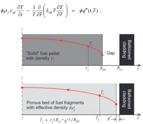
As explained in section 2.1.1, our model assumes that the fuel pellet stack col-lapses and the fuel fragments fall radially outward into the balloon when the clad-ding distension in the considered axial segment is large enough to accommodate the fragments in a disordered configuration, characterized by the packing fraction . Hence, there is a sudden transition to a new geometrical configuration. When this transition occurs in an axial segment, eq. (17) is modified such that it hence-forth represents an effective continuum material that consists of fuel fragments surrounded by stagnant gas. The term effective is used to communicate the con-cept that the material is assumed to be homogeneous on a macroscopic scale. This means that eq. (17) can still be applied, but the material properties must be modi-fied. The following changes are made to eq. (17) when the fuel pellet column col-lapses:
The radial positions of the nodes used for solving eq. (17) by the finite differ-ence technique are scaled, such that the collapsed pellet surface comes into partial contact with the cladding inner surface. In other words, the pellet-cladding gap is nearly closed; only a small residual gap, gr, remains, as
illus-trated in Fig. 9. The residual gap, which is a model parameter, accounts for the fact that the crumbled fuel is only in point wise contact with the cladding surface. Once the fuel pellet column has collapsed, the radial positions of the pellet nodes are continuously updated, such that the pellet-cladding radial gap is maintained at gr as the cladding distends further. It should be remarked that
Fig. 9 illustrates the instant of transition from a pellet-like configuration to a
23
porous bed; the radial temperature distribution will subsequently change as a result of the modified fuel geometry and thermal conductivity.
The fuel effective density is changed fromf to f, to reflect the transition from densely packed and ordered fuel fragments to a porous bed of frag-ments. Likewise, the volumetric heat source is changed from q to q , since it is proportional to the fuel density.
The fuel thermal conductivity is changed from f to eff, which is an effective
thermal conductivity for the crumbled fuel. The effective thermal conductivi-ty applied in our model depends on the thermal conductivities of the fuel fragments and the surrounding gas, and on the packing fraction of the fuel fragments. The model used for eff is described and validated against
experi-mental data in Appendix B.
The modified heat conduction equation thus reads
) ~ , ( ~ ~ ~ ~ 1 r t q r T r r r t T cpf eff f . (18)
Fig. 9: Assumed change of fuel geometry and effective fuel density following collapse of the fuel pellet column into a ballooned part of the cladding tube. Node positions in the fuel
are scaled, such that only a residual pellet-cladding gap, gr, remains after fuel crumbling.
It can be easily shown that the fuel mass and radial average enthalpy within the considered axial segment are unaffected by the modifications listed above at the very moment of transition. After the transition, however, the fuel mass within the segment may change by axial relocation, and the radial average enthalpy may change as a result of the modified radial temperature distribution. It should be remarked that eq. (18) is used also in axial segments that are fully or partly emp-tied of fuel (xr < < 1). However,
f
and the original radial positions of the pellet
24
nodes are maintained in axial segments where the fuel pellet column has not col-lapsed.
2.3.2. Heat transfer by axial fuel relocation
Our model for axial fuel relocation in section 2.1.2 solves the conservation equa-tions for fuel mass, but it does not solve the conservation equation for energy with regard to the axial direction. This simplification could have some impact on the calculated fuel temperatures, in case large axial gradients in fuel temperature exist along the part of the rod where fuel relocation occurs. To illustrate this issue, we consider the enthalpy per unit length of the fuel column, henceforth denoted H´. The conservation equation for this property can be written as
H uz
q Rcihgap Tgap z t H 2 , (19)where uz is the axial velocity of the relocating fuel fragments, q´ is the fuel linear
heat generation rate, hgap is the pellet-cladding gap heat transfer coefficient and
Tgap is the temperature drop across the gap. Consider now the k:th axial segment
of the fuel rod, which extends from z = z1 to z = z2. The rate of change for the
average fuel enthalpy, Hk, within this segment is obtained by integration of eq.
(19) over z
cik gap gap
k z z k H z u z H z u z L q R h T t d dH 2 ) ( ) ( ) ( ) ( 2 2 1 1 , (20)
where Lk = z2 - z1 is the length of the axial segment. The axial velocity of the fuel
at the upper and lower boundaries of the segment, uz(z2) and uz(z1), can be
ob-tained from the axial relocation algorithm in section 2.1.2, but the fuel enthalpy per unit length at these positions is not calculated. For this reason, we introduce the approximation H(z1)H(z2)Hk in eq. (20), which results in
z z
k
cik gap gap
k k H u z u z L q R h T t d dH 2 ) ( ) ( 2 1 . (21)
This equation is solved by our modified heat transfer model in FRAPTRAN. It accounts for changes in total fuel enthalpy in the k:th axial segment by accumu-lation, uz(z2) < uz(z1), or loss, uz(z2) > uz(z1), of fuel fragments. However, it
ne-glects that fuel fragments falling down into the considered segment may have dif-ferent temperature and specific enthalpy than fragments already in the segment and/or fragments exiting the segment at the bottom.2 Consequently, the
approxi-mation is justified as long as the axial fuel relocation occurs between segments with about the same fuel temperature and specific enthalpy. Cases with steep axial temperature gradients along those parts of the fuel rod that are affected by fuel relocation will be poorly reproduced by the model.
2 Compare with the complete conservation equation for enthalpy in eq. (20), from which it
is clear that Hk will change also when uz(z2) = uz(z1), if H´(z2) ≠ H´(z1).
![Fig. 5: Temperature threshold for pulverization in comparison with experimental data. The threshold is empirically based [20-22]; see Appendix A](https://thumb-eu.123doks.com/thumbv2/5dokorg/3340829.18560/26.892.140.669.528.840/temperature-threshold-pulverization-comparison-experimental-threshold-empirically-appendix.webp)