MASTER'S THESIS
Leveraging Ontology Technologies for
Data Modeling in Space Engineering
Mauro Aja Prado
2013
Master of Science (120 credits) Space Engineering - Space Master
Leveraging Ontology
Technologies for Data Modeling
in Space Engineering
Mauro Aja Prado
Department of Computer Science, Electrical and Space
Engineering
Lule˚
a University of Technology
Supervisors:
Harald Eisenmann, EADS Astrium Satellites
Jana Mendrok, Lule˚
a University of Technology
A thesis submitted in partial fulfilment for the degree of
Master of Science
A mis padres y hermano. Su amor, sacrificio y apoyo incondicional me han permitido descubrir el mundo. Sin ustedes nada de esto
Abstract
Systems Engineering has been a key interdisciplinary approach for the development of complex engineering projects for quite some time, and naturally, because of the wide range of disciplines involved in space programs it has been applied in this industry. Software technolo-gies have been assisting this approach with domain-specific modeling software. As a result, descriptive models of systems are possible (me-chanic, electric, etc.). There is a variety of possibilities to produce models and to model data. A natural evolution of Systems Engineer-ing: Model Based Systems Engineering, relies on the use of a central-ized system model to support diverse engineering activities through-out the life cycle of a project. Modeling languages such as UML and Ecore are popular for developing applications and models. However, other techniques such as ontologies are used in areas other than en-gineering to produce models of things. In this thesis, the properties of OWL ontologies are analysed and exploited for the development of data categories which are intended to describe discipline-specific properties of a system and hence, translate into benefits for engineer-ing tasks. In this thesis, a model of a spacecraft is proposed which makes use of different data categories and allows to assess ontology features such as reasoning and inference, disjoint axioms and multiple instantiation of classes in order to represent different system levels. Furthermore, the desired model is used in an Ecore based solution that adopted some ontology concepts in order to have a comparison to currently existing technologies. An analysis of implications, op-portunities and limitations is performed for both approaches and a recommendation for the future of data modeling is derived.
Acknowledgements
I would like to express my deepest gratitude to my supervisor in EADS As-trium, Harald Eisenmann. Also, I would like to thank Christian Hennig for all his support and patience while answering my many doubts and for assisting me throughout the development of this thesis. Special mention to Tobias Steinle for giving me such a warm welcome during the cold winter in Friedrichshafen and for giving me the opportunity to do my thesis in the company. This gratitude is extended to the Satellite FVI, Engineering Tools, Modeling and Simulation (ACE82) department of Astrium Satellites, Friedrichshafen, Germany.
At the Universit´e Toulouse III Paul Sabatier I would like to thank Professor Christophe Peymirat for all his support and orientation during the program. My gratitude too for Peter von Ballmoos and Domminique Toublanc. My gratitude is extended to H´el`ene Perea and to Maude Perier-Camby for all their support with administrative issues and for making easier my adaptation to Toulouse. At Lule˚a University of Technology I would like to express my gratitude to Victoria Barabash, Anette Sn¨allfot-Br¨andstr¨om and Maria Winneb¨ack for their continuous support throughout the SpaceMaster program. My gratitude to Jana Mendrok for her supervision of this thesis.
I would like to thank to all the amazing people I have met during these 2 years. All the SpaceMaster family, the French students from the M2PTSI in Toulouse, and all the interns in Friedrichshafen: the Italians, the Mexicans, the French, the Germans, and the rest. Your friendship has been vital for me and it will never be forgotten. Special mention goes to Tiago Rebelo, Ishan Basyal, Dries Agten and Bastian Hacker which, I have had the opportunity to spend more time with along this journey.
Last but not least, I would like to thank and express my most sincere gratitude to my parents and my brother. Your unconditional love and support have forged the person I am today. Thank you for being such amazing role models and inspiring people. Without you, nothing of this would have been possible.
Contents
Contents viii
List of Figures xi
List of Tables xiii
List of Abbreviations xiv
1 Introduction 1
1.1 Motivation . . . 1
1.2 Objectives . . . 3
1.3 Outline . . . 4
2 Systems Engineering and Model Based Systems Engineering 5 2.1 Systems Engineering . . . 5
2.2 Model Based Systems Engineering . . . 9
2.2.1 Data Modeling . . . 11
2.2.2 Data Categories . . . 12
2.2.2.1 Motivation . . . 12
2.2.2.2 Applications . . . 12
3 Approaches to Data Modeling 14 3.1 Traditional Modeling . . . 14
3.1.1 Traditional Approaches . . . 14
3.1.1.1 Excel . . . 14
CONTENTS
3.1.2 Properties of these approaches . . . 15
3.2 Model-Based . . . 17
3.2.1 Model-Based Approaches . . . 17
3.2.1.1 SysML . . . 17
3.2.1.2 Relational Databases . . . 18
3.2.2 Properties of These Approaches . . . 19
3.3 Ontologies . . . 20
3.3.1 Ontology Languages . . . 22
3.3.1.1 OWL . . . 22
3.3.2 Properties of OWL . . . 23
3.3.2.1 Reasoning & Inference . . . 23
3.3.2.2 Queries . . . 25
3.4 Enhanced Software Modeling Languages . . . 26
3.4.1 Ecore++ . . . 27
3.4.2 Motivation behind Ecore++ . . . 28
3.4.3 Properties of Ecore++ . . . 29
4 Specification of Research 30 4.1 Research objectives . . . 30
4.2 Method . . . 30
4.2.1 Sample Data . . . 31
4.2.2 Selection of Language and Tool . . . 31
4.2.2.1 OWL/Prot´eg´e . . . 31
4.2.2.2 Ecore-Based/SSDE . . . 32
4.2.3 Approach . . . 32
4.2.3.1 Modeling engineering data using both approaches 33 4.2.3.2 Pointing out the characteristics of the models . . 34
4.2.3.3 Deriving implications, limitations, and opportu-nities . . . 35
5 Description and Analysis of Research 36 5.1 OWL . . . 36
CONTENTS 5.1.2 Model characteristics . . . 38 5.1.3 Implications . . . 40 5.1.4 Limitations . . . 48 5.1.5 Opportunities . . . 49 5.2 Ecore-Based . . . 50 5.2.1 Model description . . . 50 5.2.2 Model characteristics . . . 57 5.2.3 Implications . . . 57 5.2.4 Limitations . . . 59 5.2.5 Opportunities . . . 60 6 Conclusions 61 6.1 Comparison of both approaches . . . 61
6.2 Recommendations for future data modeling . . . 63
6.3 Future work . . . 63
List of Figures
2.1 Systems life cycle processes by ISO/IEC 15288 [23]. . . 6
2.2 SE in context of overall project management [31]. . . 7
2.3 Typical example of a product tree [10]. . . 8
2.4 MOF Metadata Architecture [2]. . . 12
3.1 TM downlink baseline budget example. . . 15
3.2 PCDU technical model description example [28]. . . 16
3.3 SysML parametric diagram example [24]. . . 18
3.4 FDIR failure cases example. . . 19
3.5 Representation of the elements that conform an ontology [22]. . . 22
3.6 Model representation of a bowling league. . . 27
3.7 Key functions provided by the VSEE [15]. . . 28
4.1 Satellite Operation Modes vs. Mission Phases. . . 35
5.1 Component Aspect Visualization. . . 37
5.2 Discipline Aspect Visualization. . . 37
5.3 Engineering Aspect Visualization. . . 37
5.4 Mission Phases Aspect Visualization. . . 38
5.5 System Operations Aspect Visualization. . . 38
5.6 Element Ocurrence - MTQ-1. . . 39
5.7 System Operations - Calibration-A. . . 40
5.8 Rule Example - If a component has mass then it should be consid-ered as a mechanical component. . . 41
LIST OF FIGURES
5.10 Rule Example - Drools inferred instances. . . 42
5.11 Rule Example - Conversion from kg to pounds. . . 43
5.12 Before and After the application of the SQWRL rule. . . 44
5.13 Query 1 - Mass of all the components that belong to CGPS. . . . 45
5.14 Query 1 - Result. . . 45
5.15 Query 2 - AOCS components that are on during launch. . . 46
5.16 Query 2 - Result. . . 46
5.17 Query 1 - Result exported to Excel. . . 47
5.18 Spacecraft Subsystem - Component Aspect. . . 51
5.19 Spacecraft Subsystem hierarchical tree representation. . . 51
5.20 AOCS - Component Aspect. . . 52
5.21 AOCS - Engineering Aspect. . . 53
5.22 Mission Phases. . . 54
5.23 System Operations. . . 55
5.24 System Operations and Mission Phases. . . 56
5.25 Calibration Mode description. . . 56
5.26 Elements defined under the AOCS subsystem. . . 58
List of Tables
2.1 Typical space project life cycle . . . 7 3.1 Classification of elements in the example of Figure 3.5. . . 22
List of Abbreviations
AOCS Attitude and Orbital Control System
CATIA Computer Aided Three-dimensional Interactive Application
CDM Conceptual Data Model
CGPS Cold Gas Propulsion System
CWA Closed-World Assumption
DIG DL Implementation Group
DL Description Logics
DSIG Domain Special Interest Group
ECSS European Cooperation for Space Standardization EMF Eclipse Modeling Framework
EPS Electrical Power System
ESA European Space Agency
FDIR Failure, Detection, Isolation and Recovery INCOSE International Council on Systems Engineering LEOP Launch and Early Orbit Phase
LIST OF ABBREVIATIONS
MOF Meta-Object Facility
MTQ Magnetic Torquer
NASA National Aeronautics and Space Administration
OBC On-Board Computer
OBS On-Board Software
OMG Object Management Group
OWA Open-World Assumption
OWL Web Ontology Language
PCDU Power Control and Distribution Unit RDF Resource Description Framework
RDF-S RDF Schema
SE Systems Engineering
SQWRL Semantic Query Enhanced Web Rule Language SSDE Space Systems Design Editor
SSRDB Space System Reference Database SSVT Space Systems Visualization Tool SysML Systems Modeling Language UML Unified Modeling Language VSD Virtual Spacecraft Design
VSEE Virtual Spacecraft Engineering Environment
W3C World-Wide Web Consortium
XMI XML Metadata Interchange
Chapter 1
Introduction
“A systems engineer is a problem stater” - A. Wayne Wymore
1.1
Motivation
Space programs require a great deal of expertise of several different areas such as: mechanical engineering, electrical engineering, software engineering, etc. Eventu-ally all these areas have to interact in a certain point and be integrated together. In order to successfully address these challenges, such complex projects are tack-led using the Systems Engineering approach. Different types of industries benefit from this type of practice such as: space, automotive, aeronautical, etc.
Traditionally, systems engineering has been supported by a document-based ap-proach, in which, with the elaboration of documents it is possible to describe systems in the required detail. However, several issues have been identified with a document-based approach. Information sharing is one example, as it is difficult and prone to error. Other example is that reuse of engineering artifacts such as systems requirements require significant effort and time. And so, a natural evolution of this practice is to make use of computer generated models for the support of diverse engineering activities. This approach is called Model Based Engineering. Enhancing this approach by including a centralized system model
1. Introduction
is referred as Model Based Systems Engineering.
Several types of models exist and have been used for creating proper character-izations of a system, however these models tend to be discipline specific and of really different natures, such as mechanical models or electrical models. Within the development of a space project, life cycle phases and different system levels are clearly defined according to several standards. The Model Based Systems Engineering intends to support activities that begin from the conceptual design phase all the way to integration and final phase with the use of a centralized system model. These activities include definition of system requirements, design, analysis, verification and validation.
One way to enable the MBSE approach is to make available a Conceptual Data Model (CDM) that serves as a central structure for all involved domains and their tools. This CDM can be described with a variety of approaches. Currently several techniques are used for modeling data: SysML, EMF Ecore and the most used, UML. These techniques present several advantages and of course disadvantages. A different technique is modeling engineering data with ontologies, in particular with the Web Ontology Language commonly known as OWL.
OWL ontologies rely on Description Logics and thus, they are based on seman-tically strong principles. By building on a sound semantic substructure, OWL offers a variety of functionality such as disjoint axioms, inference and reason-ing. Furthermore, the included set theory concept is able to describe knowledge more precisely than is possible with data modeling language that do not focus on knowledge representation. The application of ontologies is further analysed and how some desired properties provided by them can be applied to modeling techniques such as Ecore in order to extended its functionality.
1. Introduction
1.2
Objectives
In this thesis, different data modeling techniques that allow a fine-grained, mod-ular organization of engineering data are analysed and compared in detail. In order to achieve this, the main objectives are:
• Identification of unique properties of OWL ontologies that can be useful for data modeling.
• Modeling the same engineering data set with an Ecore-based solution that pragmatically adopted a couple of ontology concepts, and with OWL on-tologies in order to get a clear, substantiated picture for the comparison. • Identification of implications and opportunities that arise when modeling
with each of those language groups.
• Derivation of a recommendation for the future data modeling of engineering data categories.
Consequently, the implications and opportunities that arise when modeling with each of those language groups should be analysed. For example:
• The ontology-based approach might offer more expressivity through in-clusion/exclusion constructs, but might thus require runtime consistency checking in the form of reasoning.
• The ontology-based approach might offer the opportunity to provide inter-esting functionality in the form of inference on data model and user model level.
1. Introduction
1.3
Outline
This chapter states the motivation for conducting this work as well as the objec-tives of this research.
The second chapter provides a a general analysis of the concepts of Systems En-gineering and Model Based Systems EnEn-gineering. These concepts are explained making reference to international standards and their application in space engi-neering. Furthermore it is explained the concept of Data Modeling and its role in the current and future application of European space programs.
The third chapter gives a detailed description about some Data Modeling ap-proaches and provides the theoretical background for this thesis. First, the tradi-tional modeling approaches are introduced and discussed, later the model based approaches and last, the most significant approaches for this thesis: OWL on-tologies and the enhanced software modeling languages.
The fourth chapter provides the specification of research. In other words, it specifies a description of the proposed model that was built using the selected approaches. The necessary steps for conducting this work: Modeling data, se-lection of language and tool, the identification of implications, limitations and opportunities are clearly explained.
The fifth chapter is perhaps the most significant of this thesis since it describes the models that were elaborated using the selected approaches. Description, charac-teristics, implications, limitations and opportunities are deeply detailed for each model.
The last chapter, which is the conclusion addresses a summary and comparison of the selected modeling approaches, recommendations for future data category modeling and the future work that can be done in order to have a broader un-derstanding of data modeling for space engineering.
Chapter 2
Systems Engineering and Model
Based Systems Engineering
2.1
Systems Engineering
Systems Engineering (SE) refers to the practice of approaching complex engineer-ing problems from a multidisciplinary point of view in order to develop solutions which satisfy project and stakeholders needs and minimize risks for a successful project development [17]. SE has been largely promoted by the International Council on Systems Engineering (INCOSE). INCOSE introduces a more com-plete definition on SE [23]:
Systems Engineering is an interdisciplinary approach and means to enable the realization of successful systems. It focuses on defining customer needs and required functionality early in the development cycle, documenting requirements, then proceeding with design syn-thesis and system validation while considering the complete problem.
SE has been widely used in the space industry due to the complexity of the projects and advantages offered by this practice.
2. Systems Engineering and Model Based Systems Engineering
Management and technical processes must be applied together in order to achieve functionality, assure communication between developers and users, and have a re-duction of costs. Consistent with the ISO/IEC 15288 standard [1], there are 4 main process groups during the life cycle of the activities of SE which are sup-ported by INCOSE and are illustrated in Figure 2.1: technical, project, enterprise and agreement processes.
Figure 2.1: Systems life cycle processes by ISO/IEC 15288 [23].
A different but similar approach by the National Aeronautics and Space Adminis-tration (NASA) on their handbook for SE [31] divides these processes in: system design, product realisation and technical management processes, illustrated in Figure 2.2. Nevertheless, the objectives are the same.
In the European space programs the main reference for SE are the standards set by the European Cooperation for Space Standardization (ECSS) [11]. For prac-tical purposes in this thesis, these standards are taken as reference.
2. Systems Engineering and Model Based Systems Engineering
Figure 2.2: SE in context of overall project management [31].
Space projects comprise inter-disciplinary aspects and it is necessary to extend the SE approach during their whole life cycle. Table 2.1 illustrates the typical phases and main activities during their life cycle [10].
Table 2.1: Typical space project life cycle
Activities
Phases
Phase 0 Phase A Phase B Phase C Phase D Phase E Phase F
Mission/Function x x Requirements x x x Definition x x Verification x x x Production x x Utilization x Disposal x
In order to have a successful project development is important to have some breakdown which creates a common understanding between all the actors. These breakdowns allow to trace system level requirements into their required
imple-2. Systems Engineering and Model Based Systems Engineering
mentation, as well as the derived requirements from the next lower level [12]. The main breakdown structures according to the ECSS [10]:
• Function tree - System performances into functions.
• Specification tree - Hierarchical relationship of technical requirements. • Product tree - Breakdown into successive levels of detail (hardware and
software) that perform the functions specified in the function tree. An ex-ample of a product tree is depicted in Figure 2.3.
2. Systems Engineering and Model Based Systems Engineering
2.2
Model Based Systems Engineering
Traditionally SE has been handled from a document-based approach. Even though this approach can result in a pretty extensive description of a system, it has important limitations. Poor synchronization, difficulty to reuse system re-quirements, tight time constraints and cost are good examples of these limitations usually resulting in inefficiencies and quality issues. A model-based approach is the natural evolution of SE. It has started being used in the space industry, and is becoming more popular [13]. This model-based approach is called Model Based Systems Engineering (MBSE).
The use of models in engineering has been common using dedicated software for mechanic and electronic designs. Using models to represent graphical, mathemat-ical or logmathemat-ical concepts result in a proper characterisation of a system. It allows having a more complete integration of specifications and design of a system, and hence a better evaluation on the performance and limitations.
The official MBSE initiative is supported by INCOSE and the Object Manage-ment Group’s (OMG) SE Domain Special Interest Group (DSIG). The INCOSE SE 2020 vision defines MBSE as [33]:
The formalized application of modeling to support system require-ments, design, analysis, verification and validation activities begin-ning in the conceptual design phase and continuing throughout devel-opment and later life cycle phases. MBSE is part of a long-term trend toward model-centric approaches adopted by other engineering disci-plines, including mechanical, electrical and software. In particular, MBSE is expected to replace the document-centric approach that has been practised by systems engineers in the past and to influence the future practice of system engineering by being fully integrated into the definition of systems engineering processes.
2. Systems Engineering and Model Based Systems Engineering
MBSE enhances communication, precision, reuse of system requirements and al-lows costs reduction. MBSE begins in the conceptual design phase and is present during throughout development and later phases. The project documentation is generated from the model itself [17].
Referring to European space projects and taking as an example the typical life cycle from Table 2.1 in Section 2.1, in phase 0 and phase A the requirements are derived mostly by system budgets (mass, power, etc.). Phase B includes the use of domain-specific tools, in which elaborate tools exist for the support of the system level design (mechanical and electronic design). However, there are no tools dedicated for functional and operational aspects. It is desired to have inter-connection between different tools in order to have integration between different system levels during the project life cycle, but it turns out difficult and requires vast amount of time in order to share common data between them. Therefore a MBSE approach is desired [12].
Different types of models are used nowadays in the space industry, they are re-lated to each other because of their purpose and are important part of a project development [12]:
• Product instance models - Identify particular instances of the product to be delivered.
• Static or structure models - Capture the specification and definition of the system along the life cycle.
• Dynamic or behaviour models - Represent expected or actual behaviour of the system.
• Data (meta)models - Capture the structure of data to be used or required during the life cycle of computer applications in order to favour data ex-change.
• Modeling infrastructure models - Integration of the supporting tools in a modeling infrastructure.
2. Systems Engineering and Model Based Systems Engineering
• Process models - Capture and improve engineering processes workflows.
The aim for MBSE for European space programs as stated on INCOSE-INSIGHT (2009) [12] calls for making use of data models to address these challenges:
The way forward is to continue with, on the one hand, a top-down systems-engineering approach with conceptual, semantic, data models to help realize a true MBSE infrastructure, and on the other hand, a bottom-up software-and-simulator-engineering approach starting from the actually realized infrastructure.
Hence, the applied focus of this thesis is on the concept of data modeling for support on the MBSE approach.
It is important to clarify the difference between data models and user models. The Meta-Object Facility (MOF) standard [2], which is designed as a four lay-ered architecture, provides means to structure data. Figure 2.4 illustrates this pyramid with examples. The data model is present in the M1 layer and provides the modeling concepts which can be used to model the applications. The user model is present in the lowest layer M0 which is the one where the user interacts with the data model [21].
2.2.1
Data Modeling
As mentioned previously the aim is to apply MBSE in the form of data models, this means a special or particular focus on developing data oriented structures which from now on are referred as Data Categories. They allow to model from high level conceptual data to physical data models, and avoid inconsistencies in early stages. In Chapter 3 different approaches for data modeling are discussed focusing in ontologies and in enhanced software modeling approaches.
2. Systems Engineering and Model Based Systems Engineering
Figure 2.4: MOF Metadata Architecture [2].
2.2.2
Data Categories
Data categories are individual decompositions of a system that act as engineering databases. They are intended to aid to describe the design of the system from different perspectives, including the links that exist between them.
2.2.2.1 Motivation
An important objective for MBSE in space programs is the reuse of information. Every mission has completely different objectives and therefore spacecrafts are designed in a particular way for those purposes. They carry unique payload, they have different sizes and geometry and different needs. However, every single spacecraft has standard equipment that even though changes in specifications is pretty standard, a perfect example of this is the platform.
2.2.2.2 Applications
Data categories can be used for modeling a spacecraft from different perspectives and within interactions between different domains. This results quite helpful
2. Systems Engineering and Model Based Systems Engineering
when having to deal with complex systems. Examples of how this data categories can be used to model [13]:
• Requirements data. • Functional designs. • Operational designs. • Physical designs. • Verification data.
• Assembly, integration and test data.
These data categories define processes that are quite standard in the elaboration of a space program.
Chapter 3
Approaches to Data Modeling
3.1
Traditional Modeling
3.1.1
Traditional Approaches
As mentioned in the previous chapter, the current aim for SE and MBSE in space projects is to rely in the use of data models. It is important to understand the traditional approaches used for creating data categories and thus data models. It is paramount to know these approaches in order to identify their strengths and limitations against other approaches and to understand the natural evolution to-wards other approaches. The focus of this thesis is in ontologies as source of knowledge and enhanced modeling software from now on referred as Ecore++.
3.1.1.1 Excel
Microsoft Excel is well known by almost any regular computer user. Excel is a spreadsheet application which enables to store data and represent data in rows and columns. It allows numerical calculations and creation of plots to display the information, among other characteristics [7].
A perfect example of use of Excel in space projects is to calculate and represent telemetry or power budgets. Figure 3.1 illustrates and example of the downlink
3. Approaches to Data Modeling
telemetry baseline budget.
Figure 3.1: TM downlink baseline budget example.
3.1.1.2 Visio
Microsot Visio is an application for elaborating diagrams to simplify complex in-formation. It is possible to create block diagrams, organization charts, flowcharts, cross functional and simple workflows, schedule and timelines [8]. Figure 3.2 il-lustrates how Visio is used for describing a technical model of a Power Control and Distribution Unit (PCDU).
3.1.2
Properties of these approaches
These tools are relatively easy to use and have wide distribution. This make them extremely popular and ensures compatibility within organizations and
individu-3. Approaches to Data Modeling
Figure 3.2: PCDU technical model description example [28].
als. The vast majority of domain-specific engineers involved in a space project have used these tools in several occasions and therefore are common and do not require training for learning how to use them.
They allow high levels of descriptivity because of the use of natural language (i.e English), allow filter of information on different levels and querying is possible in order to find what is needed within their applications.
The use of these tools in space engineering has been predominantly in require-ments engineering for passing the information between different system levels and or actors along the project life cycle. However the use of these approaches is gen-erally tedious, requires large amount of time and the reuse of the information requires some effort.
Even though requirements are an important part of a project, it would be diffi-cult to think how to model other important aspects of a space project such as operational and functional aspects in which there are quite some dependencies and actors involved.
3. Approaches to Data Modeling
3.2
Model-Based
3.2.1
Model-Based Approaches
Model-based approaches represent an important part of data modeling in space engineering. This section is intended to give an overview of these approaches. 3.2.1.1 SysML
The Systems Modeling Language (SysML) is an extension of the Unified Mod-eling Language (UML). The former designed for SE applications and the later for software development. SysML is a general modeling language for specifying, analysing, designing and verifying complex systems [35].
SysML is structured into nine diagram types from which they are categorized in three different groups: requirement, behaviour and structure [17].
Requirement: Text-based requirements and their relationship with other require-ments.
Behaviour:
• Activity - Behaviour based on availability of inputs, outputs and control. • Sequence - Behaviour in terms of a sequence of messages between parts. • State machine - Behaviour of an entity in terms of its transitions between
states triggered by events.
• Use case - Functionality on how a system is used by external entities to accomplish goals.
Structure:
• Block definition - Structural elements called blocks, and their composition and classification.
3. Approaches to Data Modeling
• Internal block - Represents interconnection and interfaces between the parts of a block.
• Parametric - Constraints on property values, used to support engineering analysis.
• Package - Organization of a model in terms of packages that contain model elements.
Figure 3.3: SysML parametric diagram example [24].
Figure 3.3 illustrates a SysML parametric diagram. 3.2.1.2 Relational Databases
The Relational data bases concept has its origins in a research by Eduard Codd, in which he established the concept of the relational model and 12 rules for cre-ating a relational database [4]. Relational databases are databases composed of
3. Approaches to Data Modeling
a set of tables of data items, which is the most basic component. The rows of the table are called records and the columns are called fields or attributes. The main objective of the relational databases is to capture data in a simple way which can be understandable from both the designer and the user.
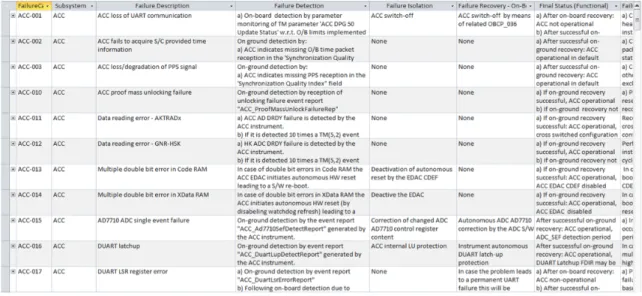
Microsoft Access is a perfect example of a relational database, although it has similar uses to Excel although it is not a spreadsheet but a database application. A big difference is that the main function of Access is the creation and manage-ment of complex and large databases in which the information is stored into data tables [6].
Access can be used to organize and store Failure, Detection, Isolation and Re-covery (FDIR) processes as illustrated in Figure 3.4.
Figure 3.4: FDIR failure cases example.
3.2.2
Properties of These Approaches
The use of a model-based approach allows to model more aspects than the tra-ditional approaches, it provides a more organized and standardized way of how
3. Approaches to Data Modeling
to structure the data to be modeled and a particular language for doing this. However, some level of descriptivity of the systems may be diminished.
SysML as a graphical modeling language helps to specify systems by defining its components so that they can be designed using other domain-specific software. This representation of systems and components includes: structural composition, behaviour, constraints and requirements, among many other possibilities [17].
Furthermore, is desired to organise and relate different levels of design. This implies that every element that could affect an analysis is present, identified and consistently related to other elements [26].
3.3
Ontologies
The use of ontologies in space engineering has been quite recent [25]. Ontologies act as a source of knowledge in which interesting features allow data modeling due to unique characteristics of this approach.
Currently many definitions of the concept of ontology exist by different authors. However, probably the most known or most widely used is the short and concise definition by Thomas Gruber [18], which has been adopted by the working groups of the semantic web.
An ontology is an explicit specification of a conceptualization
In other words, the purpose of an ontology is to give a specific vocabulary of a do-main in particular, in order to provide a source of knowledge which can be shared and reused. Hence, this results as an interesting approach for data modeling. It can be said that ontologies act in a similar way as databases. However, the lan-guage of ontologies are syntactically and semantically richer [3]. Therefore, the focus on this thesis is to use ontologies for knowledge management. Ontologies
3. Approaches to Data Modeling
as knowledge management artifacts rely on axioms to state facts.
Most ontologies are based on the open-world assumption (OWA) . This means that everything what is not specified in the ontology is considered as unknown. Opposite to the closed-world assumption (CWA) in which if something is not specified means that it does not exist. UML and Ecore use the CWA. Ontologies are considered a particular type of models. They are of a descriptive nature since they intend to make a detailed description of reality. However, because of the open-world assumption is not possible to make a complete or final description, as it would be necessary for a prescriptive model [29].
The different elements that conform ontologies have been also widely discussed. However, there are three main elements every ontology has [5].
• Classes - Representation of concepts, usually organized in taxonomies in which inheritance can be applied. For example when referring to shoes (sport shoes, formal shoes, dancing shoes, etc.).
• Relations - Representation of associations between ontology classes, usually referred as properties. These relations or properties are considered as binary because they have a domain and a range for their application. They can be of object type (relations between instances) or data type (string, boolean). As an example, for the property hasColor, the domain would be sport shoes and the range blue.
• Instances - Representation of individuals in an ontology. For example the ”Nike Air Max” model, which belongs to the sport shoes class.
Figure 3.5 shows a perfect representation of the concept of an ontology. It repre-sents the three elements above and how can they be related. Table 3.1 summarizes the classification of these elements.
3. Approaches to Data Modeling
Figure 3.5: Representation of the elements that conform an ontology [22].
Table 3.1: Classification of elements in the example of Figure 3.5. Classes Individuals Properties
Person Gemma hasSibling
Country Matthew livesInCountry
Pet Italy hasPet
England USA Fluffy
Fido
3.3.1
Ontology Languages
Several ontology languages have been created with different characteristics and/or objectives. This work focuses in OWL which, was developed for use in the world wide web context, and later in the semantic web.
3.3.1.1 OWL
OWL was developed by a working group organized by the World-Wide Web Con-sortium (W3C) as part of their works for the semantic web. It was designed
3. Approaches to Data Modeling
for machines to process and integrate the content of information available in the web for certain applications and use it as knowledge. It is based on other recom-mendations from W3C such as: XML, RDF and RDF-S. OWL became a formal recommendation in February of 2004. A second version OWL 2 was produced in 2009, allowing compatibility with the previous version and introducing new features [30].
An ontology can be written in OWL using three different sub-languages, depend-ing on their level of expressivity desired:
• OWL Lite - Ideal for simple ontologies in which expressiveness is not es-sential. This means when only a hierarchical classification is needed with simple constraints.
• OWL DL - Higher expressiveness based on Description Logics (DL). Assures computational completeness by allowing automated reasoning.
• OWL Full - Maximum expressiveness and syntactic freedom of RDF. How-ever, no computational completeness is guaranteed and therefore no auto-mated reasoning.
3.3.2
Properties of OWL
3.3.2.1 Reasoning & Inference
Due to the fact that OWL ontologies are equipped with formal semantics, in-ference and reasoning are possible. Reasoning can be used for having consistent knowledge reflected in consistent models within the OWL language. It is per-formed with the use of an interface designed to work with DL reasoning engines called DIG. Reasoning provides the following capabilities:
3. Approaches to Data Modeling
• Consistency check - Computes consistency within the information of the ontology. In other words, ensures that the ontology does not contain con-tradictory facts.
• Taxonomy classification - Creates the complete class hierarchy by comput-ing the subclass relations between all the classes.
• Inference computation - Finds the classes of which individuals belong by computing the direct types for each individual. However, it can be only done after the taxonomy classification as the direct types are defined with respect to the class hierarchy.
Disjointness axioms (disjoint classes) is a characteristic of description logics, which plays an important role for reasoning. The concept establishes that a member of one class cannot be a member of another one at the same time. This does not mean that it will be true for every single member inside the ontology but only to the ones chosen specifically to be. Disjoint classes allow to detect inconsistencies in an ontology. A perfect example is to state that a sport shoe cannot be at the same time a formal shoe. On the other hand when establishing that all sport shoes that are color white must be tennis shoes, then inference takes place and classify all the white sport shoes as tennis shoes.
Therefore reasoning is definitively an important functionality for design support. It is quite helpful when sharing and integrating ontologies as it is possible to find inconsistencies. Popular reasoners are RacerPro [37], Pellet [36], Fact++ [38], etc. Once reasoning has been performed in the ontology, it is possible to make queries and inferences.
While making models with OWL is important to note that the data model and the user model are not differentiated, this means that while making changes in the ontology, the changes will be automatically performed in the model.
3. Approaches to Data Modeling
3.3.2.2 Queries
OWL can make use of queries, they allow to provide knowledge from the ontol-ogy which was not necessary defined. Queries provide extra functionality for an ontology in the following way:
• Forward chaining - Uses the asserted data and use inference rules to obtain more data till a goal is reached.
• Backward chaining - Uses the available information to prove a hypothesis or a concept.
One use for querying is to find and organize knowledge according to their proper-ties. For example, retaking the shoe ontology from Section 3.3. Is desired to find all the shoes which are color blue. A query can be written to look inside all the ontology (different types of shoes) to find all the individuals that fulfill the given condition no matter if they are sport, formal or dancing shoes. Also the query can be refined to be more specific and find all the individuals which are blue and are dancing shoes This way is possible to identify and categorize the knowledge inside an ontology in a customized way.
Another use of querying is the Semantic Query-Enhanced Web Rule Language (SQWRL) rules. Rules are written as antecedent-consequent pairs. In other words a body and a head. SQWRL rules work on OWL individuals, thus making use of the classes and their properties [32]. Retaking the shoe example, a SQWRL rule expressing that any shoe that is color white then it should be a sport shoe would be:
Shoe(?x) ∧ hasColor(?x, ”white”) → SportShoe(?x)
Therefore with the use of SQWRL rules is possible to extract asserted knowledge from the ontology, perform the query, make inferences and overwrite the ontology
3. Approaches to Data Modeling
with the new inferred knowledge. However, is only possible to add more knowl-edge to an ontology but not to erase it. This feature might not be ideal when is desired to make changes and update an ontology automatically. The updates have to be performed manually.
3.4
Enhanced Software Modeling Languages
This approach covers a hybrid or combination of software modeling and OWL on-tologies, hence the term Enhanced. OWL ontologies have already been described but it is also important to have a brief overview of the selected software modeling tool, which is the base of this approach.
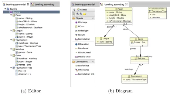
The Eclipse Modeling Framework (EMF) [9] provides a code generation facility for building tools and other applications based on a structured data model. A set of Java classes can be produced in Ecore after model specifications described in XML Metadata Interchange (XMI) and UML among others. EMF provides a set of functions (i.e. adapter classes and basic editor) and run-time support. Ecore is the modeling language for EMF.
The most basic elements present in Ecore to build models are the following:
• EClass - Class representation.
• EAttribute - Attribute representation, identified by name and type. • EReference - Association between two classes.
• EDataType - Type of an attribute representation.
3. Approaches to Data Modeling
(a) Editor (b) Diagram
Figure 3.6: Model representation of a bowling league.
Even though the use of EMF and Ecore is quite useful for developing applications it has some limitations for use within the space industry. Ecore does not focus on the need of knowledge in contrast with ontologies, but instead on the implemen-tation of the knowledge via software. There is no concept of disjointness axioms in Ecore nor reasoning features. Therefore, it was desired to create approaches that would combine features of both ontologies and Ecore and possibly other languages such as UML, this is referred from now on as Ecore++.
3.4.1
Ecore++
One example of this type of hybrid was demonstrated by Astrium Satellites in Germany with a research activity for the European Space Agency (ESA) [14] with the Virtual Spacecraft Design (VSD) environment [15] .
The VSD project relies on the Virtual Spacecraft Engineering Environment (VSEE) data model which is implemented by three main applications:
• Reference database (SSRDB). • Design tool (SSDE).
3. Approaches to Data Modeling
• Visualization tool (SSVT).
Figure 3.7 illustrates the key functions that are possible while modeling using the VSEE.
Figure 3.7: Key functions provided by the VSEE [15].
Another example is currently under development by a research team lead by Astrium Satellites. This approach goes further away than the VSD identifying and defining several set of requirements ideal for the support of conceptual data modeling applications in MBSE. Within this approach is intended to obtain the best of different modeling environments such as OWL ontologies, Ecore and UML. This new approach is introduced as CDMEcore [20].
3.4.2
Motivation behind Ecore++
As mentioned before, different approaches for data modeling provide different functionalities and of course bring up different limitations. Ontologies have proved to be powerful as knowledge management tools as they provide a spe-cific vocabulary and strong semantics. They allow to have high descriptivity of
3. Approaches to Data Modeling
the data to be modeled and in a natural language. However a strong limitation is the principle of the OWA, because it may require an extense time in order to specify every important detail that could be avoided with CWA.
Ecore has also proved to be an excellent language for data modeling, however its proper use require to have a certain training in software engineering as the use of natural language is not supported. Another issue with Ecore is that the elaboration of the data categories can turn difficult as they require a description of very different aspects which should have relation with each other.
For this reasons, an approach that would take the best out of different approaches can be very beneficial for data modeling in MBSE.
3.4.3
Properties of Ecore++
As discussed before, this approach takes its base from Ecore and adopts certain properties from ontologies. On one hand, in contrast with ontologies, Ecore relies on the CWA, which allows a detailed modeling of data less time consuming. On the other hand, Ecore does not have the possibility to make use of semantic rules nor reasoning and inference capabilities. Therefore a hybrid approach combines the most beneficial characteristics of both approaches. This is further discussed in Section 5.2.5.
Chapter 4
Specification of Research
4.1
Research objectives
As an objective of this thesis it was desired to identify unique properties of OWL ontologies that can be useful for data modeling as well as modeling data with an enhanced software modeling language such as Ecore, that adopted some ontology concepts for their applications in space engineering within the model-based sys-tems engineering domain.
4.2
Method
In order to have a broad understanding of the selected modeling approaches and therefore to be able to analyse them, it was necessary to make use of the selected languages to develop models which would demonstrate the main features, prop-erties and to find their limitations and opportunities.
Since the focus of this study is for its applications in space engineering and the MBSE approach, it was proposed to elaborate models with the use of data cate-gories based on a real space project. The data catecate-gories are intended to give a detailed description of different items that compose a spacecraft and to show a re-lationship to each other so they can represent different points of view of a system.
4. Specification of Research
Once the models have been developed, certain characteristics of both approaches can be determined. This characteristics help to understand how the modeling was done for each approach. Consequently, certain parameters such as: implica-tions, limitations and parameters can be identified for both modeling approaches.
4.2.1
Sample Data
Data from a real spacecraft provided by Astrium Satellites in Friedrichshafen, Germany was used for the creation of the models. The satellite is referred as GravitySat.
4.2.2
Selection of Language and Tool
4.2.2.1 OWL/Prot´eg´e
In terms of ontology editors, the tools available are usually specific to the ontol-ogy language. The reasons why OWL was chosen as the ontolontol-ogy language were explained in Section 3.3.2. Prot´eg´e was designed for this language and as well adds extended functionalities through the use of plug-ins [19].
Prot´eg´e is a free, open source ontology editor developed for constructing domain models and knowledge-based applications with ontologies. Currently it is used by a wide community of academics and developers which provides continuous and updated support of the tool. The Prot´eg´e-OWL editor allows to create OWL and RDF ontologies and provides the following functionalities, among others [16]:
• Exploration of classes, properties and individuals. • Visualisation plug-ins such as Jambalaya or OWLViz. • Support for queries and rule languages such as SQWRL.
4. Specification of Research
• Execution of reasoners such as Pellet or DIG.
Hence, this ontology editor is used in this thesis. In particular the Prot´eg´e Desk-top 3.5 version for MacOSX platform was used.
4.2.2.2 Ecore-Based/SSDE
The SSDE has been validated by ESA with a demonstration of this software using data from the GOCE mission. As explained in Section 3.4.3, the tool is divided in tree blocks which allow different functionalities. In particular it results really handy to model from graphical editors from which Topological Design, Opera-tional Modes and Activities, FuncOpera-tional Design and AIT Design are within the possibilities [15].
SSDE integrates the QUDV model, which allow to have a common definition for the quantities and units used in a set of models [34]. This results quite useful while dealing with multiple actors involved in one project. It is also possible to import physical properties from a CATIA model into a VSEE model.
It is possible to explore the model by diagrams, trees or tables, making the de-sired information easy to find and use. SSDE also allows the posibility of 2D and 3D visualisation which help activities such as Modeling Design Review, Analysis Result Review, Physical Design Review and Simulation.
4.2.3
Approach
As proposed in the objectives for this work, it was important to analyse and estab-lish a fine-granularity of ontology technologies for data modeling, in other words to breakdown the different properties and implications of ontologies. Therefore it was of high significance to define data categories to be modeled using the data from the spacecraft which will reflect the relationship between different system
4. Specification of Research
levels, and cycles of a space project. This implies having a complete breakdown of the several systems comprising a spacecraft. It was intended to show the support of these approaches in MBSE for space engineering.
4.2.3.1 Modeling engineering data using both approaches The proposed model is the following:
A description of the GravitySat’s mission phases, the operation modes and Attitude and Orbital Control System (AOCS) components re-quired (status) for each of the latter.
In order to be able to develop the proposed model, five data categories were cre-ated: • Components • Discipline • Engineering • Mission Phases • System Operations
Components - Contains the spacecraft elements from a component perspective. First, there is a division between Space Segment components and Ground Seg-ment components. The Space SegSeg-ment components are organized according to their subsystem (AOCS, EPS, OBC, OBS, etc.). Referring specifically to AOCS components the classification is done according to the type of components: Ac-tuator, Sensor or Thruster (even though the thruster system is considered as an
4. Specification of Research
actuator, due to its complexity it is considered separately).
Discipline - Contains a classification according to space engineering disciplines, such as: electrical and optical engineering, mechanical engineering, software engi-neering, etc. For this model, there is a special emphasis on hardware which itself is divided in mechanical and electrical components.
Engineering - Contains the spacecraft elements according to their engineering as-pect, such as: functional design element, operational design element and system element. System element comprises a division of element definition and element occurrences. The element definition provides the definition in an abstract level of each of the components of the spacecraft. While the element occurrence includes every single component modeled in the spacecraft.
Mission Phases - Contains all the Mission phases: Operational, LEOP, Pre-Launch, End of Life and Commissioning.
System Operations - Contains the Operation Modes of the satellite divided by Nominal and Non-nominal. Nominal: Launch, Separation, Early Orbit, Nominal Operation, Calibration and Orbit Manoeuvre. Non-nominal: Launch Contin-gency, Safe and Failure.
The correct operation of GravitySat during its mission phases depend on a set of satellite operation modes. Each of these modes represent stable hardware and software configurations with all the sub-systems and components involved. Fig-ure 4.1 represents which operation modes exist within every mission phase.
4.2.3.2 Pointing out the characteristics of the models
While modeling the data it is important to determine certain characteristics of the models in order to have a better understanding of the approach used. Once the model was proposed and the data categories were defined, certain
characteris-4. Specification of Research
Figure 4.1: Satellite Operation Modes vs. Mission Phases.
tics arise for each of the approaches. One example is that, while using ontologies, some individuals are members to different classes at the same time because of the properties. This shows how the different categories are related to each other. These characteristics are pointed out for each of the models.
4.2.3.3 Deriving implications, limitations, and opportunities
Developing the models with the selected approaches intends to identify implica-tions, limitations and opportunities that are inherent to the used tools. These parameters are discussed for each of the models. For purpose of this work, these parameters are defined as:
• Implications - Conclusions that can be drawn from modeling with a tool that are not necessarily implicit or the way how the modeling had to be done.
• Limitations - Drawbacks while modeling using the the selected tools. • Opportunities - Benefits for data modeling discovered while using the
Chapter 5
Description and Analysis of
Research
5.1
OWL
5.1.1
Model description
This model intends to represent the defined data categories in Section 4.2.3.1. The ontology is based in the Space Systems Design Ontology [19] and the VSD [15].
The data categories are represented as classes which are labeled as aspects and are illustrated using the OWLViz plugin from the Prot´eg´e editor with all of their subclasses. Figure 5.1 shows how the Component Aspect is defined while Figure 5.2 and Figure 5.3 represent the Discipline Aspect and Engineering Aspect re-spectively.
The Mission Phase Aspect and Systems Operations Aspect are illustrated in Fig-ure 5.4 and FigFig-ure 5.5. Is important to mention that the relationship between these two aspects is clearly defined in Figure 4.1.
5. Description and analysis of research
Figure 5.1: Component Aspect Visualization.
Figure 5.2: Discipline Aspect Visualization.
5. Description and analysis of research
Figure 5.4: Mission Phases Aspect Visualization.
Figure 5.5: System Operations Aspect Visualization.
5.1.2
Model characteristics
In order to make the desired representation mentioned in the previous chapter, it was important to make a detailed model of the components that belong to the AOCS subsystem. For this purpose, it was decided to model the components as individuals and here is where the relationship between aspects becomes necessary.
From the individuals point of view, taking as an example a magnetic torquer (MTQ). It is possible to say that it is a component that belongs to the AOCS subsystem (Component Aspect), but it also needs to be defined as an element (Engineering Aspect), and since it has electrical and mechanical properties, i.e. mass, then it is also considered as a mechanical component which is also a hard-ware component (Discipline Aspect). And last but not least it is possible to know in which modes (System Operations Aspect) of the mission is involved (on or off ). Figure 5.6 illustrates how the MTQ-1 is modeled.
5. Description and analysis of research
5. Description and analysis of research
model is to consider the calibration mode. It can be seen from Figure 5.7 to which phases (Mission Phase Aspect) of the mission this operational mode belongs as well as which status the components from the AOCS have (on, off, enabled, dis-abled, open and closed ).
Figure 5.7: System Operations - Calibration-A.
5.1.3
Implications
One way of exploiting the use of inferences in OWL is through the use of SQWRL rules with the help of the Drools rule engine. Its use is demonstrated in the model with the following example.
The mechanical components classification is still empty as nothing was defined to be a mechanical component. For this case, two rules are created and shown in
5. Description and analysis of research
Figure 5.8. These rules state that every component found in the ontology which has a mass, should be considered also as a mechanical component.
Figure 5.8: Rule Example - If a component has mass then it should be considered as a mechanical component.
At first sight the use of this set of rules seems to be really useful, however this approach can only be used as forward chaining as it only creates the new relation but it does not modify the ontology and therefore there is not real inference done. The real useful characteristic comes with the use of Drools since it allows to create new inferences in the ontology. First the SQWRL rules and the OWL knowledge are transmitted to the rule engine and the rule engine is run. Figure 5.9 shows the inferred knowledge to be transmitted to the ontology once the rule engine was run.
Finally the inferred knowledge is transmitted to the ontology. And the results are shown in Figure 5.10. The inferred knowledge was transmitted to the ontology and it was overwritten with the rules specification. The mechanical components classification is updated with the inferred knowledge.
Another valuable example for the use of SQWRL is that numerical calculations are possible. For this, it is desired to establish the mass in kilograms and in pounds. However making the conversion for each element one by one can result in a tedious and prone to error task. Using SQWRL rules is possible to make the conversion for every single element and overwrite the ontology with the mass
5. Description and analysis of research
Figure 5.9: Rule Example - Drools inferred knowledge.
5. Description and analysis of research
in the different unit (conserving both). This rule and the inferred knowledge it creates are illustrated in Figure 5.11. Figure 5.12 shows a simple example of a component before and after the application of the rule and the modification of the ontology. This type of rule can be extended for converting different units (length, sensitivity, temperature, etc.) and assure no mistakes are done.
Figure 5.11: Rule Example - Conversion from kg to pounds.
As discused in Section 3.3.2.2 queries are important part of OWL. In order to show the use of queries two examples were defined:
1. It is desired to know the mass budget of all the components that conform the Cold Gas Propulsion System (CGPS) in order to know if the requirements are fulfilled. Figure 5.13 illustrates the query used. This query finds all the compo-nents which have a mass greater than 0 and that belong to CGPS, Figure 5.14 illustrates the result. This query can be modified to calculate the power budget for the same components for example.
2. It is desired to know which AOCS components are on during the Launch mode of the spacecraft. Figure 5.15 illustrates the query used. This query finds all the components which have the status on and that belong to AOCS, Figure
5. Description and analysis of research
(a) Before.
(b) After.
5. Description and analysis of research
Figure 5.13: Query 1 - Mass of all the components that belong to CGPS.
5. Description and analysis of research
5.16 illustrates the result.
Figure 5.15: Query 2 - AOCS components that are on during launch.
5. Description and analysis of research
Once the queries have been performed and results have been obtained, is possible to export the results to Excel as a csv file. The utility of the export tool from the query plugin of Prot´eg´e is that it can display the information found with the values they have, something which is not clearly visible from Figures 5.14 and 5.16 but is illustrated in Figure 5.17.
5. Description and analysis of research
5.1.4
Limitations
Probably one of the biggest limitations of modeling with this approach is that OWL ontologies are based on the OWA. It helps to keep consistency in an on-tology, facilitates reuse of information and allows any ontology to be extended. However, it might bring consequences which are not desirable for data modeling. It is always desired to have a really complete model that tries to represent reality in the most accurate way possible. Therefore, in order to build such a complete model with the OWA implies spending extensive quantities of time by trying to describe several details of what is desired to be modeled. It is possible to find everything what an ontology has but is not possible to find what an ontology does not have. The OWA avoids having a prescriptive model from which reality can be built and not the other way around.
The queries application on this tool provides valuable information on what is being modeled in the ontology. However it only displays information and is not possible to use it unless the information is exported for use with another software such as Excel. Therefore there is still a need of this type of software to assist the queries. Another limitation is that queries have to be structured in a really particular way which can be exemplified as:
• Which class? • Which property?
• Contains/not contains?, is greater than/less than?, starts/ends with? • Which individual?
However, is not possible to make queries which do not involve individuals. A different way to execute queries and apply reasoning and inference is with the use of SQWRL. But, SQWRL also provides some limitations. In order to apply complex rules they have to be written as a set of rules and not as a single one,
5. Description and analysis of research
and correspondingly they need to be applied together.
One important principle of OWL ontologies is the reuse of information and always increase the knowledge portrayed. While applying SQWRL rules for making in-ferences on the ontology it is possible to extend the knowledge trough reasoning and overwrite the ontology, but is not possible to do the opposite and remove knowledge from it. In case a rule was written erroneously, applied and overwrit-ten the ontology, then in order to correct the changes it is not possible to add and execute a new rule which will remove the false assertions. This would have to be performed manually, and in a large ontology this can result in a significant issue.
While modeling the System Operations aspect and the Mission Phases aspect, it was detected that there is not a simple way in order to model the transitions between the individuals of these aspects. For example: What needs to happen in order to change from nominal operation mode to calibration/orbit manoeu-vre/safe or failure modes? or How the transition happens from LEOP phase to commissioning phase and to operational phase? Furthermore, it was not possible to model if/then relationships in ontologies for support of the modeling of these aspects.
5.1.5
Opportunities
A really important aspect of OWL ontologies is the possibility of allowing reuse of information, which is highly desirable in the MBSE domain. An ontology can import another ontology, this means all of its classes, properties, and individuals can be used by another ontology. Due that ontologies use axioms to state facts, this translates into having well defined concepts, which is beneficial for informa-tion reuse. Also, thanks to the disjointness of classes and in combinainforma-tion with reasoning is possible to have consistent information. Therefore, it is not only reuse of information but reuse of consistent information.
5. Description and analysis of research
Components and elements that belong to certain subsystems of the satellite’s platform tend to be pretty standard. By reusing the information from another ontology is possible to have a sort of a ready made structure which can just be filled out with the desired parameters. Such as: exact number of components, mass, status, etc.
With Prot´eg´e is possible to generate EMF Java interfaces from the ontology which later can be used as a knowledge source for use while modeling with EMF.
5.2
Ecore-Based
5.2.1
Model description
As mentioned previously, the SSDE editor has already built-in a set of functions for modeling the spacecraft in different system levels. However, the use of the SSDE implies only interacting with the user model, this is a clear reference of how the data model and user model are completely separated entities unlike OWL ontologies.
The model was built similarly as the OWL, however there are some differences because of the nature of the approaches. For this model some of the data cate-gories were already defined and so, only the most important components in order to understand the model are shown. Figure 5.18 illustrates the Component As-pect and Figure 5.19 shows the hierarchical structure with what is it a sample of the Engineering Aspect (Element Definition and Ocurrence).
Figure 5.20 illustrates how the AOCS subsystem is defined as in Ecore and where is possible to define value properties such as the mass. How all the AOCS sub-sytem is defined and its Engineering Aspect is shown in Figure 5.21.
The Mission Phases are illustrated in Figure 5.22. The System Operations are il-lustrated in Figure 5.23 with their possible transitions and the triggers that allow these possible transitions. Figure 5.24 shows the relationship and dependence of
5. Description and analysis of research
Figure 5.18: Spacecraft Subsystem - Component Aspect.
5. Description and analysis of research
5. Description and analysis of research
5. Description and analysis of research
both.
Figure 5.22: Mission Phases.
How the AOCS components function during the System Operation Modes is de-picted in Figure 5.25.
5. Description and analysis of research
5. Description and analysis of research
Figure 5.24: System Operations and Mission Phases.
![Figure 2.1: Systems life cycle processes by ISO/IEC 15288 [23].](https://thumb-eu.123doks.com/thumbv2/5dokorg/5462512.141922/24.892.199.723.420.798/figure-systems-life-cycle-processes-iso-iec.webp)
![Figure 2.2: SE in context of overall project management [31].](https://thumb-eu.123doks.com/thumbv2/5dokorg/5462512.141922/25.892.210.723.222.531/figure-se-context-overall-project-management.webp)
![Figure 2.3: Typical example of a product tree [10].](https://thumb-eu.123doks.com/thumbv2/5dokorg/5462512.141922/26.892.186.768.528.1017/figure-typical-example-product-tree.webp)
![Figure 2.4: MOF Metadata Architecture [2].](https://thumb-eu.123doks.com/thumbv2/5dokorg/5462512.141922/30.892.219.715.226.526/figure-mof-metadata-architecture.webp)

![Figure 3.2: PCDU technical model description example [28].](https://thumb-eu.123doks.com/thumbv2/5dokorg/5462512.141922/34.892.162.792.214.439/figure-pcdu-technical-model-description-example.webp)
![Figure 3.3: SysML parametric diagram example [24].](https://thumb-eu.123doks.com/thumbv2/5dokorg/5462512.141922/36.892.208.714.454.841/figure-sysml-parametric-diagram-example.webp)
![Figure 3.5: Representation of the elements that conform an ontology [22].](https://thumb-eu.123doks.com/thumbv2/5dokorg/5462512.141922/40.892.250.672.225.527/figure-representation-elements-conform-ontology.webp)