Prediction of Expected Life Length
of Motor Locks
Master Thesis, Electronics
Mälardalen University
School of Innovation, Design and Engineering
Author: Johan Söderroos
Supervisor: Jens Berglund, ASSA AB
Examiner: Mikael Ekström, Mälardalen University
Eskilstuna 2010
i
ABSTRACT
ASSA AB develops different types of products that can be used in or around doors. ASSA offers a complete door solution to the customers. Many of these products are linked together and work for a complete formation of access control. ASSA has recently developed a new communications bus for some of their products. One advantage of the new communication bus is that each product should be able to offer different kinds of added values to the customers.
This master thesis main focus is to find a model to describe the predicted life length of ASSA:s motor lock called 811C50, which includes a study that determine which environmental parameters that can affects the motor locks life length. This master thesis is also a pre-study for further work of an existing motor lock.
The chosen test model, full parameter test, leads to a life length equation. This equation shall later on be implemented in the motor locks so the motor locks itself can predict its own life length. To make the equation completed different parameters, that can affect the motor locks life length, are needed. This can be implemented through different technological tests and to succeed with the test, right test equipment is needed. No establish test equipment was available, which required that new test equipment, which could test all motor locks, were build. On the bases from interviews with engineers at ASSA it was established that the following parameters probably can affect the motor locks life length: temperature, air humidity, dust, corrosion, side load and vibration. Not until certain factors and coefficients have been determined, for the equation, can the equation be used.
Keywords: Motor lock, Hi-O, full parameter test, reduced parameter test,
ii
SAMMANFATTNING
ASSA AB är ett företag som utvecklar olika typer av produkter som kan användas i eller runt en dörr. ASSA erbjuder en komplett dörrlösning till kunderna. Många av de här produkterna är sammankopplade och arbetar tillsammans för att komplett passersystem. ASSA har nyligen utvecklat en ny kommunikationsbuss för några av deras produkter. En fördel med den nya kommunikationsbussen är att varje produkt kan ge ett ökat mervärde för slutkunden.
Denna avhandling har som huvudsyfte att hitta en modell som kan beskriva livslängden för ASSA:s motorlås, 811C50. Till detta görs en studie för att undersöka vilka miljö parametrar som kan påverka motorlåsets livslängd. Denna avhandling kan även ses som en förstudie där målet är att vidareutveckla det befintliga motorlåset.
Den valda modellen, full variabel test, leder till en livslängdsekvation. Denna ekvation kommer sedan att bli implementerad i motorlåset så att låset själv kan prediktera sin egen livslängd. För att göra ekvationen komplett behövs olika parameterr som kan påverka motorlåsets livslängd identifieras. Detta kan ske genom olika tekniska test och för att lyckas med testen krävs rätt testutrustning. Ingen befintlig testutrustning fanns tillgänglig vilket resulterade i en ny testutrustning som kunde testa alla motorlås utvecklades. Utifrån intervjuer med ingenjörer på ASSA kunde det fastställas att följande parameterr troligtvis kan påverka motorlåsets livslängd: temperatur, luftfuktighet, damm, korrosion, listtryck och vibrationer. Inte förens koefficienter, till ekvationen, har blivit fastställda är ekvationen färdig att användas.
Nyckelord: Motorlås, Hi-O, full variabel test, reducerad variabel test, prediktion,
iii
ACKNOWLEDGMENTS
I would like to thank my supervisor, Jens Berglund, for his continuous support, encouragement and guidance through the work with this master thesis.
I gratefully thank my family, without them I would never be where I am today. I would also like to thank my dear love for supporting and help with the disposition for this thesis.
Special thanks also to the following people:
Anna Fedyszak-Koszela Lecturer at Mälardalen University
Mikael Ekström Senior lecturer at Mälardalen University
I would once again like to thank these people and everybody else at the technical division at ASSA that have contributed this master thesis.
Thank you all! Johan Söderroos
iv
GLOSSARY
English Svenska
Hook bolt Regel
Control central Endörrcentral
Strike Låsbleck
Side load Listtryck
Hinge Gångjärn
Motor gear head Växellåda
Forend Stolpe
Crank shaft Vevaxel
Access control system Passersystem Swipe card/Entry card Passerkort
Thumb turn Vred
Backset Dorndjup
Abbreviations
CAN Controller Area Network
Hi-O Highly intelligent Opening
DMS Door Monitoring Switch
v
CONTENTS
1 REGISTER ... 1 1.1FIGURE REGISTER ... 1 1.2TABLE REGISTER... 1 1.3EQUATION REGISTER ... 1 1.3GRAPH REGISTER ... 1 1.4SCHEME REGISTER ... 1 2. INTRODUCTION ... 2 2.1COMPANY HISTORY ... 2 2.2PROBLEM BACKGROUND ... 3 2.3PRODUCT BACKGROUND ... 32.3.1 The motor lock ... 4
2.3.2 Control central ... 5 2.3.3 CANopen, Hi-O ... 6 2.3.4 Product overview ... 7 3. AIM OF PROJECT ... 8 3.1PROBLEM FORMULATION ... 8 3.2PROJECT LIMITATIONS ... 8 4. METHOD ... 9 4.1AFFECTING PARAMETERS ... 9 4.2CHOSE OF MODEL ... 9
4.3LIFE LENGTH EQUATION ... 10
4.4TEST EQUIPMENT ... 11 4.4.1 Vibration ... 12 4.4.2 Side load ... 13 4.4.3 Measuring cycles ... 13 4.4.4 Current measurement ... 14 4.4.5 Computer Logs ... 15 5. RESULTS ... 16 5.1AFFECTING PARAMETERS ... 16
5.2FULL PARAMETER TEST ... 17
5.3LIFE LENGTH EQUATION ... 18
5.3.1 Life length effect ... 20
5.3.2 Completed life length equation ... 20
5.4TEST EQUIPMENT ... 21
5.4.1 Programs ... 23
6. DISCUSSION ... 24
6.1PARAMETERS ... 24
6.2FULL PARAMETER TEST AND LIFE LENGTH EQUATION ... 24
6.2.1 Calculations of coefficients ... 25
6.2.2 Use of life length equation ... 26
6.4TEST EQUIPMENT ... 26
6.5FURTHER PROSPECTIVE ... 27
6.5.1 Analyze of test result ... 27
7. CONCLUSIONS ... 28
1
1 REGISTER
1.1 Figure register
Figure 1 ASSA History ... 2
Figure 2 Control Central ... 5
Figure 3 Hi-O logo type ... 6
Figure 4 Hi-O products ... 6
Figure 5 System overview ... 7
Figure 6 Vibrator engine ... 12
Figure 7 Side load ... 13
Figure 8 External resistance ... 14
Figure 9 Full parameter test of three parameters ... 17
Figure 10 Cycle diagram ... 18
Figure 11 Cycle diagram for a motor lock with a side load ... 18
Figure 12 Hi-O hub ... 21
Figure 13 S3030S power supply ... 22
1.2 Table register
Table 1 Full parameter test of three parameters ... 17Table 2 Test setup ... 19
1.3 Equation register
Equation 1 Current ... 14Equation 2 In voltage... 14
Equation 3 Life length effect ... 20
Equation 4 Predicted life length ... 20
Equation 5 Given linear equation ... 25
Equation 6 Temperature coefficient ... 25
1.3 Graph register
Graph 1 Vibrator engine pulse ... 12Graph 2 Function of coefficient for temperature ... 25
1.4 Scheme register
Scheme 1 Circuit diagram ... 14Scheme 2 Network for test equipment ... 21
2
2. INTRODUCTION
This chapter gives you an introduction of this master thesis and a short summary of the company history.
2.1 Company history
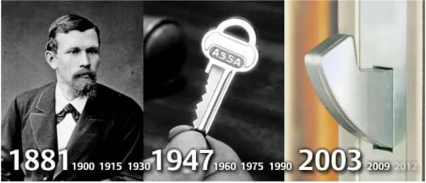
ASSA AB was at the beginning named August Stenman AB and was founded 1881 in Eskilstuna, Sweden and grounded of August Stenman. At the beginning the company produced hinges and developed the hinges industry to become market-leaders of producing hinges. In year 1910 the company developed the production to include screw. At the beginning the company only produced screws for the company it self but later on the screw production started to sell over the whole world. In year 1939 ASSA AB bought K.S.Thulins Lock and Metal factory and the first step into lock production was made1.
In 1946 the first safety system with five pin cylinders came and it becomes a very big hit for ASSA. In the sixties ASSA developed and produced all locks to car industries, both SAAB and Volvo. In the middle of 1970 the screw production closed down. Now the locks and hinges were the most sold product. “The lion of locks” is one of ASSAs slogans it’s a lock with a twin system that combines the best from old locks with the best from new locks. In 1988 the security company Securitas AB bought ASSA. Two years later ASSA split into two companies ASSA AB and ASSA Industry AB. ASSA ABLOY was founded 1994 and are now global leader in door solutions1.
Figure 1 ASSA History
(Source: www.assa.se)
1 www.assa.se 2009-12-20
3
2.2 Problem background
Just recently ASSA AB has developed a new communication bus, based on CAN bus technology, for their new products. One of many new features is that every product with the new bus shall give the user a prediction of their product life length, time for service or reparation2.
The new products are good not only for the customers, it’s also good for ASSA AB since they can analyze the broken motor locks and increase the quality and also improve prediction of life length. A motor lock that can predict its own life length has never been seen on the market2.
One example of increase customer value:
It can be expansive for customers if a motor lock break down occur out in the field and the customer need to hire security personal to guard the unlocked door. With a prediction of life length the motor lock can be changed before a breakdown occur2.
2.3 Product background
This chapter considers product background information of two products that will be used in this master thesis. This chapter will also describe ASSAs
communication system. An overview will follow that shows how the products can be connected.
4
2.3.1 The motor lock
The motor locks that will be tested in this project are motorized hook bolt locks from ASSA which are called 811C50.
ASSA recently developed the motor lock 811C50 to give the customer a good motor lock with a lot of extra functions, see features below. The new motor lock is able to communicate with for example a control central or other ASSA ABLOY products over CAN bus. Motor locks are usually installed in high security doors in an office or industrial environment. The motor lock suits different kinds of door solutions from sliding doors to double doors and also some fire protective doors. The motor lock is normally connected to an access control system or a control central to operate3.
Features
Fast unlocking time, less than 1/3 sec.
In case of power loss or another problem with the lock a cylinder or thumb turn provides mechanical override.
DMS (Door Monitoring Switch) is built-in but can be replaced or complemented with an external DMS.
35, 50 or 70mm backset option3. Technical specifications
Voltage 12-24VDC Current Idle 65mA
Max 200mA at 24V
Door gap Maximum gap between lock and strike, 6mm
Environment Temp -40°C - +70°C
Relative air humidity 20-90%3
3 www.assa.se 2009-08-25
5
2.3.2 Control central
Control central, LCU9101, is a unit for the access control system and can be connected directly to an existing TCP/IP network. The control central is prepared to be a host in a complete door system with components that supports CAN bus4.
A LD400397D I/O card can be connected to the control central to read both analog and digital signals from different kinds of sensors5.
Security is an important issue and the control central uses an encrypted communication solution patented by ASSA. The encryption ensures that no one else than the access control system can read or write the information from the control central. The control central has a lot of memory, it can handle up to 100 000 entry cards, 30 000 log events, a huge number of schedules, calendars and day types can be stored4.
Technical specifications
Voltage 17 – 35 VAC
24– 50 VDC
Current Idle 100mA at 24VDC
Operating system Linux
Flash memory 32 MB
RAM memory 32 MB
Ethernet 10/100 Megabit
Environment Temp +5°C - +40°C
Relative air humidity 20-90%.4
Figure 2 Control Central
(Source: www.assa.se)
4 www.assa.se 2009-09-21
6
2.
3.3 CANopen, Hi-O
CANopen is an organization that provides communication protocols that have an open source code for members and is built on CAN technology. ASSA ABLOY is a member of CANopen and have developed their own profile named, Building door control, on top of that ASSA ABLOY have made their own group specific protocol called Hi-O with specific functions6.
In every Hi-O net a termination resistor is needed to ensure that the bus gets the correct DC level and to remove signal
reflections. Hi-O is a standard that is used in the whole corporate group ASSA ABLOY. All Hi-O products from all companies in the corporate group can communicate with each other. The connection cable have only got four wires, two for Hi-O communication and two for power supply. In one Hi-O network there is a maximum of 32 nodes6.
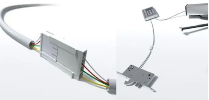
Figure 4 Hi-O products
(Source: www.assa.se)
6Meeting with Jens Berglund,Development enginer, ASSA AB, 2009-10-01
7
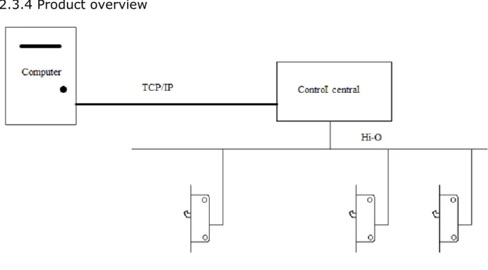
2.3.4 Product overview
Figure 5 illustrates how the products of this master thesis will be linked and work together to send information from the motor locks to a computer. Control central, as described in more detail in chapter 2.3.2, reads data from the motor locks in a Hi-O network. Hi-O is a communication system which has been described in more detail in chapter 2.3.3. The control central is sending information through the TCP / IP network to the connected computer. In Figure 5 appears three locks, but in reality it is possible to connect up to 31 locks to the control central.
8
3. AIM OF PROJECT
This master thesis main focus to find a model that can describe the predicted life length of ASSA:s motor lock 811C50.
3.1 Problem formulation
Tasks that must be solved to achieve the aim of the master thesis are: Which parameters can affect the motor locks life length?
Which model can describe the life length of the motor locks, with an equation that´s using input from the affecting parameters?
How does the life length equation operate?
Which type of test equipment is needed in order to test the motor locks life length and how does it operate?
3.2 Project limitations
The project main limitation is time, 20 full working weeks. The life length model is suited only for one type of motor lock. Also the number of motor locks in the project has been limited to 40 motor locks.
9
4. METHOD
This chapter illustrates how and what methods have been used to arrive the result. The following section will therefore consider a part for each issue.
4.1 Affecting parameters
Sooner or later all motor locks will eventually break and to find the underlying parameters that cause these breakdowns interviews with ASSA engineers in the technical department were conducted. The parameters that where discussed was temperature, air humidity, dust, corrosion, vibration and side load. From this parameters it´s decided that temperature, side load and vibrations probably has most impact on the motor locks life length.
From the interviews there were also tell that the motor locks current can increase when the motor lock is close to a break down.
4.2 Chose of model
To choose a model that could describe the life length of the motor lock Anna Koszella7 recommended a model that should give the user an equation that
describes the predicted life length with environmental parameters as input. A research was made and two different approaches were found from the field of statistical experimental design (Hansson & Bódizs 1999).
To get reliable data for the model, it doesn’t matter which model, it’s needed to test as many motor locks as possible in every test case. A recommendation from Koszela7 was a minimum of five motor locks in each test case and totally there are
40 motor locks to use. This gives eight test cases, 40/5 = 8. In the test model there will be a maximum of eight test cases. Two models were find to choose between. The model full parameter test, which includes three parameters and the model reduced parameter test, which includes seven parameters. As written in chapter 4.1 there can be seven parameters as input to the used model. The best solution considers testing all combinations of the parameters, to illustrate how life length will be affected. This because it’s adopted that two or more parameters that are tested at the same time will affect the life length more than tested only with one parameter in each test case.
On the basis of the text above it’s decided that the model full parameter test will be used in this master thesis.
7 Meeting with Anna Kozella, University lector in mathematic, Mälardalen University, 2009-10-14
10
4.3 Life length equation
The chosen model is full parameter test and this model includes a life length equation, which can be used to calculate the motor locks life length. To see how this equation is built and operates a literature review has been made. The life length equation can calculate the life length in different ways, in this master thesis it has been chosen that the life length should be measured in how many cycles the motor lock uses during a life length. To measure the life length in cycles was considered to be the best way to describe the motor locks life length.
11
4.4 Test Equipment
A literature study was made to find out if there was any test equipment that could be used to test motor locks with the three parameters temperature, vibration and side load. After the research it was clear that no existing test equipment could be used for this test. Because of that test equipment was constructed.
When the test equipment was constructed some parameters and factors needed to be observed, this to make the test equipment as good as possible.
Data of testing parameters:
Temperature, tested in temperature chambers. To have as short test time as possible two test equipment’s is required one for minimum temperature and one for maximum temperature.
o Maximum, 70˚C o Minimum, -40˚C
It has to be a constant load on the hook bolt during the whole cycle and the test need to be repeatable. Maximum and minimum side load:
o Maximum, the side load has to be so big so the hook bolt can’t go in to the unlocked state.
o Minimum, no side load which implies that the hook bolt operates without friction.
In reality vibrations comes from when the door is closing and the hook bolt is vibrating in the strike. So the hook bolt should absorb the acceleration force. The vibration tests need to be repeatable. Maximum and minimum vibration:
o Maximum, acceleration level when closing the door isn’t defined yet. o Minimum, no vibration.
Following factors needs to be observed:
The test equipment has to fit into a temperature chamber with size of 0.55 * 0.55 * 0.55 [m3].
Possibility to test 40 (2*20) motor locks at the same time (two chambers). There will be two test equipment’s constructed with 20 motor locks each. The test equipment should test motor locks with different kinds of parameters, see below:
Five without vibration and with side load Five with vibration and with side load Five with vibration and without side load Five without vibration and without side load
12
Which vibration (acceleration/retardation) levels that will be achieved in the test equipment haven’t been measured yet. To be able to put vibration values into the coefficient in the life length equation, the levels must be measured and after this, it will be possible to see how repeatable the vibration tests are.4.4.1 Vibration
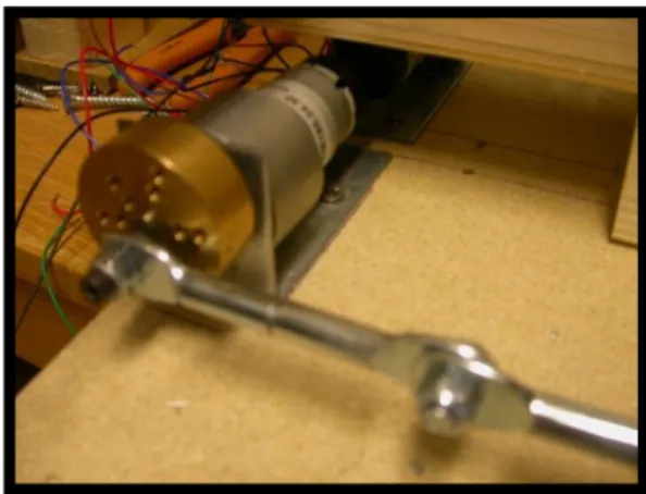
To imitate the vibrations motor lock is connected to a round threaded iron bar. Iron bar is connected to a motor via a crankshaft which moves the motor lock sideways about ±5mm. How much the motor lock is moved can be adjusted by mounting the crankshaft in different radius, see figure 6.
The frequency of the vibration depends on motor speed and can be adjusted. The vibration motor that will be used in the test equipment is a RHE158.24.30 from micro motors. It runs on 24 V and has a gear ratio of 1:30.
This motor has a position controller which uses hall sensors, that can give three pulses per revolution, see graph 1.
Graph 1 Vibrator engine pulse The position controller is needed for the motor locks that are tested for vibration
but not for side load. When the hook bolt is going from unlock state to lock state it’s required that the hook bolt don’t hit the side of the strike. If it hits the side of the strike the motor lock would be exposed for side load and the test would be wrong. So after each vibration cycle the motor has to be in a correct position so the hook bolt can go nice and easy into the strike
13
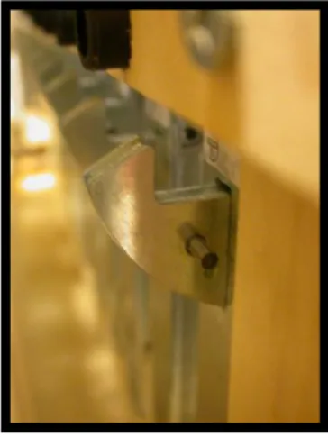
4.4.2 Side load
In this equipment the hook bolt can be moved a little bit until a fixed stop position is reached. It´s desirable to have the movement so large that the motor in the motor lock can reach the maximum speed before the hook bolt gets to stop position.
An iron bar is assembled to the hook bolt and is the stop position, see figure 7.
4.4.3 Measuring cycles
The motor lock has a counter, which counts how many cycles the motor lock has done. One cycle is when the motor lock goes from locked to unlocked and back to locked state. The control central can after that read out how many cycles the motor lock have done. When the motor locks, that should be tested, gets exposed of side load the counter stops working. To solve the problem a new application, which count the cycles, has been programmed in to the control central.
14
4.4.4 Current measurement
It can be important to have information about the supply current when analysing after a motor lock break down so the current is been calculated and logged.
The supply voltage to the motor lock is measured by itself. Supply current is calculated from the measured supply voltage (VIN). To calculate the current resistor
between power supply and the supply voltage for the motor lock is needed see figure 8. For the calculations, equation 1, knowledge about the value of the voltage from the power supply and the resistor is needed. Power supply voltage is known and has to be stable during the test. Equation 1 Current
R
V
V
I
powersupply INMeasuring and calculating in the motor lock.
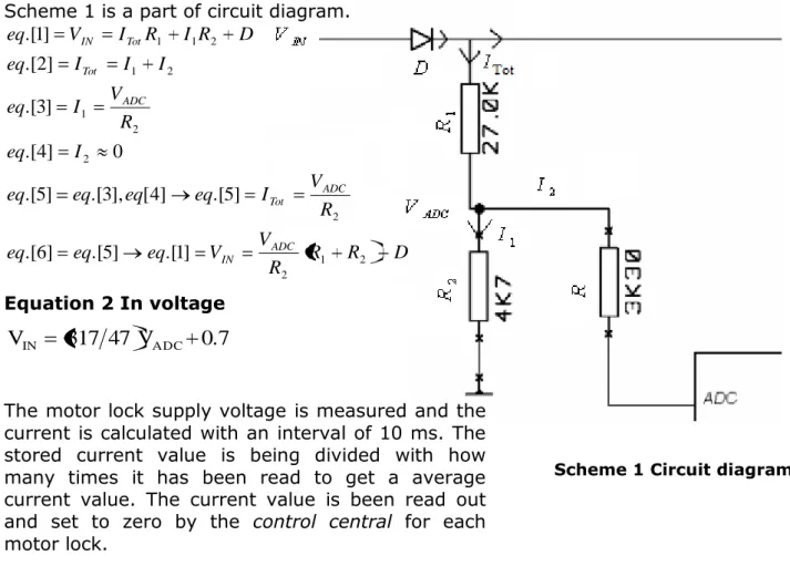
Supply voltage for the lock is measured after a polarity protection diode and the voltage over the diode is in this calculation set to be 0,7 V and is constant. Scheme 1 is a part of circuit diagram.
D R R R V V eq eq eq R V I eq eq eq eq I eq R V I eq I I I eq D R I R I V eq ADC IN ADC Tot ADC Tot Tot IN 2 1 2 2 2 2 1 2 1 2 1 1 ] 1 .[ ] 5 .[ ] 6 .[ ] 5 .[ ] 4 [ ], 3 .[ ] 5 .[ 0 ] 4 .[ ] 3 .[ ] 2 .[ ] 1 .[ Equation 2 In voltage
0.7
V
47
317
V
IN ADCThe motor lock supply voltage is measured and the current is calculated with an interval of 10 ms. The stored current value is being divided with how many times it has been read to get a average current value. The current value is been read out and set to zero by the control central for each motor lock.
Figure 8 External resistance
15
4.4.5 Computer Logs
To see how the environment affects the motor lock, logs will be written of the control central. Each motor lock is represented by one log.
Every sign written in the log is represented by one byte. In one row there are approximately 44 signs. In the logs there is a new row written for each new cycle of the motor lock. Approximately the motor lock is able to do 700 000 cycles before a breakdown8.
Example of one row in the log of a motor lock: 20100107,15:48:368,400584,21,580,123,89 Explanations of the row above:
Date: 20100107 Time: 15:48:368
Serial number: 400584 Cycles: 21
Lock time: 580 milliseconds Unlock time: 123 milliseconds
Motor lock current consumption: 89 milliamp
This implies that the size of one log is approximately: 1 Byte * 44 Signs * 700 000 cycles = 30 800 000 Bytes.
Size of one log for one motor lock is approximately 30,8MB and the total size of all logs is: 30, 8 MB * 40 logs = 1232 MB = 1,232 GB
The control central only has 32 MB flash memory and that is not enough to save all logs on, therefore a separate computer is connected to the control central. The connection between them is via the TCP/IP network. Both the control central and the computer are operating on a Linux operating system9.
8 Meeting with Jens Berglund, Development engineer, ASSA AB, 2009-08-25 9 www.assa.se 2009-09-22
16
5. RESULTS
This chapter will describe which parameters that may affect the motor locks life length and which model and equation that can be used to predict the motor lock life length. This chapter will also describe which kind of test equipment is needed in order to succeed with the model, full parameter test.
5.1 Affecting parameters
The result from the interviews concluded that the following parameters might influence the life length, see below.
Result from interview:
Temperature: Makes the metal increase and decrease in size and will increase friction between mechanical parts.
Air humidity can short circuit the circuit board, make corrosion worse and also make the lubricant to work worse.
Dust will come in into the lock and will increase the friction between mechanical parts.
Corrosion will increase friction between mechanical parts. Vibrations will also have a negative effect on the mechanics. Side load will increase friction between mechanical parts.10
10 Meeting with: Jens Berglund, Development engineer; Joachim Eriksson, Product
engineer; Peter Kropp, Project manager; Per Norling, Development engineer; Fredrik Pärus, Product developer; Lars Värlander, Product specialist, ASSA AB, 2009-09-16
17
5.2 Full parameter test
As started earlier a limited numbers of products and time is limited for this master thesis. Therefore each parameter will only be tested in two points.
The tests are done with assumption of linear dependence therefore only maximum and minimum values are tested. After each test a mean value of all the five motor locks life length will be calculated. The mean value will be the input to the life length and life effect equations
Each parameter will be tested in two points. For example: Temperature min/max
Vibration with/without Side load with/without
In the full parameter test all the parameters will be tested in 2parameters tests. With
four parameters there will be 24 =16 tests. The positive thing with this test is that
every combination of selected numbers of parameters will be tested (Bergman 1992).
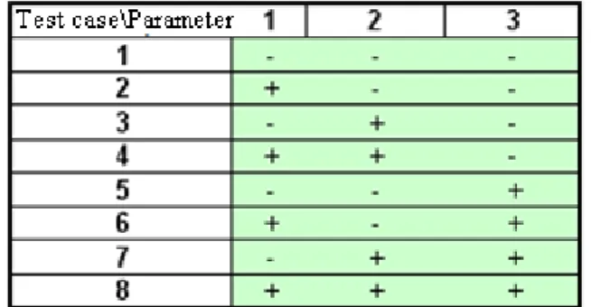
Table 1 describes a full parameter test of three parameters, the “–“sign represent the minimum test value and the “+” sign represent the maximum test value for each parameter (Bergman 1992).
Figure 9 shows full parameter test with three parameters and every test case is represented by a dot in a corner11.
11 www.thomasoberg.se, 2009-10-21 Table 1 Full parameter test of three
parameters Figure 9 Full parameter test of
three parameters
18
5.3 Life length equation
The life length is measured in how many cycles the motor lock can handle before a break down. The motor lock used in this tests has a counter included that counts every cycle. One cycle is when the motor lock goes from locked to unlocked and back to locked state see figure 1012.
Every commands lock/unlock is checked by reading status information from the lock if it has been made or not. If a command isn’t made then the lock is answered with status jam.
A problem when testing with side load is that the hook bolt isn’t moving to unlocked state and the cycles can’t therefore be counted by the motor lock. In this case the control central instead will count the cycles and in every cycle the status read back will be jam state instead of unlocked state.
12 Meeting with Jens Berglund,Development enginer, ASSA AB, 2009-10-01
Figure 11 Cycle diagram Figure 10 Cycle diagram for a motor lock with a side load
19
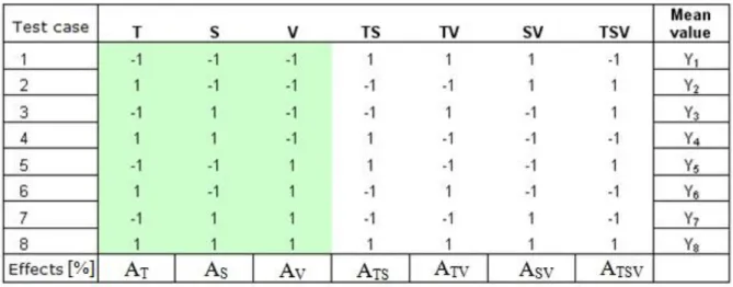
The basis of the eight test cases there will be one mean value that declares how many cycles the motor lock manages in a specific environment. When all the tests have been completed it can be calculated, according to the model, what effect each parameter have on the life length (Klemets & Lithner 1994).Table 2 shows: Marked area.
All test case combinations of maximum and minimum values for parameters T,S and V.
Unmarked area
Values is taken from marked area and calculated, for example column TS: Test case 1 T=-1, S=-1 gives TS=-1*-1=1
Test case 2 T=1, S=-1 gives TS=1*-1=-1 ...
T = Temperature S = Side load V = Vibration
TS = Temperature multiplied with side load TV = Temperature multiplied with vibration SV = Side load multiplied with vibration
TSV = Temperature multiplied with side load and multiplied with vibration
In the bottom row of table 2, effects, show how much each parameter and combinations of parameters affects the life length in per cent. Remember that the model only tests in two points for each parameter in the maximum and minimum for each parameter.
20
5.3.1 Life length effect
Equation 3 Life length effect
4 8 , 8 7 , 7 6 , 6 5 , 5 4 , 4 3 , 3 2 , 2 1 , 1 y y y y y y y y Ai i i i i i i i i [3]
(Source: Klemets & Lithner 1994) Explanations of equation 3:
i
A
= Life length effect for parameter i, i can be T,S,V,TS...k
y
= Mean life length in test case number k, in this case mean value of fivemotor locks. i
k , Maximum or minimum for parameter i in test case k represented by either -1 or 1.
Example 5 TV, 1, 5=test case number 5, TV= Column TV
5.3.2 Completed life length equation
Equation 4 Predicted life lengthV S T TSV V S SV S T TS V T TV S S V V T T
x
b
x
b
x
b
x
x
b
x
x
b
x
x
b
x
x
x
b
y
y
[4](Source: Klemets & Lithner 1994) Explanations of equation 4:
yˆ = Calculated life length, result equation 4.
8
8 7 6 5 4 3 2 1y
y
y
y
y
y
y
y
y
= Mean value for all test cases.i
x
= Parameter i, x is a normalized coefficient and is always between -1 and1.
2 i i
A
21
5.4 Test equipment
All the motor locks in a test equipment communicate, Hi-O network, with a control central. According to the Hi-O specification any bus topology can be used. For practical reasons a star topology was chosen in this case, see scheme 2.
To make the star topology possible Hi-O hubs are needed, see figure 12. The Hi-O hub used is a LD400401A from ASSA and has six Hi-O connections and one power supply connection. An Ethernet connection is also available but that will not be needed in this test. In a star topology the Hi-O termination has to be in the middle of the star so the Hi-O hub in the middle has the Hi-O termination activated. The Hi-O hubs are working in a passive mode and will therefore not affect the current consumption13.
13 Mail contact with Fredrik Blomqvist, Development engineer, Solid AB, 2009-11-05 Scheme 2 Network for test equipment
22
As power supply to the Hi-O hub aS3030S are used, see figure 13. Each Hi-O hub supplies five motor locks with power.
S3030S rated current = 3A at 30VDC Current consumption:
- Hi-O hub plus five motor locks: 5*0,2A at 24VDC
Total consumption: 1A at 24VDC
23
5.4.1 Programs
This chapter explains the extended functions in the motor lock and also a flow chart of the, see scheme 3.
Scheme 3 illustrates how the control central operates. At the beginning the control central sends a locking command to all connected motor locks. The motor lock sends back a status report to the control central. When the control central receives status from all working motor locks it reads the data locking/unlocking times, used cycles, serial number and current consumption. When data has been read it saves into logs. After the logs have been saved the control central starts the vibrate motors. The vibrate motors makes the motor locks vibrate to see how the motor lock affects. After the vibrate state there will be a timeout for the mechanics to reach there start position. After that the control central will send out a unlocking command to all motor locks. The motor lock sends back a status report to the control central before the control central can send a new locking command there will be a short time out.
24
6. DISCUSSION
This chapter will discuss each problem formulation, method, the results and a further prospective.
6.1 Parameters
The persons that contributed in the interviews have long experience from motor locks but no formal studies have been made on which parameters that affect the life length. The tests haven’t yet been made so it´s now impossible to tell which parameters that affect the motor locks. There might also be other parameters that can affect the motor locks life length.
6.2 Full parameter test and life length equation
Up to now there is assumed that there is a linear relationship between parameters and the life length, because of the parameters are tested in two points.
To give the life length equation more precision, more data can be implemented to the model, full parameter test. Now the test is only formed to test in the extreme values of three parameters. New tests can be made with testing value in the middle of the extreme values. The test can also be made with more parameters. To improve the prediction of life length it’s necessary to make more measurements between end points of the parameters.
25
11 3 ] 6 .[ 55 40 1 ] 1 [ ] 6 .[ 55 1 ] 5 [ 110 ) 40 70 ( 2 1 ] 4 [ ] 5 .[ 1 40 * 70 * 1 ] 3 .[ ] 2 [ ] 4 .[ 70 * 1 ] 3 .[ 1 40 * ] 2 .[ 40 * 1 ] 1 .[ M eq M eq k eq k eq k k eq eq k k eq eq eq M k eq k M eq M k eq6.2.1 Calculations of coefficients
Before use of the life length equation, coefficients for temperature, side load and vibrations has to be calculated.
Example of calculations for temperature coefficient:
The temperature is tested in -40°C and 70°C so the temperature coefficient -1 should referred to -40°C and 1 to 70°C. Because it’s presumed that it exist a linear relation between the two points, see graph 2, a linear equation can be given, see equation 5 below.
M e temperatur k
xtemp * [5]
Equation 5 Given linear equation
Calculations of temperature coefficient:
Result from the equations above:
11
3
*
55
1
temprature
x
temp [6]Equation 6 Temperature coefficient
26
6.2.2 Use of life length equation
Today the motor lock doesn’t have any sensors implemented to measure environmental parameters. This means that there is no meaning to implement the life length equation into the motor lock software. Instead life length data can be sent for a specific environment to the equation. If the equation by it self should be able to recalculate the remaining life length depending on changes in the environment parameters then also sensors, life length equation and new software functions need to be implemented into the motor lock.
6.4 Test equipment
Two modifications on the motor lock were needed to fit the test:
Software in the motor lock was changed to be able to measure and report the supply current for the motor lock, see chapter 4.4.3
An iron bar was assembled to motor locks in the side load test. Before testing, following factors needs to be considered:
Investigation if vibration generated in the test equipment is good enough to simulate the reality.
Investigation if vibration impact will be equally for all tested motor locks. Investigation if motor locks tested without vibration will be affected of
vibrations.
Investigate if the test equipment is good enough so that long term test can be repeated.
Long term test of the new software should be done to verify the functionality. Check if the accuracy of the supply current measurement is good enough. When the test is made, all the tested parameters has to be at a constant
level to get reliable test result.
27
6.5 Further prospective
This chapter consider a further prospective, which shows what can be done after the test.
6.5.1 Analyze of test result
When the motor lock have been tested with the parameters, temperature, side load, vibration and also combinations of these, the results can be used as input to the life length effect equation. As input to life length equation, the result from life effect equation is needed, test result data and coefficients.
Test result data is Y1- Y8, see table 2.
Coefficients is calculated in chapter 6.2.1
It’s important to analyze the result from the life length effect equation to see how much each parameter or combination of them affects the life length. If the result, for example, shows that parameter temperature doesn’t affect the life length at all or very little then this parameter was maybe wrong to use in the test.
The test result data can be analysed in Microsoft Excel. Excel has a function where data can be imported from all the log files and graphs can easily be made to see the motor locks life length in different environments. For example there can be the locking/unlocking times and how supply current is changing over life length.
28
7. CONCLUSIONS
After a literature study, where two different models were compared with each other, the model full parameter test was chosen. This model was chosen since it was considered best suited for the purpose of the master thesis and provides more reliable results.
Since there was no previous studies done on what kinds of parameters that can affect the motor locks life length, there ware conducted interviews with employed engineers at ASSA. On the bases from the interviews it was established that the following parameters probably can affect the motor locks life length: temperature, air humidity, dust, corrosion, side load and vibration. To test the parameters above the right test equipment is needed and since there was no test equipment that could be used to test the parameters that could affect the motor locks life length, test equipment was constructed.
Based on the full parameter test model, an equation is presented, which can calculate the life length of the motor locks in a specific environment. Certain coefficients most be determined for the equation so it can be completed and afterwards the tests of motor locks most be performed.
29
8 REFERENCES
[1] Hansson, M. & Bódizs, R. 1999. Kvalitetsförbättring med försöksplanering: Ett praktikfall på ytmontering vid Ericsson Mobile Communications AB. Lund: Studentlitteratur.
[2] Bergman, B. 1992. Industriell försöksplanering och robust konstruktion. Lund: Studentlitteratur.
[3] Klemets, T. & Lithner, T. 1994. Industriell försöksplanering: 13 praktikfall från svensk tillverkningsindustri. Lund: Studentlitteratur.