Multidisciplinary analysis of jet engine components
Development of methods and tools for design automatisation in a
multidisciplinary context
Tim Heikkinen
Jakob Müller
Exam Work 2015
Product Development and Materials Engineering
This exam work has been carried out at the School of Engineering in Jönköping in the subject area Product Development and Materials Engineering. The work is a part of the Master of Science programme. The authors take full responsibility for opinions, conclusions and findings presented.
Supervisor: Roland Stolt Examiner: Fredrik Elgh
Scope: 30credits
Abstract
This thesis report presents the work of analysing current challenges in Multi-disciplinary Analysis systems. Exemplary the system of an aerospace supplier, GKN Aerospace Sweden AB, is examined and several suggestions for improve-ment are impleimprove-mented. The Multidisciplinary Analysis system, with company internal name Engineering Workbench, employs a set-based approach in ex-ploring the design-space for jet engine components. A number of design cases with varied geometrical and environmental parameters is generated using Design of Experiment sampling methods. Each design case is then subjected to a set of analyses. Using the analyses results, a surrogate model of the parts behaviour in relation to the input parameters is created. This enables the product developer to get a general view of the model’s behaviour and also to react to changes in product requirements.
Design research methodology is applied to further develop the Engineering Workbench into a versatile design support system and expand the functionality to include producibility assessment. In its original state, the execution of a study requires explicit domain knowledge and programming skills in several disciplines. The execution of a study is often halted by minor process errors. Several methods to improve this status are suggested and tested. Among those are the introduction of an interface to improve the usability and expand the range of possible users. Further the integration of a four level system architecture supporting a modular structure. Producibility assessment is enabled by developing an expert system where geometrical and simulation results can be caught, analysed and evaluated to produce producibility metrics. Evaluation of the implemented solutions indicate a step in the right direction. Further development towards Multidisciplinary Optimisation, involving experts in information technologies as well as case-based reasoning techniques is suggested and discussed.
Keywords
Aerospace, Concurrent Engineering, Design of Experiment, Knowledge Based Engineering, Manufacturability Analysis System, Multidisciplinary Analysis, Set-Based Engineering
Acknowledgement
We would like to express our utmost appreciation to the entire R&T de-partment at GKN Aerospace Sweden AB for their warm welcome. Thanks to the members of the Engineering Workbench team who have put aside a great amount of time and effort to answer our questions and help us get past difficult challenges.
Among those, special thanks to Petter Andersson for helping us keep on track in an encouraging and positive manner; Roland Stolt for his support from a research related perspective; Ola Isaksson for showing us the wider context of our topic; Fredrik Kullenberg for his help with data visualisation and interpretation as well as product function and realisation insight.
This work however represents opinions and interpretations of the authors, and may not necessarily correspond with the view of the persons mentioned above.
Contents
1 Introduction 1
1.1 Background . . . 3
1.2 Industrial environment . . . 4
1.3 Purpose and research questions . . . 6
1.4 Delimitations . . . 7
1.5 Outline . . . 7
2 Theoretical background 8 2.1 Knowledge Based Engineering . . . 9
2.1.1 Artificial Intelligence . . . 9
2.1.2 MOKA . . . 11
2.2 Set-Based Concurrent Engineering . . . 12
2.3 Design of Experiment . . . 14
2.4 Simulation driven design . . . 16
2.5 Manufacturability Assessment Systems . . . 16
3 Methods 18 3.1 Success criteria . . . 19
3.2 First Descriptive Study . . . 20
3.3 Prescriptive Study . . . 20
CONTENTS
4 Results 23
4.1 Success criteria . . . 23
4.2 Initial state . . . 24
4.2.1 Challenges addressed in this thesis . . . 30
4.2.2 Active use-cases . . . 33
4.3 Process robustness . . . 34
4.3.1 Control frame and structure . . . 34
4.3.2 Inter-modular communication protocol . . . 43
4.3.3 Error Management . . . 44 4.3.4 Interface . . . 45 4.4 Producibility assessment . . . 51 4.4.1 Process description . . . 51 4.4.2 Prototype . . . 53 4.4.3 Use-case . . . 61 4.5 Evaluation . . . 66
5 Discussion and conclusions 68 5.1 Discussion of method . . . 68 5.2 Discussion of findings . . . 69 5.2.1 Process robustness . . . 72 5.2.2 Producibility . . . 74 5.3 Conclusions . . . 77 5.4 Further work . . . 80 6 Bibliography 83
CONTENTS
Index 87
List of Figures a
7 Appendices d
A Process settings file in the new EWB . . . d B Analysis settings file in the new EWB . . . e C Python function for reading parameter files . . . f D VB function for the exection of KF rules . . . g
Nomenclature
AI Artificial Intelligence
APDL Ansys Parametric Design Language BTH Blekinge Tekniska Högskola
CAE Computer-Aided Engineering
CDB Constant Database
CFD Computational Fluid Dynamics
CSS Cascading Style Sheets
DA Design Automation
DoE Design of Experiment
DRM Design Research Methodology
EWB Engineering Workbench
FEM Finite Element Method
HTML Hypertext Markup Language
ICC Intermediate Compressor Case
KBE Knowledge Based Engineering
KBS Knowledge Based System
KF Siemens NX Knowledge Fusion
MDA Multidisciplinary Analysis MDO Multidisciplinary Optimisation
MOKA Methodology and software tools Oriented to Knowledge based engineering Applications
CONTENTS
MS Microsoft
NX Siemens NX
PAS Producibility Assessment System
PDF Portable Document Format
R&T Research and Technology
RD&T Requirement, Dimensioning and Tolerance SBCE Set-Based Concurrent Engineering
Tcl Tool Command Language
TRS Turbine Rear Structure
UML Unified Modelling Language
VB Microsoft Visual Basic
VBA Microsoft Visual Basic for Application
1 Introduction
Modern day engineering combines several disciplines to create a product that withstands many criteria and fulfils a wide range of requirements. Among others, thermo-, aero- and structural disciplines strive to optimise the per-formance, longevity and effectiveness of the product. One of the challenges in product development is to find a trade off between the requirements and benefits of each of those disciplines in order to provide an optimal design that caters to the customer’s requirements [Feldhusen and Grote, 2013].
All disciplines depend on each other. For example, a change in the environ-mental temperature can lead to a change in structural behaviour and therefore make a change of material necessary. This in turn can lead to a change in producibility, and increase the overall cost. To keep track of those influences all inter-dependencies have to be analysed and visualised in a systematic way throughout the entire development process.
A major part of the development process is concerned with the cost of the product. Since most of the cost is defined at an early stage of the development process [Phillips and Srivastava, 1993] (see Figure 1.1) it is of great importance to be aware of as many inter-dependencies as possible. Though at this point in the development process it is also the most difficult to understand how different parameters affect each other. This is because of the scarce amount of knowledge available (see Figure 1.2). Also, the requirements under which the product is developed are constantly subject to change. Due to the unknown mesh of interconnections this can lead to expensive re-calculations and painfully delay the development process.
INTRODUCTION 100% 75% 50% 25% Concept development Advanced development Full-scale development Production Operation & support Time Incurred cost Committed cost Life cycle cost
Figure 1.1: Committed versus incurred cost in product development, re-produced from [Phillips and Srivastava, 1993]
.
Knowledge about the design problem 100%
75%
50%
25%
Time into design process Percentage
Design freedom
Figure 1.2: Design process paradox, reproduced from [Ullman, 1997]
.
As a result of the increased pressure on subcontractors to reduce lead-time and at the same time produce high quality as well as high performing products, the methodological approach of current product development is under rigorous research. "...it has been estimated that 85% of the problems with new products not working as they should, taking too long to bring to market, or costing too much are the result of a poor design process." [Ullman, 1997].
One interesting approach of improvement is the use of computer software to automatise the repetitive tasks involved which also enables new ways of exploring the product design space.
INTRODUCTION
The solution presented in this thesis report is described as a surrogate-based Multidisciplinary Analysis system enabled by Knowledge Based Engineering to provide early decision support. Surrogate-models , or approximation models, are used to get an understanding of a specific part of the design space and provide a base for decisions in early product development. The large number of interesting design variables demands a large amount of designs to be produced and analysed. This is not possible without the use of computer aided simulation software and automation. Knowledge Based Engineering systems are used for this exact purpose: capture and formalise engineering knowledge into software with the intention of re-use.
1.1
Background
Product development can be defined as "the process of creating or improving a product or service and managing it during all stages from design through marketing" [Heacock, 2003]. It is a part of the product life cycle and an organisational unit within companies [Feldhusen and Grote, 2013].
The introduction of computers to the product development process has, among other things, enabled advanced simulations of behaviour that previously only could be tested in real (physical) experiments. These have gone from initial verification of design to the driving force behind [Karlberg et al., 2013]. It has been estimated that up to 80% of the product development process involves repetitive and tedious tasks [Stokes, 2001]. To improve the efficiency of the product development process, automation of the simulations and its related processes have been developed. Successful implementations can be found in literature, such as [Johansson, 2014] [Soderberg and Lindkvist, 1999] [Sunnersjö et al., 2006] [Cui and Wang, 2013]. Ranging from automated FEM model creation, assembly robustness assessments and cost estimations to full structural optimisation. However, there is no widespread implementation into industry [Tarkian, 2012]. This is why this thesis work analyses the current challenges in design automation. With special focus on Multidisciplinary Analysis systems, where several automation tools are connected, by the example of Engineering Workbench at GKN.
Design automation has been used since the 1970’s within the aerospace industries [der Velden, 2008]. Discipline specific applications were developed by different teams and have gradually been generalised through the years.
INTRODUCTION
the purpose to combine different automation tools into one system where Multidisciplinary Analysis could be run. The Engineering Workbench (EWB) is constructed to provide engineers with the ability to generate variations of a design concept and to provide information about their difference in performance aspects. Examples of which are thermal robustness, structural stability (e.g. buckling, stiffness, life) and aerodynamic performance (e.g. pressure loss, swirl reduction). Challenges in the current system involve robustness and lack of producibility assessments.
1.2
Industrial environment
This thesis was written in cooperation with the R&T department of GKN Aerospace AB Trollhättan.
GKN is an international developer and supplier of technology for automotive and aerospace industry. It employs approximately 50 000 people in over 30 different countries. The product portfolio ranges from parts for civil and military aircraft engines and bodies over metal powder sintering to drive-lines for cars and products for heavy duty and utility vehicles [GKN, 2015]. GKN Aerospace AB Trollhättan was known as Volvo Aero until 2012 when it was acquired by GKN and renamed. This plant is specialised in the design of various aircraft and space engines, among others the Vulcain 2.1 engines for the Ariane 6 space rocket, the RM12 engine for the Gripen fighter aircraft and different civil aircraft engines.
Besides common engineering tools, GKN also uses the Design Automation ori-ented languages Knowledge Fusion and Journal. Due to their lesser familiarity to the general engineering community they are mentioned here briefly.
Knowledge Fusion
Knowledge Fusion is the Knowledge Based Engineering oriented extension of Siemens NXTM. "[It] is an interpreted, object-oriented, language that allows
you to add engineering knowledge to a task by creating rules which are the basic building blocks of the language." [Siemens, 2015a]. Although not visible, these rules are the same ones that are run in the background while working interactively. It is very closely integrated to the Siemens NX [Siemens, 2010]. The rules can be used to, for example, as stated in the NX Help [Siemens, 2015a]:
INTRODUCTION
• Create geometric features such as blocks, cylinder, and so on. • Carry out feature operations such as blends, hollows, and so on. • Handle expressions.
• Connect to databases and spreadsheets and thus can generate designs based on database contents.
• Manipulate User Defined Features (UDFs) thus allowing to generate and compare complex designs quickly.
These rules can then be used by programmers to perform more complex automation by creating classes. Classes can be seen as generic scripts altered by a set of inputs. The language is declarative and there are several system classes which also can be used.
Journal
"Journaling" is a method to automatise and "record [...] interactive NX sessions" [Siemens, 2015b]. It provides the user the ability to record their activity as a macro from NX in either Visual Basic or C++. Journal provides a new name space only for NX related operations to the respective language. This macro can then either be replayed in NX to repeat the recorded activity, or it can be used as basis for entire CAD routines. For the Engineering Workbench the latter one is used [Siemens, 2010]. The macros were recorded in VB and then modified and combined to create some of the scripts mentioned in this thesis.
INTRODUCTION
1.3
Purpose and research questions
In this project the challenges and possibilities of Multidisciplinary Analysis (MDA) systems are analysed. Engineering Workbench (EWB) is used as the representation of a MDA system and all research is with and about EWB at GKN Aerospace Sweden AB. The research questions is phrased as follows:
What are the current challenges of Multidisciplinary Analysis systems by the example of Engineering Workbench at GKN Aerospace Sweden AB?
The discipline of manufacture has not been represented, in contrast to thermo, aero and structural, in the Engineering Workbench. It is a major cost driver and needs to be added. A common approach in product development teams at GKN is to manually assess a limited number of concepts with domain experts. The design-space exploration characteristic of EWB studies on the other hand requires a large amount of designs to qualify statistical significance and therefore needs an automated process.
To enable automatic design assessment with regards to producibility one must find the input parameters which have an impact and define how. Those inputs then need to be retrieved and analysed by a computer software to enable automation. One part of the thesis will therefore focus on developing such a system but in the context of EWB at GKN. The research question can be formalised as follows:
How can producibility be assessed for use in a fully automated Multidisciplinary Analysis system?
A common concern brought forth when interviewing employees at GKN has been the robustness of the entire process. Software updates and moving of personal has cost some major delays in the development of EWB. The second part of the thesis will focus on improving the current system with emphasis on robustness. The research question can be formalised as follows:
How can a Multidisciplinary Analysis system be improved towards a more robust work-flow?
INTRODUCTION
1.4
Delimitations
The entire master thesis work takes place in the R&T (Research and Technol-ogy) department at GKN Aerospace AB. The work analyses the MDA system being developed in the R&T department of GKN, and it is evaluated as a representative model for a modern MDA. Due to budget and time limitations, other companies’ or academic approaches to MDA can only be analysed through literature research. The limitation on one company also restricts the use of tools and resources provided by that company.
The results of this work shall be valid as general as possible, though through the above mentioned limitations all results shall be treated carefully when regarded outside the scope of aerospace engineering. Also all part related details will be focused on the TRS and ICC structures currently handled by the MDA used and developed by GKN.
It is not the goal of this thesis to create a fully functional CAE software package. A functional prototype of an automated MDA system is developed based upon earlier developments at GKN. This prototype is developed for testing the product development related theories stated in this thesis. Even though parts of the success criteria are software robustness oriented, the software development process may not at all times be according to current software developing practice, since the creators of the software are rooted in product- and not software development.
1.5
Outline
The thesis starts with an overview of the different theories relating to the work. Followed by an overview of the systematic method applied to answer the above mentioned research questions. Then the results are presented and discussed along with conclusions drawn and suggestions for further work.
2 Theoretical background
As introduced above the development of Knowledge Based Engineering sys-tems have enabled the use of new strategies for finding better designs faster. One of which is the Engineering Workbench under investigation in this thesis. EWB is a Knowledge Based Engineering system, that employs a Set-Based Concurrent Engineering approach. With the use of Design of Experiment, it generates a surrogate model. The simulations performed in the EWB process are then used to drive the design process. For a proper generalisation in the research context the above mentioned theories are addressed below. Finally the Manufacturability Assessment System technology which is introduced as an extension of the current EWB is defined.
In our frame of reference, we found the following knowledge gap:
Robustness:
1. Robustness of real-life application of a Multidisciplinary Analysis process 2. Usage of multiple CAE systems and their abilities in the context of an
Multidisciplinary Analysis system architecture Producibility:
1. How to facilitate geometry analysis based on CAD models for the analysis of weldability.
2. Analysis of the impact of geometrical variation with respect to sustain-ability.
3. Multidisciplinary Analysis including both product performance and producibility.
THEORETICAL BACKGROUND
2.1
Knowledge Based Engineering
Engineering tasks include many repetitive and tedious tasks [Hopgood, 2000] which reduces the time spent on innovative and original engineering work. In the aerospace industry Design Automation (DA) has been introduced to improve the efficiency of the product development process [der Velden, 2008]. With DA the knowledge of engineers is captured and formalised into a computer language. Knowledge Based Engineering (KBE) is a type of DA which employs Artificial Intelligence. The development of a KBE system requires to capture and store the knowledge as well as make it retrievable. This is why many systematic methods for implementing them have been established. Much of the work done in this thesis was inspired by the MOKA methodologies and is therefore presented in more detail below in Chapter 2.1.2.
KBE focuses on reducing the time spent on repetitive tasks. [Rocca, 2012] defines KBE as:
"[KBE] is a technology based on the use of dedicated software tools called KBE systems, which are able to capture and systematically reuse product and process engineering knowledge, with the final goal of reducing time and costs of product development by means of the following:
• Automation of repetitive and non-creative design tasks
• Support of multidisciplinary design optimisation in all the phases of the design process."
2.1.1
Artificial Intelligence
Over the course of the last decades, more and more complex algorithms have been developed to perform a wide load of tasks that seem "intelligent" to the observer. Each computer is still however "only a complex calculating machine" [Hopgood, 2000], and the illusion of intelligence is generated by the speed in which computers are able to process large amounts of numbers. A Knowledge Based System (KBS) consists of at least two parts, knowledge base and control structure to process the knowledge (explained further below). Together they form a system of artificial intelligence, or AI. Incorporation of
THEORETICAL BACKGROUND
Systems for Design Automatisation
Artificial Intelligence ProgrammingConventional
Symbolic Numeric Computational Intelligence Optimization Algorithms Genetic Algorithms Neural Networks Symbolic Learning Case Based Reasoning Knowledge Based Intelligent Agents Frame Based Systems Object Oriented Rule Based Systems
Figure 2.1: Taxonomy of computer based solution principles, adapted from [Hopgood, 2000]
2008] states “Output applications from KBE processes are intelligent synthetic Knowledge Based Systems (KBSs) that incorporate process knowledge and design intent into output product models.”. He continues to say: “KBSs provide high level solutions to engineering problems that are reconfigurable to new tasks and incorporate generative principles, preserving the modelling process such that outputs can automatically update based on changes in inputs.”
[Hopgood, 2000] defines the control structure of a KBS, as "inference engine". Inference engines themselves can contain meta-knowledge about how to process the information. Inference engines act on "rules" or "functions" to process information to facts. Generally there are two kinds of inference engines, forward-chaining (or data drive) and backwards-chaining (goal-drive). A forward-chaining inference engine executes all possible rules and functions that are enabled by the information available. A backward-chaining inference engine on the other hand has a rule to solve or is asked for a specific value, and recursively solves all rules or functions necessary to get this result [Hopgood, 2000].
In a MDA system the stored knowledge consists of the routines how to perform the respective analysis, and how to handle their results. In the case of a MDA with integrated DoE such as EWB is, it may also contain knowledge about how to modify and check CAD geometry and how to mesh it. This knowledge can be stored in programming scripts or data tables. The inference engine in such a case organises the execution of process and available information in such a way that the requested results are generated.
THEORETICAL BACKGROUND
2.1.2
MOKA
Methodology and software tools Oriented to Knowledge based engineering Applications mainly focuses on reducing the cost for creating and maintaining KBE applications [Stokes, 2001].
MOKA views the KBE life-cycle as follows:
Figure 2.2: KBE life-cycle
MOKA mainly focuses on the structure of capture and formalise stages of the KBE life-cycle but emphasises the importance of each. Collect is the first step behind capture and describes the three main sources of data; experts, documentation and code. MOKA separates between consciously and unconsciously competent experts. Documentations need to be checked for validity, confidentiality and interpretation. Second step is to structure the raw data collected. Formatting should be done in a way which makes it easy for the user and KBE platform (ICARE forms, Informal models and Knowledge book). When this is done the next step is to formalise the knowledge which means that it needs to be made into computer readable language (Formal model).
THEORETICAL BACKGROUND
2.2
Set-Based Concurrent Engineering
Set-Based Concurrent Engineering or SBCE is a methodology coined by the Toyota Motor Corporation and one of the reasons of its major success in the automotive industry [Sobek I. et al., 1999].
(a) Number of design changes over
time (b)Cost over time
Figure 2.3: Concurrent Engineering process versus "over-the-wall-approach" according to [Farris, 2015].
Concurrent engineering as opposed to sequential engineering evaluates the needs of each engineering discipline during the entire development process. Traditional engineering pursues an "over-the-wall" approach, where each discipline performs its tasks towards the product realisation and then hands the design concept on to the next team. This leads often to the need for changes later in the product development process. If for example the manufacturing department can not produce the proposed design, it has to redo the entire design and analysis loop. In concurrent engineering all aspects of the entire product life-cycle are considered at all times, and those loop-backs can be avoided. This can be seen in the changes over time graph in Figure 2.3a. Therefore concurrent engineering provides an initially more complex, but eventually faster approach. This also affects the cost of the product, that grows with every necessary design change. That changes in the design become more expensive the later in the design process they are issued even increases this effect, as can be seen in Figure 2.3b.
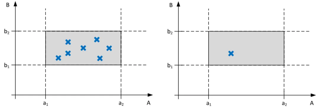
The other main characteristic of SBCE is the set-based approach, in contrast to point-based, where several designs are developed in parallel each with parameter ranges instead of set single values.
THEORETICAL BACKGROUND B A b2 b1 a1 a2 B A b2 b1 a1 a2
Figure 2.4: Set based (left) versus point based (right) design approach. The axes A and B represent parameters, and the grey area the feasible
design space satisfying the constraints a1 < A < a2 and b1 < B < b2.
A set of designs contains several approaches to fulfil the product requirements, either placed on different positions in the design space or pursuing different conceptual approaches. In Figure 2.4, the axis A and B represent two parameters, and the ranges a1− a2 and b1− b2 the constraints a1 < A < a2
and b1 < B < b2. All feasible designs have to be in the design space
highlighted in grey. The left hand graph shows a set based approach, where several solutions inside the design space are developed, whereas the right hand graph shows the traditional point based approach. Obviously, the initial effort to develop several design concepts in SBCE is higher than to develop only one design. But by exploring the design space and analysing several possible solutions, it is more likely to find a solution superior to others. Also, the availability of alternative design solutions readies the developers for potential changes in requirements at a later point in the development process. They do not have to rewind the entire development, but can fall back to a previously explored design solution.
In the case of EWB, the exploration of the design space is taken further to the point where the set of design cases is not build from single points, but an entire range. Using the results from several design cases, a surrogate model is constructed that covers an entire range of parameters. With this approach, the developer keeps track of all possible solutions in the entire parameter range.
THEORETICAL BACKGROUND B A b2 b1 a1 a2
Figure 2.5: Surrogate model of EWB generated by design points in the design space.
2.3
Design of Experiment
Design of Experiment (DoE) is a statistical method to define the correlations between the input and the output of a system or process. It models the process as a "black-box", whose behaviour is not known. It is only known that system receives an input and produces an output, and operates under the influence of a factors, controllable as well as uncontrollable ones. Such a system is displayed schematically in Figure 2.6 Only by varying the input parameters and observing the respective changes of the output parameters, the behaviour of the system is determined. Usually the behaviour of the system is then modelled in a mathematical fashion. This mathematical representation of the model is called a "Response Surface" or "Surrogate Model".
In a traditional engineering a "One-Variable-at-a-Time" approach is followed. By only varying one single parameter and observing the changes on the output, the researcher can be sure to observe only the impact of this one variable. Obviously, if the number of input- and output variables grows, the number of tests to analyse the respective correlation grows exponentially. But "this approach depends upon guesswork, luck, experience and intuition for its
success" [Antony, 2014].
DoE uses statistical methods to generate the relationship between the in-and output while varying many input variables at the same time. This input variation can be done randomly or based on specific DoE patterns.
THEORETICAL BACKGROUND
Process / System
Controllable variables (factors)
Uncontrollable variables (factors)
Input (s) Output (s)
(Y) (X1) (X2) (Xn)
(Z1) (Z2) ... (Zn)
...
Figure 2.6: General model of a process/system [Antony, 2014].
Design of computer experiments
As in the case for EWB, computer simulations are used to mimic real (physical) experiments. The deterministic nature of simulations eliminates the modelling of uncertainty in the output. A specific set of inputs can be re-run with the same results. It is therefore important to separate the "classical" DoE from design of computer experiments [Simpson et al., 2004]. In design of computer experiments the focus is almost exclusively about filling the design space [Pronzato and Müller, 2012]. Replicates which are used to understand the random variation is not necessary and the focus becomes spreading the input parameters evenly across the design space.
There are several ways to distribute, or sample, the parameters with space-filling as the objective. Latin Hypercube is a sampling method which pur-posefully precludes the non-existing "noise" or error associated with the experiments. A Latin Hypercube provides an even distribution over the entire domain by separating it into n evenly spaced domains and picking one random member from each domain [McKay et al., 1979]. At GKN, the statistical evaluation is done using statistical software packages such as ModeFrontier or JMP1.
THEORETICAL BACKGROUND
2.4
Simulation driven design
In traditional engineering, analysis and simulation is used to verify the performance of a design concept. After the development phase is finished, the design becomes subject to tests to prove its performance according to the requirements specification. The tests are simulations of regular use-cases, extreme conditions and user-interaction. Those simulations used to happen as real-world events on a prototype or the finished product, or an a model of it. With increased precision and reliability of mathematical models as well as generally available high-performance work stations the virtual analysis of design behaviour has become standard by now [Makkonen, 1999].
Though most of the time the simulations are only used to prove the design concepts behaviour. Another approach described by [Sellgren, 1995] shows "a design process where the major functions and related processes are verified and optimised with the support of computer based product model simulations". That means, that the actual design concept is shaped by the results of simulations.
2.5
Manufacturability Assessment Systems
Manufacturability Assessment Systems (MASs) have been developed to enable concurrent product development with respect to manufacturing [Shukor and Axinte, 2009]. [Shukor and Axinte, 2009] says, the general development of MASs can be divided into three main phases as shown in Figure 2.7.
The first step is about collecting the necessary information. Manufacturing information which is of interest can be extracted from CAD models, company documentations and finally the user.
When extracting information from CAD models there are several options available; exporting software independent files (such as STEP, IGES and STL), creating algorithms within the CAD software and more. To extract necessary information from users the software can simply prompt the user to answer a series of questions, this could be information that usually is not stored in CAD models such as production volume, expected surface finish and dimensional tolerance. Company documentations are saved within the MAS and represent the company specific manufacturing tools and constraints.
THEORETICAL BACKGROUND
Extract data from CAD model
User-system interaction
Collection of manufacturing information
Artificial intelligence (AI) technique o Toll for developing AI technique
o Knowledge base containing data and rules on manufacturing process
Redesign suggestions
Manufacturing processes sequencing
Selection of suitable manufacturing processes and materials
Figure 2.7: Basic methodology of MAS development [Shukor and Axinte, 2009]
Secondly this information will be used for analysing the manufacturability and can be done with or without the use of Artificial Intelligence (AI). AI techniques such as expert system are however the common approach ( [Shukor and Axinte, 2009]). The dynamic characteristic of manufacturing constraints and wishes however makes the construction of rules difficult. For early stages of product development however the level of detail is less important and general rules can be used.
Finally, depending on the level of detail in input data and to what extent it was analysed a number of different outputs could be generated. Examples of which could be redesign suggestions, selection of processes and materials, process sequencing setups, estimation of production costs and times as well as process planning setups [Shukor and Axinte, 2009].
[Venkatachalam et al., 1993] describes an expert system which chose processes depending on specific design and production parameters. These could then be used for manufacturing cost estimates.
3 Methods
The research for this thesis is concerned with the improvement of fully automated Multidisciplinary Analysis system. A common approach for testing implementations during run-time of a continuous process is action research [Williamson et al., 2002]. Action research describes one or several loops of analysis of a situation, development of an implementation, implementing it and then evaluating the impact of the implementation. A similar approach is the Design Research Methodology (DRM) as developed by [Blessing and Chakrabarti, 2009]. For this study, DRM is chosen as the methodological research framework, since it extends the scope of action research with a tool to concretely measuring the studies impact. This chapter explains DRM and how it is applied in this research.
"Considering that engineering and design are among the fastest growing fields of sciences, there is surprisingly little methodology to analyse the actual impact and quality of it" [Blessing and Chakrabarti, 2009]. Putting an end to this deplorable state of affairs, [Blessing and Chakrabarti, 2009] developed the Design Research Methodology. The research in this thesis is, with small deviations, structured after their example.
DRM is sectioned in four phases, that can, if necessary, be repeated. Similar to the cyclical engineering approach after [Wieringa, 2005] containing the five optionally repeated phases Problem Analysis, Solution Specification, Solution Analysis, Solution Implementation and Implementation Analysis, the DRM cycle is structured in four phases. The engineering cycle is displayed in Figure 3.2. The four phases of DRM shown in Figure 3.1 are explained in the following chapters. Criteria Formulation Descriptive Study I Prescriptive Study Descriptive Study II
METHODS Problem analysis Solution specification Solution analysis Solution implementation Implementation analysis
Figure 3.2: Engineering Cycle after [Wieringa, 2005]
3.1
Success criteria
Since the desired improvement is not necessarily explicitly measurable, the researcher usually has to introduce measurable success criteria. The selection of criteria should be capable of measuring negative as well as positive impacts of the implementation. To properly define the criteria is important for the entire study. As described by [Blessing and Chakrabarti, 2009] they serve to:
• identify the aim that the research is expected to fulfil and the focus of the research project;
• focus Descriptive Study I on finding the factors that contribute to or prohibit success;
• focus the Prescriptive Study on developing support that address those factors that are likely to have most influence;
• enable evaluation of the developed support (Descriptive Study II)
Though the researcher has to be aware that their implementation does not necessarily directly cause the change in success criteria. Possible side-effects or other causes have to be evaluated as possible sources for a change in criteria. The initial overall goal of this study is to find the current challenges and suggest improvements of Multidisciplinary Analysis (MDA) systems by the example of Engineering Workbench at GKN. Reasons for using a MDA is to increase the product development efficiency; create more customer value in less time. It is not considered measurable and is therefore represented with other criteria which are identified during the work.
METHODS
3.2
First Descriptive Study
After obtaining an understanding of the problem from literature, an image of the current situation is generated. By combining the results from literature and observation, the factors that influence the success criteria are identified. The descriptive study can be found in this thesis in the chapter 4.2. The information about the current situation is gathered through semi- and unstruc-tured interviews [Williamson et al., 2002] with employees of GKN relating to the Engineering Workbench.
For semi-structured interviews a number of questions are prepared and provide some structure to the interview. Five key employees stretching from developers to users of the Engineering Workbench are interviewed in this fashion; domain experts within thermal analysis (developer), parametric CAD development (developer), design of experiment (user) and computational fluid analysis (developer).
Unstructured interviews are performed as the opportunities appear at the coffee machine or while walking in the corridors.
The actual structure of the different software modules is recreated by analysing and testing the respective scripts and codes as well as reading the related documentation. Furthermore, literature research is conducted to be able to formally categorise the findings.
The findings are mapped in a standardised modelling language to be able to communicate the results.
Possible faults and/or lack in functionality are noted. The choice of which challenge to address is based on the different success criteria and the delimi-tations at present (e.g. time, available software and personal, see Chapter 1.4).
3.3
Prescriptive Study
The prescriptive study describes the desired status. One or several methods are developed to improve the status found in the descriptive study. Those methods are then implemented and tested. This is, in a research project, usually done via a demonstrator prototype or proof of concept. A demonstrator contains
METHODS
all implementations necessary to evaluate the impact of the method. A well developed prototype can be used as a basis for future implementation. This is also the case here; a desired state of the suggested improvements are presented (Figures 4.3 and 4.4) and a prototype developed to evaluate its effectiveness in succeeding to positively affect the associate success criteria.
Improved robustness
The prescriptive study for the improved system robustness of EWB is based on literature research for each single problem as identified in the first descriptive study as mentioned in Chapter 4.2.1. Finding the opportunity for improvement is dependant on the nature of each single issue. Among those is the logical deconstruction and rebuilding of the existing code, literature research to already known issues on this topic and producing new program elements. Those code elements were developed and tested for functionality in a separated loop before applying them as part of the prescriptive study.
Producibility assessment
The method used for the development of a fully automated producibility as-sessment within the Engineering Workbench is to collect information through unstructured interviews. With this information find the functional require-ments of the system and describe a viable process. Finally testing the process by developing and running a prototype system.
Literature research is a continuous process providing valuable insight in prior work within affected fields. Semi- and unstructured interviews are also continuously performed as the need arises. Once every week the progress is evaluated together with the supervisor at GKN.
3.4
Second Descriptive study
"Evaluation of design support is a complex, challenging task" [Blessing and Chakrabarti, 2009].
The second descriptive study is in its nature similar to the first descriptive study. It has to be performed with the same rigour and methods.
METHODS
The goal of the second descriptive study is to evaluate the effect of the implementations of the prescriptive study. Therefore two main questions have to be answered:
• Did the implementation of the proposed method into the current working environment succeed?
• Did the application/use of the implemented method improve the situa-tion according the the success criteria?
While evaluating the situation, caution is taken with respect to uncontrolled influences. Examples of which are company politics, software updates or other side effects.
The evaluation of EWB after the implementations of methods suggested in the prescriptive study is done as described in the following sections. The second descriptive study of this thesis can be found in Chapter ??.
Improved robustness
Most implementations were assessed in their individual impact first, and only later the entire package is evaluated as a whole. The evaluation itself is first done in via test runs with a limited number or only one single design-case. The interaction of the engineers working with EWB is observed, and their feedback is captured in interviews. As the final and most crucial element of testing, one study with 128 design-cases is run on a new TRS design. The study is used in a business case at GKN, and therefore provided suitable feedback.
Producibility assessment
The final evaluation of the suggested producibility assessment is made by measuring the identified success criteria variables as well as presenting it to affected employees and listening to their feedback.
4 Results
This chapter combines the description of the original Engineering Workbench (EWB) with the suggestions for improvement. The improvements are
mea-sured by the success criteria stated in the first section. Furthermore it explains the implementations of those improvements in detail.
4.1
Success criteria
With the implementation of new methods, the performance of EWB should improve in the following points:
Increased Usability The setup of a study shall be simpler and faster. The user should be able to customise the extend of the study to their needs. Users without extensive knowledge in programming or the software packages involved should be able to setup and perform a study. Nonetheless, a certain amount of the involved disciplines will always be necessary to achieve a useful result and interpret it. The goal is to increase the:
• Number of potential users
Analysis lead time The time between the setup and the first results. Also the overall time of one whole study should be reduced. The quantity to be limited is the:
• Set up time for an entirely new study
• Time to set up a re-run of a study with changed parameters Increased Process Reliability Once a study is started, it should continue
until all requested activities have been performed. The failure of single design cases should not jeopardise the entire study. Expressed in a quantifiable way, this results in a reduction of the:
RESULTS
Expanded Functionality Assessment of producibility shall be possible. The number of "loop-backs" between design and production should be decreased. The success is measured by an increase of the:
• Number of manufacturing constraints caught. • Number of producibility metrics caught.
4.2
Initial state
As an initial step, the original EWB is mapped in UML and represented in use-case and activity diagrams. The use-case diagrams illustrate the setup process of EWB, whereas the activity diagrams describe the process of one EWB study. The entire EWB process is shown in Figure 4.1 as a UML activity diagram.
Process
Geometry variation
The baseline geometry is varied with the help of Knowledge Fusion (KF, 1.2) classes. What they do is change NX expressions and attributes according to a Design of Experiment (DoE, 2.3) sampling method. NX expressions are used to control a portion of the geometry such as a specific length. NX attributes represent everything which is not related to the shape of the geometry, such as material specifiers or thicknesses of shell-model faces.
As a part of the geometry variation, the wet-surfaces can be varied to study different aerodynamic performances. Wet-surfaces are all surfaces in direct contact to the gas flow. This is done using an Excel Macro document, called "Volvane". Volvane is a GKN-internal script that generates vane geometries based on boundary conditions. These are directly used for the Computational Fluid Dynamics (CFD) meshing and analysis. For use in the geometry variation process however they need to be translated to the right format and then read into NX with the help of KF classes.
Meshing
To proceed with thermal and mechanical analyses on those models, the model has to be meshed. The meshing is a two step process, where first a wire-frame
RESULTS
Create DoE table
Create Wet Surface DoE table
Create Wet Surface Geometry
Convert Wet Surface Geometry
Change CAD Expressions
Include Wet Surface Geometry into CAD
Prepare Geometry for Meshing Mesh Wet Surface
Geometry CFD Analysis on Wet Surfaces Create Thermal Boundary Conditions Analysis Post Processing CAD Geometry CAD Geometry Mesh Thermal Boundary Table CFD Results
Wet Surfaces Mesh
Wet Surfaces Geometry
Wet Surfaces Geometry
Analyze Results Varied Parameters Parameters Tolerance Analysis Result Data Tag Geometry Wireframe Model Create Baseline
Concept CAD Geometry
Mesh CAD Geometry
RESULTS
model is created in Hypermesh. The wire-frame model is then converted into a mesh file and tagged as requested for the finite element method (FEM) solver used in the analysis part. In most cases, this is Ansys, so the model becomes a CDB file. This process is detailed in the "Meshing Loop" in Figure 4.1.
RDnT
Requirement, Dimensioning and Tolerance (RD&T) [Soderberg and Lindkvist, 1999] is another independent analysis used to evaluate the assembly robustness. It is a Windows-based software application that imports IGES formatted representations of the CAD geometry. After setting up an initial assembly sequence the system analyses the variations of the individual part-positions for propagation in relation to other parts. It can be used to understand where tolerance constraints are better kept free or where they are less sensitive to changes. For the purpose of Engineering Workbench studies the geometrical robustness can give an indication of potential manufacturing issues caused by highly coupled and sensitive assembly structures. This was unfortunately not used at the time and is therefore not assessed further.
Analysis
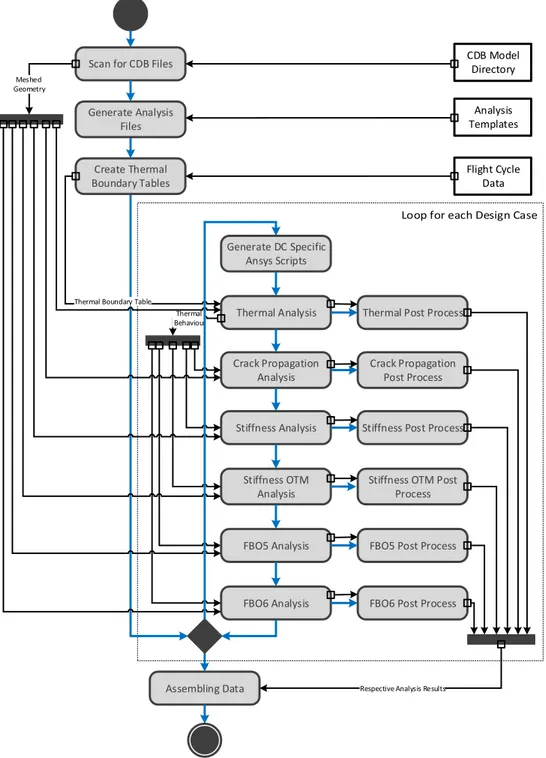
The thermal and mechanical analysis part in the original state consists of twelve Ansys scripts and one Python script that manages their execution in the right order. The Python script is called "the Master-Script" internally, and will be referred to here by the same name. The Master-Script also called a Matlab script that generates boundary tables based on copy of the original DoE-file. See the "Analysis loop" in Figure 4.2.
Initially, the analysis "Master-Script" written in Python is intended to perform several scripts depending on or independent from each other. Though so far only one analysis sequence has been executed:
1. Thermal Analysis
2. Crack propagation Analysis 3. Stiffness OTM Analysis 4. Stiffness Analysis 5. FBO5 Analysis
RESULTS
Thermal Analysis
Stiffness Analysis
Stiffness OTM Analysis
FBO5 Post Process
FBO6 Analysis Crack Propagation
Analysis
Assembling Data
Thermal Post Process
Crack Propagation Post Process
Stiffness Post Process
Stiffness OTM Post Process
FBO5 Analysis
FBO6 Post Process
Thermal Behaviour
Respective Analysis Results
Create Thermal Boundary Tables
Thermal Boundary Table
Scan for CDB Files
Flight Cycle Data CDB Model Directory Analysis Templates Generate Analysis Files Meshed Geometry Generate DC Specific Ansys Scripts
Figure 4.2: Activity diagram of analysis process in the original EWB, as performed by the "Master-Script".
RESULTS
6. FBO6 Analysis
This routine consists of the six analyses above, each including a post process to generate images of the results and to save the results into a TXT file. The entire process is detailed in Figure 4.2. The "Master-Script" works based on input directories for the analysis files and mesh files. Each directory gets scanned, and from there the script generates its process routine. The analysis files are named with a prefix of five number blocks in the pattern 11_22_33_44_55. Each block describes the level, and the number in the block the order of execution. Files of lower levels require data from the analysis with the next higher level of the same number. So the analysis file 02_03_01_00_00 requires input from the file 02_03_00_00_00. The first file is of level three (third block numbered), and requires input from the file on level two (only second block numbered) with the number 02, same as level two of the first file. This system allows for analysis in up to five levels of analysis in up to 99 cases. The Master-Script includes a short Matlab script that reads the initial flight cycle data and generates varied thermal boundary conditions based on that original input. It ends with calling another Python script that organises and assembles all the data generated during the entire analysis process. This results in the fact that the results of the analysis are only available after the last analysis and post process have finished.
Setup
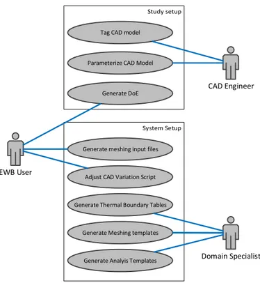
Before the above mentioned process can be started, it requires a setup process by the user. This setup process can usually not be done by a single person, since it requires explicit domain knowledge. The setup process is illustrated as a UML use-case diagram in Figure 4.3. It shows the user who wants to execute a study on the left hand side, and on the right hand side the assisting CAD-engineer and another Domain Specialist, who can represent more than one person depending on the depth of the study.
To setup an EWB study the input parameters need to be defined. They are stored in an Excel sheet and varied with a DoE sampling method, usually Latin Hypercube, to define the design matrix. The design matrix represents all the design-cases, or set of parameters values, which will be investigated. A Latin Hypercube provides an even distribution over the entire domain by separating it into n evenly spaced domains and picking one random member from each domain [McKay et al., 1979]. Latin Hypercube is used in the EWB studies because of its exploratory nature and the unknown outcome of the
RESULTS
CAD Engineer
Parameterize CAD Model
Generate DoE Tag CAD model
EWB User
Generate Analyis Templates Generate Meshing templates
Adjust CAD Variation Script
Domain Specialist
Generate meshing input files
Generate Thermal Boundary Tables
Figure 4.3: Use-case: Preparing a design study in the original EWB.
studies. In most cases at least some design-cases fail and the impact of these random failures are not as severe compared to other sampling methods. The CAD model that has to be analysed in the study is in most cases at GKN available as NX part file, since Siemens NX is the corporate CAD system. For use in EWB, the CAD model has to be converted into a shell model. The shell model then has to be parametrised. This describes the process of defining the geometry not in absolute measurements, but the position and dimensions of the geometry features relative to each other. The process of parametrisation requires, depending on the complexity of the part, several hours to several days of work from a CAD specialist. Usually several of the first approaches of the parametrisation reveal weaknesses once the geometry variation algorithm is applied, so it is a recursive process that can span far into the first test runs of the study.
For the EWB system to recognise functional features in the model, such as weld seams, load points or thermal zones the model has to be tagged with the respective names. Commonly every surface is also named to check the model for consistency during the geometry variation process.
RESULTS
To execute the geometry variation process the user has to create a specifically adapted Journal-script. In this Journal script the user assembles several KF-rules that read and apply the parameters from the DoE table, perform several consistency checks and import the respective vane geometry. On top of that, other Journal functions have to be implemented. They are discussed in further detail in Challenges addressed in this thesis on page 32. Even though this process is mostly the adaption of an already existing template, it still requires a certain skill in Journal, NX and VB.
Furthermore, a Tool Command Language (Tcl) script has to be modified by the user as an input file for the meshing process. In it the user states the number of models, their location on the file server and several meshing options. In some cases the meshing script itself has to be adapted. Since this requires a certain level of proficiency in Hypermesh, it is usually done by a domain expert.
At least two more domain expert are usually required to adapt the individual analysis scripts to the current model and analysis requests of the study. Usually within thermal and structural engineering.
4.2.1
Challenges addressed in this thesis
As a result of studying and mapping the original EWB system, several challenges for current MDA systems have been found. Some of those challenges have then been addressed in an attempt to generate a functioning MDA system integrated in a product development process. Among the challenges that have been found are:
Computational Resources For the execution of multiple analyses certain computational resources have to be available. Especially if the results shall be available in a short time.
Adaption of the system Many of the participating developers prefer to work in the discipline native environment than using the interface and system of EWB. It is also difficult to introduce system level standardisa-tion over several CAE systems and have them adapted by the respective discipline experts. This work also showed the already known issues with extracting knowledge from engineers for the purpose of setting up a KBE system.
RESULTS
Process robustness Connecting multiple CAE systems to perform an au-tonomous routine with varying input parameters poses several challenges on a programming and system level. This is detailed further in the paragraph Robustness below.
Lack of producibility assessment Even thought it is of importance in judging the feasibility of a design, the aspect of producibility and manufacturability has been neglected, at least in the system under investigation. This point is detailed below in the paragraph Producibility assessment.
Visualisation of results Due to the complexity and number of results, the visualisation of the inter-dependencies is difficult. Displaying the relationship between up to three parameters is possible in a 3D-response surface, but for more parameters new methods have to be found. Choosing which challenge to take on is based on which would impact the success criteria the most. A number of variables are taken into consideration, such as; prior knowledge, available personal and interest. The decision is to develop a way of conducting producibility assessments as well as improving the overall robustness. A short explanation of the chosen challenges are presented below.
Producibility
All disciplines taken into account addressed different performance aspects of the product. The analysis and understanding of producibility metrics such as manufacturing cost and sustainability is less developed. Only the RD&T software gives an indication of manufacturability. However as mentioned in the developers article [Soderberg and Lindkvist, 1999] an increased assembly robustness does not always indicate an improvement of manufacture. Even less so giving an indication of sustainability, which might become a great deal breaker in the future [Hallstedt et al., 2010].
Robustness
The analysis of the original EWB structure has revealed some points in the used scripts and processes that can be improved to achieve a greater robustness, usability and reproducibility of the results.
RESULTS
for a rerun in a different design study with a different model. This is mostly due to "hard-coded" names and values. "Hard-coded" can be understood as such that instead of introducing a variable and a mechanism to read the respective value procedurally, the author of the script simply read the value and typed the number in the script. Whereas this method is usually faster and produces initially the same results, as soon as the script has to be used in a different environment the hard-coded value might not be correct anymore. The script has to be adapted manually by the user to avoid wrong values. In addition to that, when writing code hastily, those hard-coded values can occur at any point in the script, and as such are sometimes very hard to find. One of those recorded-and-modified scripts is the Journal-script used to generate geometry variations from a parametrised baseline model. It performs the activities in the "Geometry Loop" in Figure 4.1. The script is written in Visual Basic (VB) , and consists in large parts of recorded macros. To explain one of the possible problems with the method of simply using recorded macros, the following scenario is explained:
This script at one point opens up each component in the assembly, to trigger the update function of the geometry for each part. This happens by addressing each of those components by its respective name. This procedure, and hence the names, are gathered through a recording on the actual CAD model. So if in a new CAD assembly is used for a study, and any of the names change, the script had to be re-recorded in NX and adapted to the batch process. Furthermore the application of geometry variation is done by several Knowl-edge Fusion (KF) rules that are governed by the above mentioned VB script. The rules are responsible for fetching the varied parameters from the Excel sheet that holds the DoE. Those KF rules are also in charge of checking the geometry for failures in recreating the modified geometry. The KF rules are not bound to a single geometry though, since they receive their required part names directly from the DoE table.
Before the geometry can get meshed, it has to be transformed from a surface model to a wireframe. This is done by the meshing script. The pre-meshing script performs a conversion of the NX assembly file to a Hypermesh wireframe file. A TCL file is created for each design-case with respectively adapted input parameters and then executed by a batch script. The actual meshing process is governed by a TCL parameter file that, again, is created specifically for each design-case and then starts a TCL script creating a CDB file. The meshing script is extremely sensitive to misalignment between the model tags and the settings in the parameter file, and often leads to a failure of the entire batch meshing process.
RESULTS
A change in what kind of analysis are performed always required the work of specialists in the respective fields.
The input for a new study was either done by changing the values of variables directly in the code and then saving and running a copy of the template script. In the case of the analysis scripts this was done in a loop for each design case. For those input parameters not value checks were implemented, so if a script for example could not find a file, the exception caused the script to halt. Since the scripts processed all the design-cases consecutively, an error in any design case led to the following cases not being processed at all. In no case a error message was created to tell the user where and why the script halted and the progress could only be estimated by the already processed files. In general, none of the scripts mentioned above created any kind of log-file to allow the user to reproduce the process or find failures.
4.2.2
Active use-cases
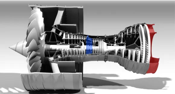
There are two active use-cases, both of which evaluate geometrical and requirements changes with respect to aerodynamic, thermodynamic and structural performance. One use-case is looking at the Turbine Rear Structure (TRS) and the other at the Intermediate Compressor Case (ICC) (see Figure
4.4).
The main functions of the TRS include carrying the turbine shaft bearing through the turbine rear mounts, fixing the turbine to the wing. It also plays a role in the aerodynamic performance of the turbine jet, since it releases the gas stream out of the engine. Though this aerodynamic impact is only minor compared to the rotating parts of the turbine. The ICC is located between the high and low pressure compressors and deals with carrying loads as well as providing space for cables and pipes.
RESULTS
Figure 4.4: Rendering of a Rolls-Royce Trent 900 Turbofan1. The ICC is highlighted in blue, the TRS is highlighted in red.
4.3
Process robustness
The development of EWB to a system that can be employed in the every-day product development process requires the work of a team including software developers and discipline specialists over a lengthy amount of time. Therefore, this can not be realised to the full extent in the course of this master thesis which is limited to a working period of 20 weeks and two people. To illustrate the potential of these suggestions, after each description of the ideal process, the actually implemented changes are described. This is done in accordance to DRM by [Blessing and Chakrabarti, 2009], where a "demonstrator or [...] proof of concept" can be used to verify the effect of the prescriptive study.
4.3.1
Control frame and structure
Considering all the possibilities for improvement mentioned in Chapter 4.2.1, a complete overhaul of the system would be recommended. After careful consideration of several potential solutions, a structure as in Figure 4.5 would be suited for a future EWB implementation. It is based on a four-layers pattern service providing architecture. The layers are sorted according to their level of abstraction and the services on each layer are of the same level
RESULTS
of abstraction. The development of this system has been done following the guidelines of [Balzert et al., 2010]. It combines all the existing and potential new modules under a control frame, that governs the process- and data-management.
Control frame Process controller
Volvane Vane Geometry creation
Executive Function
Hypermesh Meshing for Analysis Distribution of parameters inbetween different processes Process order management Error handling Geometry variation Input Interface Mesh generation Data Storage Progress Log file Error file
Design of Experiment Excel / JMP / ModeFrontierCoE Table Creation
NX CAD Geometry creation
Ansyis Structural Analysis Structural Analysis
Ansyis Structural Analysis Post
Process Ansyis Thermal Analysis Thermal Analysis VolSol CFD Analsyis Analysis VolSol CFD Meshing CFD Analysis NX Geometry Data Extraction Manufacturability Analysis Excel Process Plan Parameter Flow Request Ansyis Thermal Analysis Post
Process
Figure 4.5: Schematic illustration of the ideal EWB processes.
This control frame manages the data flow between the different modules such as geometry generation or meshing, and starts the different processes when new information is needed, acting as a backwards-chaining inference engine as defined by [Hopgood, 2000]. The user states their goals for a study, together with the available input parameters. The inference engine checks for the input required to perform the selected study. It then enquires which of those values can be provided by which process, and what input that requires in turn. After evaluating all the available input, the system is left with a list of
RESULTS
User MainFrame Process A Process B
Request of Analysis
Evaluate Required Parameters Offer of Results
Offer of Results
Request of Results Request for Input
Request of Results Request for Input Reevaluate Parameter Requirements
Reevaluate Parameter Requirements
Request of Input Input Parameters Commision Process Output Parameters Commision Process Output Parameters Return Study Results
Input Parameters
Input Parameters
Figure 4.6: UML Sequence diagram illustrating the communication be-tween the Main Frame as backwards-chaining inference engine and the process controllers.
RESULTS
EWB User
Run Study Select Study Parameters
Generate Geometry Variations
Analyse Results
Prepare Mesh
Mesh CAD Model
Run Selected Analysis
Assemble and Visualize Results <<uses>> <<uses>> <<uses>> <<uses>> <<uses>> Generate DoE <<uses>>
Figure 4.7: Use-case: Generating and retrieving analysis results from the EWB.
covered by any of the available processes nor the initial user input, the main frame enquires again at the user. This whole process is illustrated in Figure 4.6, where "Process A" and "Process B" are exemplary placeholders for any kind of EWB module. Of course all those actions are done in real-time, so there would be no actual waiting time for the user.
With the above mentioned structure, the number and complexity of the use-cases reduces drastically. This would result in a faster, simpler and less error-prone way of setting up a new study.
The process would be faster, since the user would not have to switch between different interfaces or scripts for the input of the study parameters. Also parameters shared by different processes would have to entered only once, and resulting parameters would not have to be "carried over" by hand from one process the other. This also nullifies the risk of user errors. The simplification for the user applies also for the reasons mentioned above. Since most of the original and ideal EWB activities can be executed on their own, as long as they receive the correct input parameters, a module-based architecture was chosen to be optimal. Each module would carry out its dedicated task, and communicate results and inquiries to the mainframe. This architecture
RESULTS
singular task. This is of great use for development reasons but also provides those tools to other teams that are not using EWB. The modular architecture also provides an almost limitless expansion of the functionality of EWB, so that any new kind of analysis can easily be implemented. The system is also flexible to technology- or version changes in the involved processes, for example a change in corporate meshing software would only result in a new module, and no major system changes would have to be done.
Implemented modular architecture
Control frame
Process controller
Executive Function
MS Excel Input Interface
Interface
Ansys Structural Analysis Structural Analysis AnsysStructural Analysis Post Process NX Geometry Analysis Producibility Analysis MS Excel Process Plan Geometry variation And Meshing NX
Designcase Image creation
Result files
Hypermesh
Meshing for Analysis
MS Excel Analysis interface
NX
CAD Geometry creation
MS Excel DoE Interface
Log file
Error file
Figure 4.8: Schematic illustration of the implemented EWB processes
The architecture of the actually implemented EWB is as shown in Figure 4.8. The originally intended four layer architecture was reduced to only three
![Figure 1.1: Committed versus incurred cost in product development, re- re-produced from [Phillips and Srivastava, 1993]](https://thumb-eu.123doks.com/thumbv2/5dokorg/4978151.136848/11.892.232.669.203.399/figure-committed-incurred-product-development-produced-phillips-srivastava.webp)
![Figure 2.1: Taxonomy of computer based solution principles, adapted from [Hopgood, 2000]](https://thumb-eu.123doks.com/thumbv2/5dokorg/4978151.136848/19.892.114.784.206.437/figure-taxonomy-computer-based-solution-principles-adapted-hopgood.webp)
![Figure 2.3: Concurrent Engineering process versus "over-the-wall- "over-the-wall-approach" according to [Farris, 2015].](https://thumb-eu.123doks.com/thumbv2/5dokorg/4978151.136848/21.892.153.735.315.574/figure-concurrent-engineering-process-versus-approach-according-farris.webp)

![Figure 2.6: General model of a process/system [Antony, 2014].](https://thumb-eu.123doks.com/thumbv2/5dokorg/4978151.136848/24.892.255.623.212.501/figure-general-model-process-antony.webp)