TVE 14 016 maj
Examensarbete 15 hp
Juni 2014
The potential of hemp buildings
in different climates
A comparison between a common passive house
and the hempcrete building system
Johan Ahlberg
Elza Georges
Mikael Norlén
Teknisk- naturvetenskaplig fakultet UTH-enheten Besöksadress: Ångströmlaboratoriet Lägerhyddsvägen 1 Hus 4, Plan 0 Postadress: Box 536 751 21 Uppsala Telefon: 018 – 471 30 03 Telefax: 018 – 471 30 00 Hemsida: http://www.teknat.uu.se/student
Abstract
The potential of hemp buildings in different climates
Johan Ahlberg, Elza Georges, Mikael Norlén
The aim of this bachelor thesis was to study the potential of hemp buildings in different climates. The report examines and models two different energy efficient building concepts – the more common passive house and the environmental friendly hempcrete building system. These two buildings thermal performances were then simulated and compared in different climates
followed by a brief discussion about their economic and environmental impact. The simulation was performed with the energy calculating program VIP-energy v 2.1.1 with the two models located in Kiruna, Sundsvall, Malmo, Berlin and Rome to represent the different climates. Simulations for different wall sizes and a sensitivity analysis of some significant parameters were also made. The hempcrete building system showed to have a thermal performance similar to that of passive houses in more southern climates. In the north of Sweden however the hempcrete building required up to 20 % more energy than the passive house to maintain comfortable indoor
temperatures. This deficit could be compensated for with hemp fibre insulation to augment the building envelope and U-value. Furthermore the hygrothermal material properties that were not included in the simulation can be expected to have a significant positive impact on hemp buildings relative thermal performance. With a passive house thermal performance, a healthy indoor
environment and an economically viable and environmental friendly production process hemp building demonstrated great potential in all the fields studied.
ISSN: 1650-8319, TVE 14 016 maj Examinator: Joakim Widén Ämnesgranskare: Joakim Widén Handledare: Steve Allin
Table of Contents
Table of Contents ... 0 Introduction ... 2 1. Purpose ... 3 1.1 Methodology overview ... 3 1.2 Delimitations ... 4 1.3Structure of the report ... 4 1.4
Source criticism ... 4 1.5
Background and theory ... 6 2.
Important concepts and definitions ... 6 2.1 Thermal conductivity ... 6 2.1.1 U-value ... 6 2.1.2 Heat capacity ... 7 2.1.3
Specific heat capacity ... 7 2.1.4
Volumetric heat capacity ... 7 2.1.5
Heat flow rate ... 8 2.1.6 Relative humidity ... 8 2.1.7 Hygroscopy ... 8 2.1.8 Latent heating/cooling ... 9 2.1.9
Thermal diffusivity and thermal inertia ... 9 2.1.10
Thermal effusivity ... 9 2.1.11
Energy balance ... 10 2.1.12
Building energy use ... 12 2.2
Swedish building codes ... 13 2.2.1
Passive house ... 14 2.3
History of the passive house ... 15 2.3.1 Definition ... 15 2.3.2 Certification specification. ... 18 2.3.3 Hemp ... 20 2.4
Hemp building materials ... 22 2.4.1
The limestone cycle ... 23 2.4.2
Hempcrete technical properties ... 24 2.4.3
The hempcrete building system interaction ... 25 2.4.4
Method ... 29 3.
Input ... 29 3.1
1
Heat recovery, temperatures and location ... 30 3.1.1
Building envelope... 31 3.1.2
Time schedule and operating case ... 32 3.1.3
Results ... 34 4.
Energy balance ... 34 4.1
Space heating demand ... 36 4.2
Sensitivity analysis. ... 38 4.3
Specific heat capacity ... 38 4.3.1 Air tightness ... 39 4.3.2 Discussion ... 40 5. Conclusion ... 42 6. Further studies ... 42 7. References ... 43 8.
Books and Reports ... 43 8.1 Websites... 45 8.2 Appendix A ... 50 9. Appendix B ... 56 10. Appendix C ... 58 11. Figure credits ... 59 12.
2
Introduction
1.
Today sustainable development is under close scrutiny by most nations in the
industrialized world. One of the major challenges for the environment is climate change which is no longer something to be anticipated in the future – it has already started. The evidence is in our backyard: Higher temperatures, melting glaciers, tropical storms, droughts and rising sea levels are just some of the consequences and we are running out of places to hide.1 The past decades of development have led us into a new epoch, the Anthropocene, where humans constitute the dominant driver of change to the earth system. This realization requires us to take responsibility for the sake of future generations and life systems as a whole, complying with planetary boundaries.2
In 2011 the residential sector used 18%3 of the total world energy use and contributed with as much as one third of the total global greenhouse gas emissions, primarily through the use of fossil fuels during their operational phase.4 In the European Union the numbers are different; nearly 40% of the final energy consumption is used by buildings in the public and private sector which results in 36% of all greenhouse gas emissions.5 Despite all previous efforts, the energy consumption in the residential sector increased from 3200TWh to 3600TWh between years 1990 – 2010, a growth of 12% which implies much work still has to be done.6
One way for the household sector to save energy is by utilizing passive houses. Passive houses are designed to “passively” regulate the energy demand and can be viewed as the opposite of “active” regulation through the heating system. Commonly they are built with a highly insulating building envelope to establish a controlled indoor environment. However there are other things than a materials insulating capacity that contribute to thermal performance such as thermal storage and hygroscopicity.
Hempcrete is an example of a vapour permeable or “breathable” building material that utilizes a combination of thermal and hygroscopic attributes to enable a good thermal performance as well as a healthy indoor climate. The material is a bio composite mainly consisting of hemp and lime and is also amongst other things sound- and fire resistant. Hemp is an organic, non-fossil and carbon negative product that can often be grown without herbicides, fungicides or other pesticides. It has been used for over 10,000 years7 for its strong fibres and has been estimated to have over 25,000 industrial uses.8
1 Europa – Summaries of EU legislation. Tackling climate change. http://europa.eu/ 2
Rockström, Johan et al. Ecology and Society. Planetary Boundaries: Exploring the Safe Operating
Space for Humanity (2009): p. 2-19.
3 U.S. Energy Information Administration. Frequently asked questions (2014) http://www.eia.gov/ 4 United Nations Environment Programme - Sustainable Buildings & Climate Initiative. Building and
climate change – Summary for Decision-Makers (2009): p. 2.
5 Technical Guidance – Financing the energy renovation of buildings with Cohesion Policy funding. Final
report- A study prepared for the European Commission DG Energy (2014): p. 21.
6 JRC Scientific and policy report. Energy Efficiency Status Report (2012): p. 10. 7
Hemp Industries Association. Facts. http://www.thehia.org
3
Due to the incorporation of hemp in the building material it also captures a lot of greenhouse gas emissions when carbon is locked into the building walls. 1 of hempcrete stores up to 130 resulting in a negative carbon footprint.9
Purpose
1.1
The purpose of this report is to study the potential of hemp buildings in different climates by primarily comparing the thermal performance, but also the economic and environmental impact with a more common passive house building technique in use today.
Methodology overview
1.2
The following will be addressed:
An informative study of the two different building techniques will be presented. The energy consumption for a hempcrete house and a common passive house
with identical dimensions will be modelled and simulated over a one-year period in different climates.
The impact of different wall thicknesses will be tested to study the factors contributing to the thermal potential of the different building systems in the different climate zones.
How climate affects the two building systems energy consumption as well as the impact of the different wall thicknesses will be studied.
The thermal, environmental and economic potential of hemp building will be discussed based on the background information and simulation results. Simulations
In order to simulate the energy consumption for the different building systems, VIP-energy v 2.1.1 was used.10 The software is created by the Swedish software
manufacturer StruSoft AB and uses dynamic calculation methods to calculate the energy use per hour for a modelled building over a given time period. The energy flow is being calculated with consideration taken to climate factors such as temperature, radiation from sun, humidity and wind. The different model designs were based on a small one family house example model from VIP energy and then adjusted to passive house and hempcrete building standards respectively. To evaluate the simulation results they were compared with norms and previous reports.
9 Abott, Tom. The Limecrete company LTD. Hempcrete Factsheet (2014) http://www.limecrete.co.uk/ 10
4
Delimitations
1.3
The different models used in the simulations were adjusted to represent single-family homes based on the two different building concepts. To compare different climate zones in Europe, central cities have been chosen as representatives. Most of the cities where chosen in Sweden, due to the simulation program’s default geographical limitations and the availability of regulation information.
This report uses the same definition of the household energy consumption as the
Swedish energy agency and hence does not include operational electricity use or various household electricity. The discussion about environmental and economic costs will be focused on the production phase and emissions. Hygroscopic performance and its impact on household energy consumption could not be properly taken into account in the simulations but will be discussed based on previous reports.
Structure of the report
1.4
The report begins with a background section (Ch. 2) containing important concepts and definitions (Ch. 2.1) and a brief summary of the total energy consumption and the impact of the building industry (Ch. 2.2). Energy consumption regulation codes will be reviewed in Sweden to allow for benchmarking of the different houses. This is followed by an introduction to passive houses; their construction and standards (Ch. 2.3).
Afterwards information about hemp follows regarding its properties and farming process (Ch. 2.4). The final part of the background covers the hempcrete building system (Ch. 2.5).
The methodology section explains the motivation behind the household model and simulation design in VIP-energy (Ch. 3). Finally, in the last sections of the report the simulation results will be featured (Ch.4) together with a sensitivity analysis (Ch. 5) and a comparative discussion (Ch. 6) regarding the climates effect on the relative thermal performance of the two building systems. The economic and environmental costs are also discussed with focus on emissions followed by a conclusion about the hempcrete building systems potential (Ch. 7) and an evaluation of its future prospects (Ch.8).
Source criticism
1.5
The main sources used in the report are:
The International Passive House Association (IPHA)11
and their Passipedia12 which functions as a tool where new Passive House findings from around the world are presented, as well as where the highlights of more than 20 years of research on Passive Houses are being posted.
11 International Passive House Association. http://passivehouse-international.org/ 12
5
The International Hemp Building Association (IHBA)13
, its director Steve Allin and his book Building with Hemp.
Lime Technologies from the UK who have estimated the properties for their tradical hemcrete®14 product which was used to represent the hempcrete material in the simulation.
Scott Simpson (2014)15
. An investigation of hygrothermal properties of lime-hemp and clay-lime-hemp blocks retrofitted onto light-timber frames. MSc thesis, Graduate School of the Environment, Centre for Alternative Technology, University of East London.
A few references used in the background come from less profound sources. However the information is used in an informative way and has no impact on the simulation results.
13 International Hemp Building Association. http://internationalhempbuilding.org/ 14 Lime Technology. http://lime-technology.com/
15 Simpson, Scott. University of East London. An investigation of hygrothermal properties of lime-hemp
6
Background and theory
2.
To understand the method and what will be simulated in the report, one must first understand some essentials ideas and what defines the different building concepts. Through this section the reader will be given an introduction to these important
concepts and definitions and a brief explanation of the physical principles that affect the energy balance of a building. Afterwards there will be a review of the current energy use of the building sector in Europe, some key targets for future climate goals as well as some of the building codes in Sweden. This is followed by a deeper explanation of the passive and hemp house building concepts.
Important concepts and definitions
2.1
To understand what influences the energy balance of a building it is necessary to know the basics of thermodynamics as well as some other physical laws. This chapter
provides an explanation of these concepts. All underlying formulas are included in this section to give a more complete understanding to the interested reader but will not necessarily be of importance to the general understanding of the report.
Thermal conductivity 2.1.1
Thermal conductivity (k value or λ) indicates the ability of a given material to conduct heat. Heat transfer by conduction occurs when energy flows within a material without any motion of the material. When a temperature gradient exists in a solid medium the conductive heat flow occurs in the direction of decreasing temperature. This is because energy is transferred when neighbouring molecules collide and higher temperature equates to a higher molecular energy, or more molecular movement.16
“Thermal conductivity is defined as the quantity of heat (Q) transmitted
through a unit thickness (L) in a direction normal to a surface area (A) due to a unit temperature gradient (ΔT) under steady state conditions and when the heat transfer is dependent only on the temperature gradient.” (see Equation 1)
[
] Lower values equal less conductivity and a better insulating value for the material.
U-value 2.1.2
The U-value17 measures the amount of heat loss in watts (W) per square meter of material of set thickness when the outside temperature is at least one degree lower. It is commonly used in buildings to determine if a building element such as walls, floors and
16 NDT Resource Center. Thermal Conductivity. http://www.ndt-ed.org/ 17
7
roofs has a good measure of heat loss and how well they transfer heat. A component with a low U-value has a better insulation and improves the thermal performance of the building envelope. The U-value is useful because of its way of predicting the insulation performance of an entire building with set component thicknesses so one does not have to take into account the properties of all individual materials.
To calculate the U-value firstly the Thermal resistance , is calculated, where d is the material thickness and λ the thermal conductivity.
Later the U-value is calculated by Equation 2.
[ ] Where is the sum of all the resistances of the building material in the chosen building part. For example, to reach a U-value of 0.13 for the outer wall you will need 15.8meters of concrete with a thermal conductivity of 2.1 or 6 meters of solid brick with a thermal conductivity of 0.8 .
Heat capacity 2.1.3
Heat capacity is also known as thermal capacity (C) or thermal mass. Heat capacity is defined as the amount of heat units (ΔQ) that under specified conditions must be applied to a system to increase the temperature (ΔT) of a body by one degree.18 The formula is shown in Equation 3.
[
]
Specific heat capacity 2.1.4
Physical properties are often described as an intensive property because it has many experimental and theoretical advantages. Heat capacity is describes as an intrinsic character by expressing it in relation to mass. This is then called the specific heat
capacity (c) and is described as the amount of heat required to raise the temperature of 1 kg of a substance by one degree.19 Specific heat capacity is given by Equation 4:
[
]
Volumetric heat capacity 2.1.5
Volumetric heat capacity (VHC) describes the ability of a material at a given volume to store internal energy. Because it measures the capacity per volume it can sometimes be
18
Swedish National Encyclopedia. Heat capacity. (2014) http://www.ne.se/
19
8
a better indicator of a material’s thermal storage capacity than specific heat capacity as is often the case for more lightweight insulation materials.20 See Equation 5.
[
]
Heat flow rate 2.1.6
Energy and heat flow exist whenever there exists a temperature difference in a system because all systems strive to meet thermodynamic equilibrium. The heat flow rate describes how much energy that flows between two systems per second. It is a measure of power and can be derived from Fourier’s law as seen in Equation 6:21
[ ] Relative humidity 2.1.7
Relative humidity (RH) is the ratio of the partial pressure of water vapour in an air-water mixture to the saturated vapour pressure of air-water at a prescribed temperature. The relative humidity of air depends on the temperature and pressure of the system of interest and has a non-linear relationship according to Equation 7.22
Hygroscopy
2.1.8
Hygroscopy is the ability of a substance or material to attract or hold water molecules from the air or surrounding environment. Materials with this property allow water vapour to condense on their surface and pores at less than 100% RH. This is due to vapour being attracted by electro-static forces.23 A hygroscopic material can also be called “breathable”.
20
Simpson, Scott. University of East London. An investigation of hygrothermal properties of lime-hemp
and clay-hemp blocks retrofitted onto light-timber frames. (2004): p. 17
21
The Engineering ToolBox. Conductive Heat Transfer. (2014) http://www.engineeringtoolbox.com
22 Simpson, Scott. University of East London. An investigation of hygrothermal properties of lime-hemp
and clay-hemp blocks retrofitted onto light-timber frames. (2004): p. 16
23
Simpson, Scott. University of East London. An investigation of hygrothermal properties of lime-hemp
9 Latent heating/cooling
2.1.9
When a substance changes state it either releases or absorbs energy in the form of heat while the temperature is unchanged. Latent heat24 describes the amount of heat released or absorbed during a phase transition. It is expressed as the amount of heat per unit mass of the substance undergoing the phase transition, without change of temperature. In a breathable building these effects can occur in the building envelope and latent cooling25 then measures the amount of energy necessary to dehumidify the air in the building regardless the humidity outdoors.
Thermal diffusivity and thermal inertia 2.1.10
Thermal diffusivity (α) describes the rate at which heat spreads in a material. This affects how far heat will penetrate and a lower diffusivity results in heat penetrating the material slower and more shallow.26
Thermal diffusivity is also derived from Fourir’s law and is described in Equation 8:
[
]
Where is the specific heat capacity at constant pressure.
A low diffusivity means the material has a high thermal inertia due to the slow movement of heat inside the material.
Thermal effusivity 2.1.11
Thermal effusivity (e) describes the surface heat flux – the rate at with material absorbs or emits heat through its surface. Higher effusivity results in heat flowing faster into a surface from its environment and is described in Equation 9.
√ [ ] λ = thermal conductivity, = density, c = specific heat capacity
For example rock-wool has low effusivity and shows resistance to heat. When in contact with materials with different effusivities they will feel relatively warmer or colder to you even if they are at thermal equilibrium; the one with the high effusivity is just taking heat away faster.
24 Encyclopedia Britannica. Latent heat. (2014) http://www.britannica.com/ 25 The Engineering ToolBox. Cooling Loads – Latent and Sensible Heat.
http://www.engineeringtoolbox.com/
26
10 Energy balance
2.1.12
A system in thermodynamic equilibrium is a system where there it is no (net-) flow of heat or energy between the various parts of the system. This means that the temperature is the same in all parts and that this temperature is unchanged if the system is isolated.27 Thermodynamic equilibrium can only be achieved when the system reaches its
maximum entropy. This is derived from the second law of thermodynamics, which states entropy can only increase until the maximum entropy is reached and then the system is in thermodynamic equilibrium.28
For residential houses, this implies that the entropy will always increase as the temperature will always strive to be the same as the outside temperature. The law of conservation of energy also states that energy can neither be created nor destroyed, it can only change form. So the only way the energy has to go, in order to reach
equilibrium and maximum entropy, is to flow through the building envelope. To keep the temperature at pleasant levels, heat must be supplied to compensate the energy loss in cold climates. This means that the sum of heats losses is equal to the sum of heat gains.29
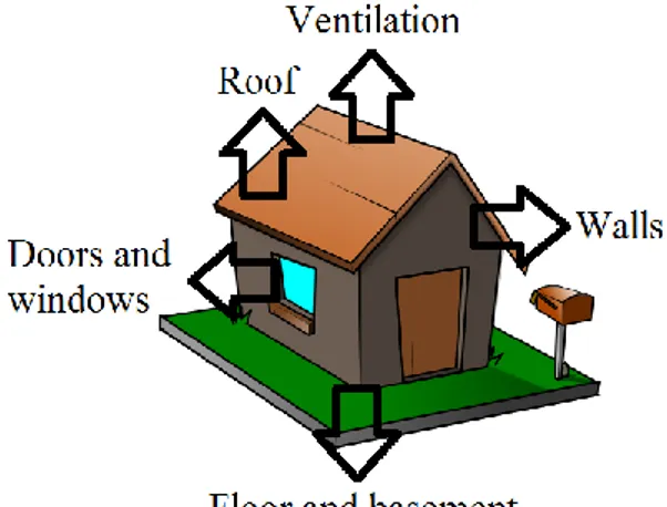
In an ordinary house in a cooler climate, the energy losses appear as shown in Figure I.
Figure I. Energy loss in an ordinary house.
The indoor climate in a house is determined by four parameters:30 The structure and design of the building
The activities inside the building The outdoor climate
The technical system that have to provide the required indoor climate.
27
Swedish National Encyclopedia. Thermodynamic equilibrium. (2014) http://www.ne.se/
28 HyperPhysics. Second Law of Thermodynamics. (2014) http://hyperphysics.phy-astr.gsu.edu/ 29 Passipedia. Energy balances – Background. http://passipedia.passiv.de/
30 Nilsson, Per. Achieving the desired indoor climate: energy efficiency aspects of systems design (2003):
11
The last parameter is only necessary if the other three are insufficient for an acceptable climate. If that is the case then the system might handle heating, ventilation and/or air conditioning (HVAC) to adjust the indoor climate. The main goal for the HVAC system is therefore to compensate heat deficit and heat surplus. However without the HVAC system the indoor temperature is determined mainly by the relationship between heat transport and generation. These are influenced by:31
1) Transport of heat through the envelope of the building. Heat is transported through the envelope of the building via heat transmission due to temperature differences, thermal bridges and air flows.
2) Storage of heat in the building structure. Due to thermal inertia heat is stored in the building structure when the room temperature rises. When the building is heated the structure slowly absorbs heat and eventually enters thermal
equilibrium. Later, when the building cools down again this heat is transmitted and thereby compensates the negative fluctuation. Radiated heat from lights, people and equipment is also absorbed by the building, stored in the structure and emitted afterwards to restore equilibrium. This leads to a delay in both heating and cooling effects.
3) Internal generation of heat in the building. Can either be solar irradiation through windows heating up the floor and walls, heat from people and activities in the room and heat generated by lighting and equipment.
31
Nilsson, Per. Achieving the desired indoor climate: energy efficiency aspects of systems design (2003): p. 301
12
Building energy use
2.2
The household energy consumption refers to the energy used for heating, cooling, tap water and operating installations such as pumps and ventilation.32 In the European Union nearly 40% of the final energy consumption is used by buildings in the public and private sector which results in 36% of all greenhouse gas emissions.33 Reducing the energy use in Europe is vital and the current policy for energy saving measures is based on the Kyoto Protocol from 1998. Three goals regarding energy efficiency were set up by the EU in 2007:34
A 20% reduction in EU greenhouse gas emissions from 1990 levels;
Raising the share of EU energy consumption produced from renewable resources to 20%;
A 20% improvement in the EU's energy efficiency.
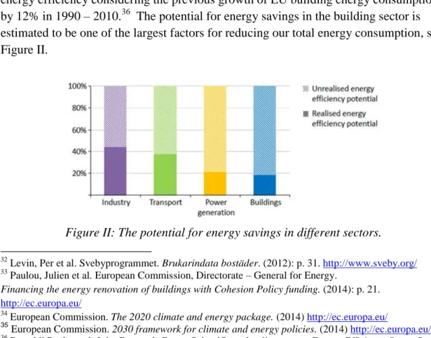
These targets are known as the “20-20-20” targets and are key objectives for the year 2020. In March 2014 a continuation on the 20-20-20 targets were made to the year 2030. Only the first two targets were given new specific goal values, reducing greenhouse gas emissions by 40% and increasing the share of renewable energy to at least 27%. The last goal regarding energy efficiency has not got a specific goal; the EU parliament has only stated that EU must continue to improve its energy efficiency.35 It is understandable that EU would not give specific new goals on the improvement energy efficiency considering the previous growth of EU building energy consumption by 12% in 1990 – 2010.36 The potential for energy savings in the building sector is estimated to be one of the largest factors for reducing our total energy consumption, see Figure II.
Figure II: The potential for energy savings in different sectors.
32 Levin, Per et al. Svebyprogrammet. Brukarindata bostäder. (2012): p. 31. http://www.sveby.org/ 33
Paulou, Julien et al. European Commission, Directorate – General for Energy.
Financing the energy renovation of buildings with Cohesion Policy funding. (2014): p. 21.
http://ec.europa.eu/
34 European Commission. The 2020 climate and energy package. (2014) http://ec.europa.eu/ 35
European Commission. 2030 framework for climate and energy policies. (2014) http://ec.europa.eu/
36 Bertoldi Paolo et al. Joint Research Centre Scientific and policy report. Energy Efficiency Status Report
13
To get an understanding of the building codes regarding building energy consumption in the industrialized world the current situation in the author’s home country Sweden will be reviewed. The reasoning behind this more specific location is the benchmarking difficulties imposed by the great regulation and climate variability in the EU as a whole. In 2011 the total Swedish national energy use reached approximated 337.5 TWh
accordingly to the Swedish energy agency. The household sector accounted for 86.3 TWh, which corresponds to 22.8 % of the total energy use.37 Two years earlier, in 2009, Statistics Sweden (SCB) made an evaluation on the average Swedish house energy consumption:38
Living area: 149
Total energy use: 23 980 kWh per year
Total energy use per area per year: 160.9 Swedish building codes2.2.1
Today the Swedish national board of housing, building and planning (Boverket) is responsible for the Swedish building codes for building energy use. As ordered by the Swedish government, they have come up with limitations for energy use such as space heating, domestic hot water heating and common electricity. The daily average
temperature in Sweden differs from the south to the north. In the northern town Kiruna the yearly mean temperature is -1.96°C and in the southern town Malmo the yearly mean temperature is +8.08°C.39 Since the mean temperature is this different the energy demand will also be different. To accommodate this variability Boverket divided Sweden into three different climate zones, see Figure III.40
Figure III: Swedish climate zones by Boverket.
37 Energimyndigheten. Total energianvändning – Total slutlig energianvändning i Sverige. Hushåll.
(2012) http://www.energimyndigheten.se/
38 Energimyndigheten. Ditt hus och din uppvärmning. (2012) http://www.energimyndigheten.se/ 39 World Meteorological Organization, World weather information service for Malmo and Kiruna,
http://www.worldweather.org/
40
14
The latest report from Boverket is BBR20 (Boverkets building regulations 20). The maximum energy use for residential buildings is defined in Table 1.
Table 1: Maximum allowed total energy use in residential buildings in Sweden. 41
Climate zone I Climate zone II Climate zone III
Max non electrically heated 130 110 90
Max electrically heated 95 75 55
In BBR20 the heated area, Atemp, is defined as the total internal floor area heated above 10°C.42 The Umean value must not exceed 0.4 for all climate zones.
Passive house
2.3
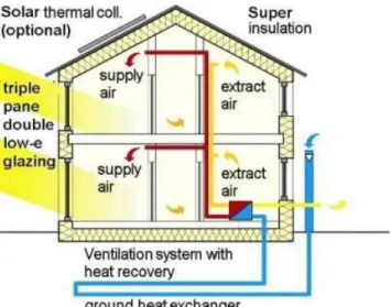
A passive house is a building with a primary goal to be energy efficient. The basic idea is to utilize a well-insulated, airtight building envelope with mechanical ventilation similar to a thermos. The passive houses are primarily heated by passive solar gain and by internal gains from people and activities inside the house, see Figure IV. It is a comprehensive system where “passive” refers to the opposite of “active” where heat sources like radiators are in use.43
Figure IV: Passive house thermal system
A Passive House is highly sustainable and uses up to 90% less energy than typical Central European buildings. The investment in higher quality building components can be compensated by the elimination of expensive heating and cooling systems and seen from the entire life cycle a passive house is cheaper than an ordinary building because
41 Boverkets författningssamling. BFS 2013:14 BBR 20. (2013): p. 37. https://rinfo.boverket.se/ 42 Boverket. Vad är Atemp för något? http://www.boverket.se/
43
15
of the low energy use during its operational phase. The construction of a passive house can be quite similar to that of an ordinary house and no special construction type is required.44,45
There are also other energy efficient standards similar to the passive houses. Some with even better energy classifications called zero-energy houses and plus-energy houses. These are houses that meet all requirements for a passive house and also have the sum of the delivered weighted energy to the building equal to the sum delivered from the building during one year. If the energy delivered to the building is less than the energy from the building it is a plus energy house.46
History of the passive house 2.3.1
The passive solar building design is not a new concept.47 The ancient Greeks and Chinese utilized this method thousands of years ago. But the modern idea of the passive house came from Professor Bo Adamson from the Department of Building Science at Lund University in the late 80s. By improving the building envelope and interchanging the space heating system to a passive solar system Adamson saw that a good “passive design” for a house also worked in cold climates, with no auxiliary heating or cooling. With help from his colleague Wolfgang Feist the full concept of passive houses was realized in 1988 and the first version was later built in Darmstadt Kranichstein,
Germany in 1990.48 The first international certified passive house in Sweden was built in 2008. Although other buildings should have been defined as passive houses a few years earlier but they did not get an international certification.49
The number of passive houses in the world has grown rapidly and proven to be a reliable system in many different climates. In 2013 it was estimated that there were 50.000 units built worldwide, most of them in Germany, Austria and Switzerland.50
Definition 2.3.2
A Passive House is not energy standard but a fundamental concept to reduce the
ecological footprint. The idea is to have a house use the least amount of energy and still have the highest level of comfort. The Passive House Institute has made the following definition of a Passive House: 51
44 Passive House Institute, International Passive House Association. The Passive House – comfortable,
affordable, sustainable. (2012) http://passivehouse-international.org
45
Passipedia. What is a Passive House? http://passipedia.passiv.de/
46Erlandsson, Martin et al. Sveriges Centrum för Nollenergihus. Kravspecifikation för nollenergihus,
passivhus och minienergihus FEBY. (2012): p. 4 http://www.nollhus.se/
47Passipedia. The Passive House – historical review. http://passipedia.passiv.de/
48 Feist, Wolfgang. Passive House Institute. 15th Anniversary of the Darmstadt – Kranichstein Passive
House. (2006) http://passivhaustagung.de/
49 Passipedia. Sweden’s first certified Passive House kindergarten. http://www.passipedia.org/ 50 Passive House Institute, International Passive House Association. The Passive House – comfortable,
affordable, sustainable. (2012) http://passivehouse-international.org
51
16
“A Passive House is a building, for which thermal comfort (ISO 7730) can be achieved solely by post-heating or post-cooling of the fresh air mass, which is required to achieve sufficient indoor air quality conditions – without the need for additional recirculation of air.”
The definition is valid for all climates and thermal comfort is achieved to a maximum extent through passive measures using insulation, heat recovery, passive use of solar energy and internal heat sources.52
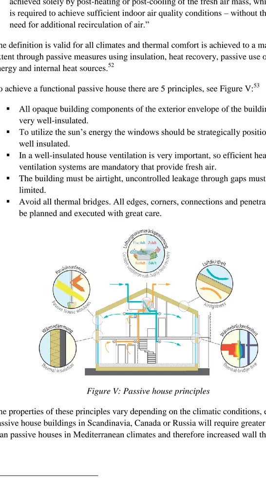
To achieve a functional passive house there are 5 principles, see Figure V:53
All opaque building components of the exterior envelope of the building must be very well-insulated.
To utilize the sun’s energy the windows should be strategically positioned and well insulated.
In a well-insulated house ventilation is very important, so efficient heat recovery ventilation systems are mandatory that provide fresh air.
The building must be airtight, uncontrolled leakage through gaps must be limited.
Avoid all thermal bridges. All edges, corners, connections and penetrations must be planned and executed with great care.
Figure V: Passive house principles
The properties of these principles vary depending on the climatic conditions, e.g.
passive house buildings in Scandinavia, Canada or Russia will require greater insulation than passive houses in Mediterranean climates and therefore increased wall thickness.
52 Passipedia. The Passive House – definition. http://passipedia.passiv.de/ 53
17
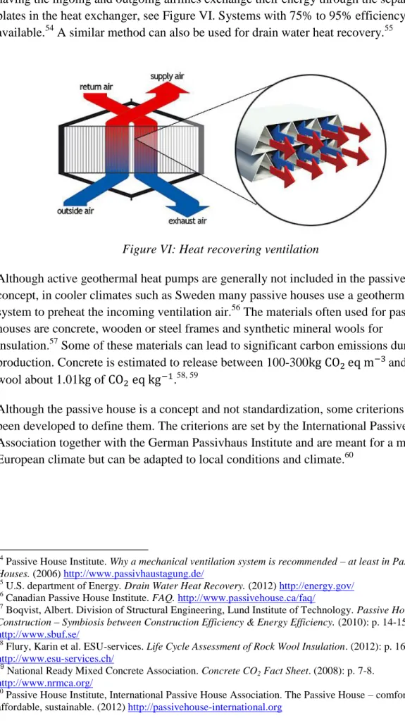
Heat recovery through ventilation is a key component of a passive house. It works by having the ingoing and outgoing airlines exchange their energy through the separating plates in the heat exchanger, see Figure VI. Systems with 75% to 95% efficiency (η) are available.54 A similar method can also be used for drain water heat recovery.55
Figure VI: Heat recovering ventilation
Although active geothermal heat pumps are generally not included in the passive house concept, in cooler climates such as Sweden many passive houses use a geothermal system to preheat the incoming ventilation air.56 The materials often used for passive houses are concrete, wooden or steel frames and synthetic mineral wools for
insulation.57Some of these materials can lead to significant carbon emissions during production. Concrete is estimated to release between 100-300 and rock wool about 1.01 of .58, 59
Although the passive house is a concept and not standardization, some criterions have been developed to define them. The criterions are set by the International Passive House Association together with the German Passivhaus Institute and are meant for a mid-European climate but can be adapted to local conditions and climate.60
54
Passive House Institute. Why a mechanical ventilation system is recommended – at least in Passive
Houses. (2006) http://www.passivhaustagung.de/
55 U.S. department of Energy. Drain Water Heat Recovery. (2012) http://energy.gov/ 56 Canadian Passive House Institute. FAQ. http://www.passivehouse.ca/faq/
57
Boqvist, Albert. Division of Structural Engineering, Lund Institute of Technology. Passive House
Construction – Symbiosis between Construction Efficiency & Energy Efficiency. (2010): p. 14-15.
http://www.sbuf.se/
58 Flury, Karin et al. ESU-services. Life Cycle Assessment of Rock Wool Insulation. (2012): p. 16.
http://www.esu-services.ch/
59
National Ready Mixed Concrete Association. Concrete CO2 Fact Sheet. (2008): p. 7-8. http://www.nrmca.org/
60 Passive House Institute, International Passive House Association. The Passive House – comfortable,
18 Certification specification. 2.3.3
The Passive house demands have been adjusted from mid-European climate to suit the Swedish climate conditions by SCNH (Sveriges Centrum för Nollenergihus) from an earlier expert group appointed by FEBY (Forum för Energieffektiva Byggnader). Their newest specific criteria is from 2012, called FEBY12. A passive house in Sweden must not only follow the FEBY12 but also the Swedish National Board of Housing building regulations (BBR20).61
Below are the requirements for a building to be considered a passive house in Sweden, mid-Europe and Mediterranean when the minimum indoor temperature is set to 21 degrees. To meet the requirements for passive houses, you must either meet the heat load or heat demand criteria. All the requirements for Sweden are taken from
FEBY12.62
Energy demand and peak load for space heating (heating load):
The German Passive House Institute illustrates the heating load with following
calculations and assumptions. The supply air must be heated, but only to 51°C to avoid scorching of the dust. To ensure a good indoor air quality the ventilation system must deliver 30 of fresh air per person. Air has the specific heat capacity of
1.01 and density of 1.2 at ca. 21°C. This is equivalent to
0.33 . Then the power demanded can be calculated according to Equation 10.
Assuming that one person takes up 30 of living area the maximum heating load at a given point may not exceed 10 according to Equation 11.
This limit works as a starting point all around the world for energy demand for passive houses since the calculations is independent of climate and temperature, so a passive house will require different levels of insulation depending on climate zone in order to meet this criterion.63
But the world is not as perfect as a mathematical formula and in Sweden the peak-heating load is regulated by SCNH and it follows the three climate zones set up by Boverket, see Figure III. The peak load for space heating, , for residential buildings may be higher as the average temperature drops, see Table 2.
61 Sveriges Centrum för Nollenergihus. Om FEBY12. (2012) http://www.nollhus.se/ 62
Ibid, Kravspecifikation för nollenergihus , passivhus och minienergihus, (2012)
63
19
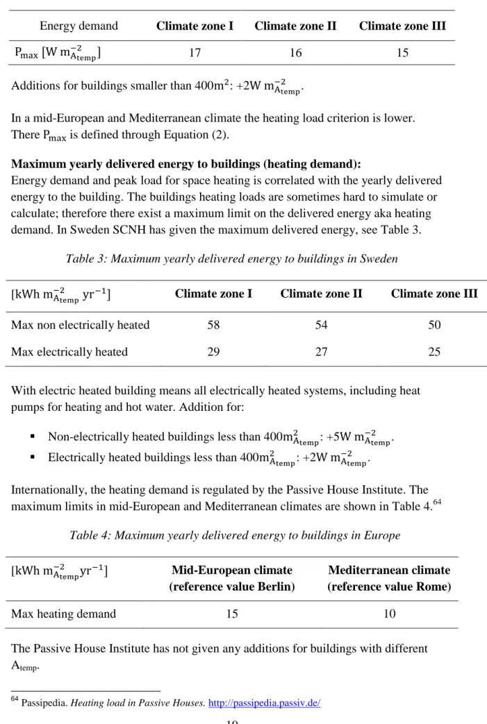
Table 2: Limit peak load for space heating for passive house in Sweden.
Energy demand Climate zone I Climate zone II Climate zone III [
]
17 16 15
Additions for buildings smaller than 400 : +2 .
In a mid-European and Mediterranean climate the heating load criterion is lower. There is defined through Equation (2).
Maximum yearly delivered energy to buildings (heating demand):
Energy demand and peak load for space heating is correlated with the yearly delivered energy to the building. The buildings heating loads are sometimes hard to simulate or calculate; therefore there exist a maximum limit on the delivered energy aka heating demand. In Sweden SCNH has given the maximum delivered energy, see Table 3.
Table 3: Maximum yearly delivered energy to buildings in Sweden
[ ] Climate zone I Climate zone II Climate zone III
Max non electrically heated 58 54 50
Max electrically heated 29 27 25
With electric heated building means all electrically heated systems, including heat pumps for heating and hot water. Addition for:
Non-electrically heated buildings less than 400 : +5 . Electrically heated buildings less than 400 : +2 .
Internationally, the heating demand is regulated by the Passive House Institute. The maximum limits in mid-European and Mediterranean climates are shown in Table 4.64
Table 4: Maximum yearly delivered energy to buildings in Europe
[ ] Mid-European climate (reference value Berlin)
Mediterranean climate (reference value Rome)
Max heating demand 15 10
The Passive House Institute has not given any additions for buildings with different Atemp.
64
20
Hemp
2.4
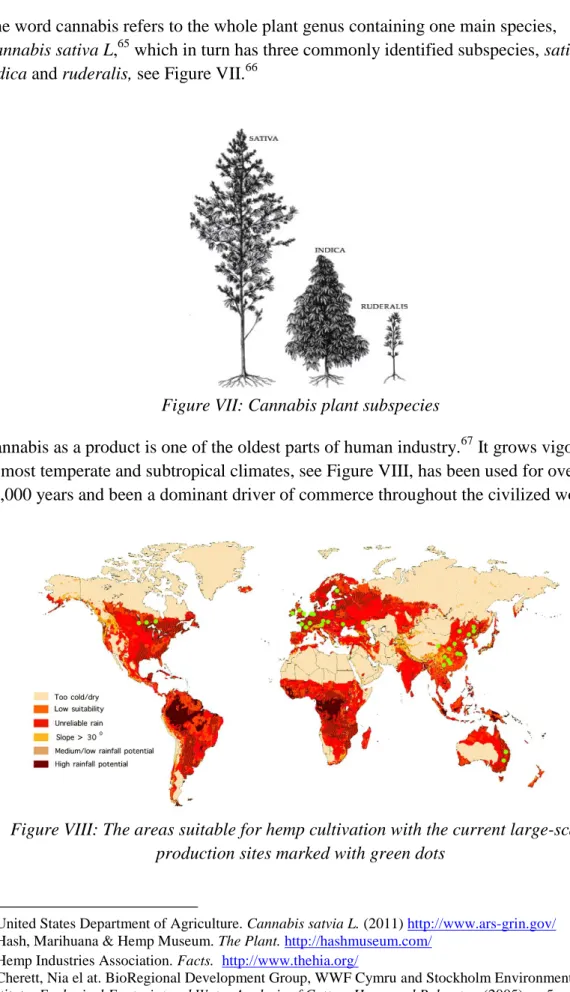
The word cannabis refers to the whole plant genus containing one main species,
Cannabis sativa L,65 which in turn has three commonly identified subspecies, sativa,
indica and ruderalis, see Figure VII.66
Figure VII: Cannabis plant subspecies
Cannabis as a product is one of the oldest parts of human industry.67 It grows vigorously in most temperate and subtropical climates, see Figure VIII, has been used for over 10,000 years and been a dominant driver of commerce throughout the civilized world.68
Figure VIII: The areas suitable for hemp cultivation with the current large-scale production sites marked with green dots
65 United States Department of Agriculture. Cannabis satvia L. (2011) http://www.ars-grin.gov/ 66 Hash, Marihuana & Hemp Museum. The Plant. http://hashmuseum.com/
67 Hemp Industries Association. Facts. http://www.thehia.org/
68 Cherett, Nia el at. BioRegional Development Group, WWF Cymru and Stockholm Environment
Institute. Ecological Footprint and Water Analysis of Cotton, Hemp and Polyester. (2005): p. 5.
21
In 1938 it was estimated in the US that it existed over 25 000 industrial uses for the plant and that is about to become the new billion-dollar crop. However legislative action against the plants propagation was already in action and later spread to most of the world.69 One milestone treaty with global reach was the UN Single Convention on Narcotic Drugs in 1961.70
Hemp, although technically a synonym for cannabis, commonly refers to the industrial varieties of the plant.71 The cultivation of these specific breeds have now been approved in the EU, similar to most of the industrialized world, so long as they contain less than 0.2 % of the psychoactive substance THC.72 These small amounts makes any sensation of a high impossible.73
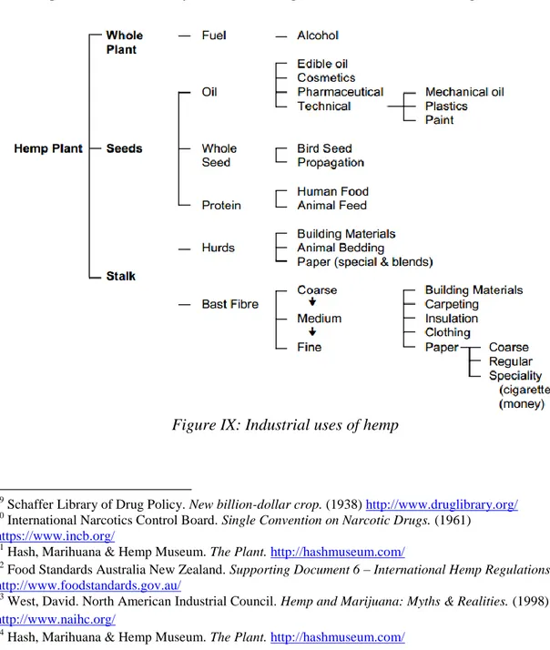
Nearly all hemp grown for industrial purposes is from the subspecies Cannabis Sativa. As it is the tallest variety, it also produces the longest stalks and therefore has the greatest production efficiency and widest range of industrial uses, see Figure IX.74
Figure IX: Industrial uses of hemp
69 Schaffer Library of Drug Policy. New billion-dollar crop. (1938) http://www.druglibrary.org/ 70 International Narcotics Control Board. Single Convention on Narcotic Drugs. (1961)
https://www.incb.org/
71 Hash, Marihuana & Hemp Museum. The Plant. http://hashmuseum.com/ 72
Food Standards Australia New Zealand. Supporting Document 6 – International Hemp Regulations.
http://www.foodstandards.gov.au/
73 West, David. North American Industrial Council. Hemp and Marijuana: Myths & Realities. (1998)
http://www.naihc.org/
74
22
Depending on the use, hemp will be grown in different ways. The growth cycle is 70 to 140 days and from one hectare you can get an average of 800 of gain, which is equivalent to 200 litres of hemp-oil and 600 of meal. The same hectare yields 6 tons of straw which is approximately equivalent to 1.5 tons of hemp fibre.75 The more densely hemp is planted the finer the stems get and the growth is simultaneously stimulated at the same time due to competition of sunlight. The growth rate can reach speeds of up to 100-300 mm per week.76 Hemp does not demand special herbicides because other plants cannot keep up with hemps growth rate and the canopies block the sun light making hemp to a natural weed suppressor.77 The shading from the canopies also helps to protect the soil from dehydration and the soil is held together as well as aerated by the roots after harvest.78 Also up to 70 % of the nutrients used during the growing process are returned to the soil through fallen leaves, roots, retting and harvest trimmings.79
Because of these crop attributes, hemp can often be grown without herbicides, fungicides or other pesticides with minimal nutrient additives.80 It is also more than twice as productive and about three times less water intensive than cotton.81
Hemp building materials 2.4.1
Hempcrete is bio-composite building material developed in the 1980s82 consisting of hemp shives (the chopped stem core) and lime-based binder mixed with water. It's consistency and application is similar to concrete, although it's less runny it is usually applied as a mass in between shuttering, surrounding a structural timber frame. After a short drying period the shuttering is then removed leaving a massive wall, which can then be rendered or plastered. This whole procedure is illustrated in Appendix C. The monolith application style and the similarity between timber and hempcrete thermal properties also make the system less prone to causing thermal bridges.83
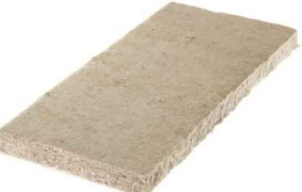
However there are also alternative application techniques with different types of prefabricated bricks84, see Figure X, and boards as well as spray application which are more common when used in renovation projects.85Another interesting development is the introduction of carbon negative hemp fibre insulation with a low conductivity
75
Agriculture and Agri-Food Canada. Industrial Hemp. (2013) http://www.agr.gc.ca/
76 Allin, Steve. Building with Hemp. (2012): p. 23
77 Hemp Industries Association. Facts. http://www.thehia.org/ 78 Allin, Steve. Building with Hemp. (2012): p. 27
79 British Columbia Ministry of Agriculture and Food. Industrial Hemp. (1999) http://www.agf.gov.bc.ca/ 80
Hemp Industries Association. Facts. http://www.thehia.org/
81 Cherett, Nia el at. BioRegional Development Group, WWF Cymru and Stockholm Environment
Institute. Ecological Footprint and Water Analysis of Cotton, Hemp and Polyester. (2005): p. 16 – 21
http://www.sei-international.org/
82
Allin, Steve. Building with Hemp. (2012): p. 34
83 American Lime Technology. The Thermal Performace of Tradical® Hemcrete®. (2006): p. 8
http://americanlimetechnology.com/
84 Cannabric. Catalogue. http://www.cannabric.com/ 85
23
similar to traditional mineral wools that could be adopted into the building system where the climate is colder and greater insulation is required, see Figure X.86
Figure X: (a) Picture of a cannabric, (b) picture of hemp isolation
The binder constituents and proportions of different types of limes may vary as well as the inclusion of cement and other additives.87
There are also different mixing proportions and compactness’s adjusted for the different properties preferred in different parts of the building. The main difference between the mixes is the balance between structural strength and insulation. For example the amount of binder is generally increased to about 25% of the mix volume to make the walls stronger, while maintained at a lower 10% for less rigid, more insulating roof fillings.88 To understand how the mix gets its strength and "sets" it is necessary to understand the basics of the lime cycle.
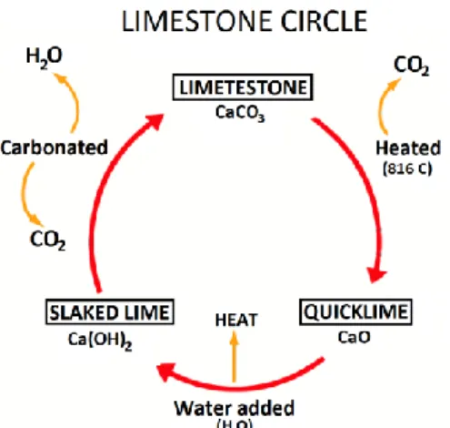
The limestone cycle 2.4.2
Limestone is created when particles of shells, bones or coral deposited on the sea bed for about a million years get pressured into carbonate rock, . Some of these limestone quarries also contain impurities that allow the final product called hydraulic lime to set underwater, or in humid walls. The quarries are mined and the material is burned, releasing to create quicklime, . Water is then added to create slaked lime, , during an exothermic process. If the final product is dry it is called hydrated lime which together with hydraulic lime is the two main components of the hempcrete binder. The slaked lime then reabsorbs the same amount of it one released in the atmosphere and starts to harden and return to its initial form. This
86
Zampori, Luca et al. ACS Publications Environmental Science & Technology. Life Cycle Assessment of
Hemp Cultivation and Use of Hemp-Based Thermal Insulator Materials in Buildings. (2013)
http://pubs.acs.org/doi/
87 Allin, Steve. Building with Hemp. (2012): p. 41 88
24
reabsorption of is also why lime has a low greenhouse gas emission and thus low global warming impact89, see Figure XI.
Figure XI: Lime cycle
Hempcrete technical properties 2.4.3
The estimated values for a standard mix of the common tradical hempcrete mix, called hemcrete®, can be seen in Table 5. Some values are given an interval depending on the relative humidity in the material and density, which will be discussed further in the hempcrete building system section. In addition to the monolith mass the building often gets finished with hemp plaster which properties can be found in Table 6. The values from Table 5 and 6 are later used to in the model for simulations.
Table 5: Properties of hempcrete at ρ=275 .90
Density (ρ) 275 Flexural strength 0.3-0.4 Thermal conductivity at 10 C (λ) 0.06 Heat Capacity (c) 1500-1800 Thermal diffusivity (α) ~1.4 Fire Rating 1 h BS EN 1365-1:1999 Carbon capture 130 Airtightness (q50)
89 Allin, Steve. Building with Hemp. (2012): p. 38 ff. 90
25
Table 6: Properties of hemp plaster91, 92
Density (ρ) 700 to 950
Thermal conductivity at 10 C (λ) 0.12-0.13 Heat Capacity (c) 1378-1871
These properties of hempcrete lead to some material attributes that can be summarized according to the following:
High thermal inertia93 High thermal insulation94 High sound insulation95
Medium density and high thermal capacity96
Breathable nature, and ability to act as moisture buffer97 Nature of application minimises thermal bridges98 Low effusivity that can improve thermal comfort99 Inherently airtight structures100
Fire and pest resistant101
Can significantly reduce emissions102 Low waste103
Competitive economic104 Easily recyclable105
The hempcrete building system interaction 2.4.4
The hempcrete building system works with a different logic than most common passive houses. Instead of using an insulating envelope that does not transfer moisture vapour, the material is breathable. This is not to be confused with air permeability which is relatively low in hempcrete. This vapour permeability of hempcrete means the thermal properties vary with the relative humidity of the atmosphere. It also utilizes higher
91 Lhoist UK. Tradical Building lime innovation. Renders/plasters. http://www.tradical.com/ 92
Allin, Steve. Building with Hemp. (2012): p. 60
93 Mawditt, Ian. Living Space Sciences. Unique thermal performance of Tradical Hemcrete. (2008): p.
16. http://www.limetech.info/
94 Tradical. Hemp Lime Technology. Tradical Information Pack. p. 3. http://www.lhoist.co.uk/
95 Ibid p. 3. 96 Ibid p. 12 ff. 97 Ibid p. 47. 98 Ibid p. 47. 99 Ibid p. 47. 100 Ibid p. 47. 101 Ibid p. 3 102 Ibid p. 3 103 Ibid p. 3 104 Ibid p. 15 105
26
levels of thermal capacity and inertia than the average passive house. To complicate things further the mix ingredients, the proportions used and the application technique also play an important role in the thermal performance. Several studies have been released on how some of these parameters affect the thermal performance of hempcrete. In the following an overview of these results will be illustrated to give a better
understanding of the system and its potential.
The thermal conductivity and U value are mainly related to the density of the mix as shown in Figure XII.106
Figure XII: Hemcrete® U values for different mixes
The density is in turn affected by the amount of humidity trapped in the walls as well as how hard hempcrete is packed during construction. It would appear that a high relative humidity, an increase in density, would also lead to increased heat fluxes through the wall. However due to hempcretes breathability and voluminous moisture handling the effects of latent heating has to be taken into account as well. Hemp has also been found to have an unusual porous system that contributes to these latent heating effects.107 Recently some studies have shown remarkable results indicating that the heat flux may actually decrease when relative humidities are increased. However these tests were not able to confirm how much of the heat flux suppression that was actually caused by latent heating. Research on hemps phase changing properties is ongoing.108 Figure XIII
106
Lime Technology. Tradical® Hemcrete® Thermal Performance. (2006): p. 7
http://www.limetechnology.co.uk/
107 Simpson, Scott. University of East London. An investigation of hygrothermal properties of lime-hemp
and clay-hemp blocks retrofitted onto light-timber frames. (2004): p. 62
108 Ibid p. 137 200 250 300 350 400 500 330kg/m3 0,345 0,276 0,23 0,197 0,173 0,153 275kg/m3 0,3 0,24 0,2 0,171 0,15 0,133 220kg/m3 0,25 0,2 0,167 0,143 0,125 0,111 0,1 0,15 0,2 0,25 0,3 0,35 U-value Hempcrete thickness (mm)
27
shows a summary for the volumetric heat capacity for some different building materials as well how hempcrete is affected by a change relative.
Figure XIII: A comparison of volumetric heat capacity for hemp and other common building materials.
A high thermal capacity and a low conductivity lead to a low thermal diffusivity which is why hempcrete has a high thermal inertia.109 The effusivity is also relatively low, which means heat has a hard time getting into the material through its surface.110 This also contributes to the feeling of comforting warmth when in proximity to the walls. Hempcrete with its good thermal and moisture buffers effectively stabilize the indoor temperature as well as relative air humidity leading to lower overall heat fluxes and a healthier and safer indoor environment (see Figure XIV).111 Under a dynamic load the Hempcrete heat flux can even become lower than mineral wool despite mineral wool having a much better insulation value.112 These delays of heating and cooling transfer can also help optimize the latent energy effects to help cooling during the day and heating at night.113
109 Lime Technology. Tradical® Hemcrete® Thermal Performance. (2006): p. 8
http://www.limetechnology.co.uk/
110 Simpson, Scott. University of East London. An investigation of hygrothermal properties of lime-hemp
and clay-hemp blocks retrofitted onto light-timber frames. (2004): p. 44
111
Lime Technology. Tradical® Hemcrete® Thermal Performance. (2006): p. 10 ff.
http://www.limetechnology.co.uk/
112 Ibid p. 12
113 Simpson, Scott. University of East London. An investigation of hygrothermal properties of lime-hemp
and clay-hemp blocks retrofitted onto light-timber frames. (2004). p. 61
4190 3510 2000 1875 1800 1360 1120 800 561 550 512 88 46 41 22 12 1 0 500 1000 1500 2000 2500 3000 3500 4000 4500 water @ 10°C Mild steel Cast conctrete Glass Dense conctrete block Brick Wood (hard) Wood (soft) Hempcete @ 65%RH Areated block Hempcrete dry Foamed glass Mineral wool slabs PIR EPS Mineral wool rool Air
Volumetric heat capacity (KJ m^-3 K^-1)
Insulation products
28
Figure XIV: Dampened and delayed interior temperatures (red) relative to exterior temperatures (purple) in a light timber framed building with lime-hemp
From these results we can see that the traditional U values alone only express part of a material's thermal performance ability. Other factors such as thermal storage, thermal inertia, hygroscopicity and moisture storage can all help reduce heating, cooling and ventilation energy demands. These properties also contribute to a comfortable and healthy living environment for occupants by attenuating temperature and relative humidity fluctuations.114
114 Simpson, Scott. University of East London. An investigation of hygrothermal properties of lime-hemp
29
Method
3.
To estimate and compare the energy use of different buildings in different climates the dynamic simulation program VIP-energy v2.1.1 was used. The software is created by StruSoft AB which is a Swedish software manufacturer specialized in software
applications for the building industry. The program uses dynamic calculation methods to calculate the energy use per hour for a specific building over a given time period. VIP-energy is validated by IEA-BESTEST, ASHRAE-BESTEST, CEN-15265 and 20 years of research and practical work.115
Input
3.1
The base of the modelling process was an example house model from VIP’s own website.116 Since it was a modern one family house (see Figure XV and Figure XVI) built with common passive house materials and a regular structure it was considered suitable as a benchmark to evaluate the hempcrete building systems potential. To create the second model most of the materials in the house were then replaced to simulate a traditional hemp house while leaving the dimensions unchanged. These two models’ wall thicknesses were then modified as well as relocated to different parts of the world to allow for a comparative study of both building techniques and their performance in different climates. A thorough presentation of the input variables is listed in Appendix A. This section however will feature a brief overview of the different models used to discuss the motivations behind their design.
Figure XV: Model building layout design
115 Structural Design Software in Europe AB. VIP-Energy. http://www.strusoft.com/ 116
30
Figure XVI: Model building facades
Heat recovery, temperatures and location 3.1.1
Initially the example house model was adjusted to compatibility with passive house norms and updated to modern standards. This was done primarily by setting the ventilations air flow to 0.35 to satisfy the BBR20 codes117
. Because systems with a ventilation heat recovery of η = [75%,95%] were available the model got the mean value, η =85%, for both in- and outgoing air flow. A drain line heat recovery was chosen with η =50%118 and a geothermal heat pump were also added to the model. Although such heat pumps are generally not included in the passive house concept we used it as a more sophisticated solution to make up for VIP’s limitations of geothermal preheating systems of the incoming ventilation air. Using a geothermal heat pump has also been done before in Swedish passive houses.119
The minimum indoor temperature was set to 21°C and the maximum to 27°C to meet the BBR20 code for measuring energy use.
The locations of the two houses were first set to three different Swedish cities, Malmo, Sundsvall and Kiruna, one from each climate zone as defined in Figure III. This simplified the comparison between the models’ performances and passive house criteria, which is otherwise vaguely defined in the EU as a whole with its widely differing climates. Afterwards the building models were moved to Berlin and Rome to give an understanding of the potential of hempcrete houses in central Europe as well as around the Mediterranean. The different locations are shown in Figure XVII.
117
Boverkets byggregler, BBR. Del 2 Regelsamling för byggande. 6 Hygien, hälsa och miljö. (2012): p. 217 ff. http://www.boverket.se/
118
Enviromental Building News, Recovering Heat from Wastewater (1997), http://buildinggreen.com
119
Thelin, Björn. Ekofektiv. Advanced BTES solution for passive house in Haninge. (2011)
http://ekofektiv.com/
Façade facing south Façade facing east
31
Figure XVII: Map of the locations for the simulations
Building envelope 3.1.2
The building in the example house model was first simplified by the removal of a cellar
which led to recalculations of the floor as well as inner walls area to 136.7 . Then the
walls and their 2D connection parts were all adjusted to a thickness of 200, 300 and 400 mm respectively in different versions of the model to study the impact on thermal performance. The windows and doors were adjusted to clear passive house
recommendations with a U-value of 0.80.120 The window solar transmission values were derived from an existing product with a glass U-value set to 0.70 compensating for the total U-value increase after installation of the full window unit.121
The hempcrete model was then adjusted to the same dimensions leaving windows, doors and all gravel material as well as the wooden interior for the roof and floor
unchanged. The other materials however were replaced with different density hempcrete mixes for roof (225 ), walls (275 ) and floor (325 ), the latter
120 International Passive House Association. Passive House Guidelines.
http://www.passivehouse-international.org/
121 Feist, Wolfgang. Passive House Institute. Window – Heat Transfer Coefficient U
w and Glazing – Heat
32
coated with hemp plaster according to described situations of use122. We also used the same plaster as rendering for the external parts of the wall although this is slightly less common123. The different mix densities and conductivities used in the model were derived from Figure XII.
Different density mixtures have different specific heat capacities. In Figure XIII the volumetric heat capacity is shown to be 512 for dry hemp and by using different hemp densities in the wall were given a natural improved U-value and better insulation while still utilizing the heat capacity. The different densities for the wall were chosen to ρ=225 , 275 and 330 and the hemp plaster were chosen to ρ=700 . The different specific heat capacities for the walls are shown in Table 7 and could be calculated by using Equation 4 and for plaster using Table 6.
Table 7: The relationship between density and specific heat capacity
Density (ρ) 225 275 330 700 Heat capacity (c) 2275.5 1861,8 1551,5 1871
In reality embedded timber frames are also required to maintain the hempcrete building structure. This as well as the practical difficulty to produce perfect mix compactness has been included in the model through a slightly higher adjusting ΔU-value set to 0.02, despite the building system giving little room for thermal bridges. A comparative study from Limetech reviewing a timber frames impact on the walls combined thermal performance was also considered.124
Time schedule and operating case 3.1.3
The time schedule and internal operation and generation of heat and moisture is
adjusted to the SVEBY (Standardisera och verifiera energiprestanda i byggnader) from the Swedish Energy Agency. Table 8 shows the calculated time schedule and operating cases, SVEBY model is shown in Appendix B.
122
Allin, Steve. Building with Hemp. (2012): p 45
123
Ibid, p 103
124 Mawditt, Ian. Living Space Sciences. Unique thermal performance of Tradical Hemcrete. (2008): s 6
33
Table 8: Time schedule and operating case
Time period Activity energy: To room air [ ] Activity energy: External [ ] Personal energy [ ] Hot water [ ] Room temperature [°C] 00:00-06:00 1.49 0.64 2.05 1.85 21-27 06:00-07:00 2.26 0.97 2.05 2.81 21-27 07:00-17:00 2.26 0.64 0 2.81 21-27 17:00-18:00 2.26 0.64 2.05 2.81 21-27 18:00-24:00 4.52 1.94 2.05 5.61 21-27
34
Results
4.
This section covers the simulation results. The main focus is to illustrate the energy performance of the two building concepts.
Energy balance
4.1
The energy balance from the simulations of the 40 cm passive and hempcrete house is shown below. The 40 cm wall model results can be considered most interesting since they represent a more realistic passive house wall width and therefore also give a more realistic demonstration of the potential of both building concepts. Figure XVIII show the simulations of the passive house in all locations and Figure XIX show the
simulations for the hempcrete house.
35
The graphs show that the houses behave similarly at the different locations. In the supplied energy area one can see that the passive solar gain increases when the houses are moved further south while passive cooling increases to eliminate the excess heat during the summer months.