KALMAR, SWEDEN, November 25-27, 2003
EXPERMENTALPLANTFORTHE
LEACHATE TREATMENT AT KAUNAS
LANDFILL, LITHUANIA
Mindaugas Rimeika Vilnius Gediminas Technical University, Lithuania Vilmante Karlaviciene Vilnius Gediminas Technical University, Lithuania/ Kalmar University, Sweden Jurgita iimanciute Vilnius Gediminas Technical University, LithuaniaABSTRACT
Landfills make a negative impact on the environment all over the world, especially if they are constructed and operated in nonconformity to the environment requirements. There are about eight hundred registered dumping sites in Lithuania, but just a few of them have been constructed according to the requirements and only one landfill has leachate treatment plant. Only a few decades ago first attempts for introduction of environmental care instruments for landfill and leachate handling were made. Therefore, leachate treatment methods and technologies are still under development and have not been completely settled. This article presents overview of leachate treatment technology applied in the Lapes Landfill (Lithuania, Kaunas). The overall situation in the Lapes Landfill, concerning the volumes of collected waste and leachate quality has been presented. Lapes Landfill is second largest landfill in Lithuania and the first where leachate treatment plant has been constructed across the country. The heart of constructed treatment plants is aerobic reactor. The article presents review of the plants treatment efficiency and as well the main problems. The pilot plant testing of leachate treatment at Lapes Landfill has been carried out. Suggested leachate treatment technology is presented.
KEYWORDS
Landfill, leachate, treatment plant, aerobic and anaerobic reactors, settling tank, pond with sloped biofilters.
Bioremediation and Leachate Treatment KALMAR, SWEDEN, November 25-27, 2003
1 INTRODUCTION
There are about eight hundred dumping sites and polluted territories registered in the Lithuania. About 260 are formally functioning as landfills, of which 11 serve large cities, 70 are used by district centers and 180 used by villages. About 680 landfills are small, up to I hectare area, domestic waste dumps, 120 medium sized waste dumps ( from I to 5 hectare) and 35 large landfills (more that 5 ha). About one hundred important landfills have introduced groundwater and leachate quality monitoring system. All other polluted areas are left without any continuously local authority control. Most of landfill has little consideration for the environmental impact. Political decision has been made to close down or replace all old landfill by modern landfills by 2009. The ten large regional landfills will be constructed and they will cover all country needs. However, after closure of old landfills they will be as a hot spot to environment and measure for emissions reduction shall be implemented.
About 110000 tons of hazardous waste are accumulating in Lithuania annually. Destination point of biggest part of hazardous waste is landfills. Therefore, a negative landfills influence to the environment, such as groundwater and surface water pollution, gas generation, odor problem and others has been quickly observed.
Another important problem is soil contamination caused by biogenic and toxic materials, a result of agricultural activities. Former Soviet military activities have also left 67762 hectares, or about I % of Lithuania's territory, contaminated. More than 50 percent of former military camps land is contaminated by oil products and heavy metals. In places where pollution has reached greater proportions, damage has resulted not only in the aeration zone but in the groundwater as well.
Particularly little attention has been addressed to the collection and treatment of landfill leachate. Leachate from biggest landfills is collected in ponds, and then by pumps ( or vehicles) is recirculated to the top of landfill. Discharged water is penetrating to landfill and collecting to pond once again. Smaller landfills has none leachate collection system and leachate entering to environment uncontrolled. However, such leachate management system did not help much because Lithuania is located in a positive moisture balance zone and evaporation is much lower then precipitation. So landfill's body is saturated, the volume of recirculated leachate rapidly increase and that cause serious problems. Another ineffective solution is collection of stormwater (from surrounding areas) and leachate to the one accumulation pond. In this case, relatively clean stormwater is polluted by leachate and thereby volume of leachate is increased. For the treatment of these two types oflandfill's wastewaters a different treatment methods must be applied.
KALMAR, SWEDEN, November 25-27, 2003
2 GENERAL INFORMATION ABOUT THE LAPES LANDFILL IN KAUNAS Household and industrial waste from Kaunas City is presently disposed at Lapes Landfill situated approximately 13 km north - east the city center and in operation since 1973. Landfill serves more than 600 000 population. The landfill is set up in a natural hollow. The whole area of landfill takes 38. 7 ha. Household waste takes up the area of only 12.5 ha The average height of waste hill is 20 m. After thirty-year exploitation, about 2.5 min. me3 of waste is already collected. Every year the landfills increase by 100-130 thousand
tons of waste. But only about 1-2 % of collected and transported waste to landfill is recycled (see figure 1).
140000 12<XXXJ l<XXXlO I ■ Collected waste I ■ Recycled waste � S<XXXJ
.,,,
60'.XX) 40000 2<XXXJ 0 1995 I 996 I 997 1998 1999 2<XXl 200 I 2002Figure 1. Volume of collected and recycled waste
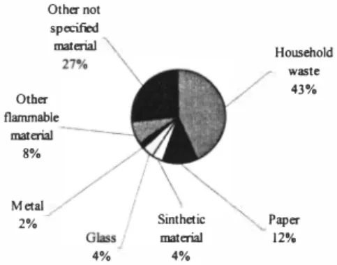
Typical composition of waste is presented in figure 2. Household waste (organic), paper, cardboard, plastic and other flammable materials dominate there.
Othe,not specified material Household Other flammable material 8% Metal 2% Sinthetic material waste 43% Paper 121', 4% 4%
Bioremediation and Leachate Treatment
KALMAR, SWEDEN, November 25-27, 2003
The landfill location has not been based on field investigation and the landfill is not equipped with a bottom liner or drainage system for the collection of leachate. The analysis of the under laying groundwater shows that the surrounding area is contaminated due to the leaking of leachate from the landfill. Calculated volume of average daily
leachate production is about 300 m3/d. However, only one third of leachate volume
(a proximately 70-100 m3/d) is collected and diverted to treatment. About 27 000
p
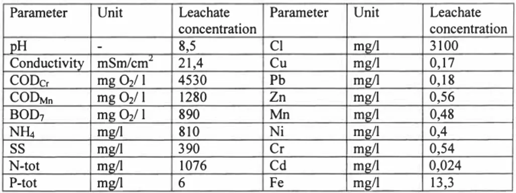
m /year of leachate, partly pretreated is entering the groundwater or open streams. Groundwater level vary from 0,5 m to 12,0 m from ground surface. Water table inside the landfill is about 12 m depth form waste surface at the landfill area. From an environmental point of view the main problem is the great amount of leachate penetrating the surroundings. Average leachate quality flowing to treatment plant is presented in table l. Calculated pollution load to environment from landfill is about l 000OPE. The main pollutants of leachate are organic, nutrients (nitrogen and phosphorus), metals (lead, iron, manganese, nickel, chromium, cadmium) and suspended solids, COD, BOD.
Table 1. Average leachate quality at Lapes Landfill
Parameter Unit Leachate Parameter Unit Leachate
concentration concentration
pH
-
8,5 Cl mg/I 3100Conductivity mSm/cmL 21,4 Cu mg/I 0,17
CODc, mg O2/ I 4530 Pb mg/I 0,18
CO�n mg 02/ I 1280 Zn mg/I 0,56
BOD1 mg 02/ I 890 Mn mg/I 0,48
NHi mg/I 810 Ni mg/I 0,4
ss
mg/I 390 Cr mg/I 0,54N-tot mg/I 1076 Cd mg/I 0,024
P-tot mg/I 6 Fe mg/I 13,3
Inside the landfill leachate the temperature reaches 30-40 °C degrees, oxygen is almost depleted, the gas pressure 20-30 mbars. Methane produces because of biodegradation of organics. According to preliminary investigations it is possible to extract about 990 Nm3/h of landfill gas with on average 57% concentration of methane. Extracted volume is far too big for local use, therefore plans for exporting of gas is under investigation. 3 EXISTING LEA CHA TE TREATMENT PLANT
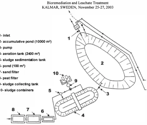
The first landfill leachate treatment plants in Lithuania have been constructed in the Lapes Landfill. Basic design of the leachate treatment plants has been made by Danish company COWiconsult. The plant has been put into operation in 1999, construction cost about 600000 EUR. The plants consist of a accumulating and settling ponds, aeration tank and tertiary treatment at sand and peat filters. Only one third ofleachate is coming to treatment plant, the rest flowing directly to stream or infiltrating into the soil. The
treatment plant is designed for a capacity of 80 m3/d. General layout of the plant is
KALMAR, SWEDEN, November 25-27, 2003 I.; 1- Inlet 2- accumulative pond (10000 m3) 3-pump 4- aeration tank (2400 m3)
5- sludge sedimentation tank 6- pond (100 m3)
7-sand filter 8- peat filter
9- sludge collecting tank 10- sludge containers
Figure 3. Leachate treatment plant at Lapes Landfill, Kaunas
Construction of activated sludge plant consist of the following construction:
• Leachate from the landfill is collected in the pond. The pond needs a volume of
approx. 1000 m3 to equalize the variation of leachate during the year and over the
lifetime of the landfill.
• A process tank with a approximately 2000 m3 equipped with mixers and aerators. In the process tank, microorganisms are suspended. These microorganisms degrade the organics and if not inhibited oxidize the ammonia to nitrite. It is necessary to add some phosphor as nutrient for the microorganisms. Designed sludge age is 25-30 days.
• A secondary sedimentation tank with a diameter of approximately 3 m. The secondary sedimentation tank is equipped with an effluent weir. In the secondary sedimentation tank the organisms settle down and the treated water flows over the effluent weirs.
• A pumping station with sludge pumps to return the settled sludge into the process tank for reuse. In this pumping station a surplus sludge pumps is also installed.
• A concentration tank (thickener) with diameter of approx. 4 m. The concentration tank is equipped with an effluent weir and pump for the pumping of concentrated sludge. The concentrated sludge is pumped to containers and afterwards transported for disposal at the landfill.
0,4 57
15 mg/J
Bioremediation and Leachate Treatment KALMAR, SWEDEN, November 25-27, 2003
• Clarified water after secondary sedimentation tank enter to the pond (volume approx. I 00 m3). After pond there are two tertiary treatment steps, filtration throughout sand (160 m3 ) and peat filters ( 160 m3 ).
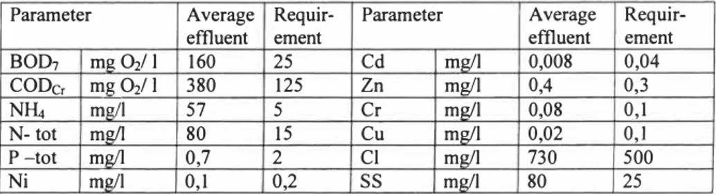
Leachate treatment plant efficiency is presented in the table 2. There is presented average treated leachate concentrations and requirement for wastewater discharge (or leachate) to open water bodies. Treated effluent did not meet to the local requirements as shown in table 2.
Table 2. Leachate treatment results
Parameter Average Requir- Parameter Average
Requir-effluent ement effluent ement
BOD1 ml! Oil I 160 25 Cd mg/I 0,008 0,04
CODc, ID!! Oil I 380 125 Zn mg/I 0,3
NH.i m!!/1 5 Cr mg/I 0,08 0,1
Cu mg/I 0,02 0,1
N-tot mg/I 80
P-tot 0,7 2 Cl mg/I 730 500
Ni m!!/1 0,1 0,2
ss
mg/I 80 25Main problems associated with aerobic treatment method and reasons for treatment failure are:
• A wrong design assumptions and especially a fault made during construction period;
• Leachate has low amount of biodegradable materials and high level of heavily decomposing organic materials and event inhibitors for biological process, It is necessary to add artificial nutrients to the process; such substrates as blood and spirit has been tested. In order to increase treatment efficiency chemicals ( coagulants and flocculants) has been used;
• Due to long retention time (25-30 days) the leachate becomes too cold for a biological treatment process in a low weather temperature periods;
• Highly operation cost due to aeration system and additives of nutrients and chemicals;
• High level of suspended solids in treated leachate cause the sand and peat filters to plug quickly. But backwashing of filter media is not foreseen in the project, therefore replacement of filter media could be applied only.
• Aeration tank and activated sludge process is perfectly suitable for domestic wastewater treatment but for the landfill's leachate treatment another treatment methods shall be apply.
As treatment efficiency has been not reached a need for alternative treatment methods arrived, One of them reverse osmosis, pilot test show good results, but still need for more environment friendly and less costly methods existing.
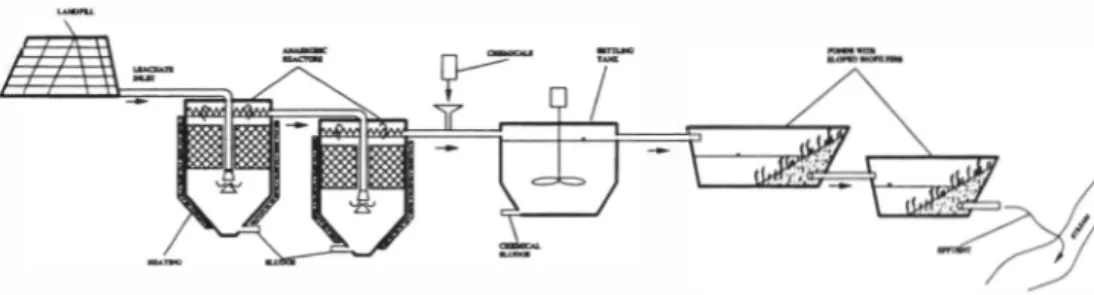
4 ALTERNATIVE TECHNOLOGY FOR LEACHATE TREATMENT Proposed technology for leachate treatment consisting of three stages:
KALMAR, SWEDEN, November 25-27, 2003 • Anaerobic reactors;
• Settling tank;
• Ponds with sloped biofilters.
All stages of treatment have been tested separately, at different places and with different kind of wastewater and leachate.
The main reasons and advantages for introduction of the anaerobic step at the beginning of the treatment technology are follows:
• Brake down strong chain between organic compounds (main purpose of anaerobic process is not a clean leachate but make easier treatment for further steps of process, when strong chains between organic compounds are broken), different forms of nutrients are formed, which are consumed by next stages of treatment;
• During anaerobic process some inorganic ions are eliminated also, such as nitrite, phosphate, chlorate, etc.; metal salts are precipitated in sludge;
• Continue the same process which already takes place inside the landfill (because of inside landfill body there is very limited amount of oxygen, and leachate destruction and degradation process will continue in anaerobic reactors, but in more engineered way);
• Long retention time (according to our experience about 14-20 days);
• Use media to increase volume of biomass (media will provide all advantages of a fixed film processes);
• Stabilized sludge (sludge will be fully stabilized at the bottom of reactor. Sludge production yield is low and sludge will be removed 2-3 time per year only);
• Stable process (high concentration and big volume of sludge is resistant to shock load and variations);
• Low operation cost (no aeration, no mixing or any rotating parts); • No sophisticated operation (no continuously maintenance is necessary).
A shape of the anaerobic reactors allows identify three different zones of the treatment processes in one plant: (a) contact process zone; (b) zone of biofiltration and sludge's return; ( c) zone of separation of the phase. The leachate is supplied into the bottom of the tank and smoothly distributed by special distributing plate. After the leachate flows up through plastic media, it is smoothly collected by special weirs. General layout of the anaerobic reactors is presented in figure 4. Leachate to anaerobic reactors shall be supplied by pump but not continuously, with certain period of time. Applying this approach we could obtain better mixing of sludge and leachate and sludge will not settle down and more active participate into treatment process. In order to facilitate treatment process heating is highly recommended. According to results in pilot test treatment efficiency of anaerobic reactors is about 60% of BOD and 40% of COD. But as has been mentioned earlier, the main purpose of anaerobic stage is not a treatment efficiency it self, but make changes in quality of leachate and hydrolysis of slowly biodegradable materials.
Bioremediation and Leachate Treatment KALMAR, SWEDEN, November 25-27, 2003
Figure 4. General layout of proposed technology for leachate treatment
Second step of treatment is settling tank to settle down sludge, suspended solids and other particles. According to our experience, the best results are grained using chemicals. If chemicals will be applied to leachate without anaerobic stage, results are much worse than after anaerobic pretreatment. Chemicals shall be selected for each case individually. Leachate concentration after settlement could be decreased about 60-80%. However, use of chemicals shall be avoided where it is possible, due to increase of cost and maintenance, and chemical sludge.
Last step of treatment is pond with sloped biofilters. The various pollutant removal mechanisms are applied in sloped biofilter:
• Physical treatment (sedimentation and filtration);
• Chemical (adsorption, oxidation, photolysis, volatilization); • Biological (microbiological decomposition, plant uptake).
The sloped biofilter has shape which ensure increase of filtering area according to rising water level. The working area is consisting from two different steeps of blank slopes. Both slopes can be planted with water plant. Because in the filtering part of the pond's bank the amount of moisture is changing, the sloped biofilter is planted with different types of plants. The most moistured part is planted with ruches (scirpus lacustris), the second part - with reed-maces (typha latifolia) and the third part with the least amount of moisture must be planted with irises (iris pseudoacorus). Plants adsorb the organic product degradation matters and consume their as fertilizers; via empty-boded stems and root systems of the plant the oxygen is introduced into the deeper layers of biofilter; the variability of different types of microorganisms stimulate aerobic and anaerobic processe. Sloped biofilters could be constructed not only in retention ponds, but also in various protection ditches, gutters or canals surrounding the landfill.
The main feature for design of sloped biofilters:
• Hydraulic load 0,1 m3/m2/d;
• Side slope 4: I (minimum); • Size particle of filter 0,5 - 5,0 mm;
KALMAR, SWEDEN, November 25-27, 2003
• Minimum water level 0,6 m;
• Maximum water level 1 ,5 m (depend on plants); • Plant - Scirpus, Typha, Iris and Phragmites.
Treatment efficiency after sloped biofilter is good enough to discharge plant effluent to surface waters. However, pond with biofilters alone is not a solution for leachate treatment, they could be only the last step of treatment.
5 CONCLUSIONS
Main lessons learned during the studies and tests are following:
Under the particular condition at Lapes Landfill in Kaunas the aerobic treatment did not reached design level of required effluent standards, due to shortage of biodegradable organic matters and nutrients, low temperature of substrate.
For the leachate's treatment the natural pollutants removal methods without energy consumption could be applied. Proposed technology consist of two sequenced connected anaerobic reactors, settling tank and two sequenced connected ponds with sloped biofilters. Effluent quality after such treatment process is good enough to discharge to surface waters.
The operation of the plant is very simple, in general all activities are related with disposal of sludge: once or twice per year remove the excess sludge from anaerobic plants, once in few years remove sludge from the bottom of the ponds, and remove sludge from settling tank - probably once or twice per week.
Proposed technology has been verified in pilot plant testing under natural condition for determination of technological parameters.
6 REFERENCES
[ I ] A. Didziapetris. Panevezis Landfill Leachate quality and preliminary design for
leachate treatment plant. Report. 1992.
[2] A. Didziapetris. Anaerobic destruction method for treatment of the Lapes Landfill
leachate. Report. 1995.
[3] P. Didziapetriene, A. Didziapetris. Development of technology for the successive biological wastewater treatment in rural areas. Proceedings of International conference "Small wastewater treatment plants" held in June 6-7, 2002. 42-46 p.
[4] Annual reports of JSC "Kauno svara". Manager ofLapes Landfill. 1999-2002.
[5] Vilnius Technical University and JSC "Hidroprojektas". Technical proposal for Construction of Leachate Treatment Plant. 1996.