Research
ISSN 1104-1374 ISRN SKI-R-06/31-SE
www.ski.se
S TAT E N S K Ä R N K R A F T I N S P E K T I O N
Swedish Nuclear Power Inspectorate POST/POSTAL ADDRESS SE-106 58 Stockholm BESÖK/OFFICE Klarabergsviadukten 90 TELEFON/TELEPHONE +46 (0)8 698 84 00 TELEFAX +46 (0)8 661 90 86
E-POST/E-MAIL ski@ski.se WEBBPLATS/WEB SITE www.ski.se
An Applied Study on the
Decontamination and Decommissioning
of Hot Cell Facilities in the United States
and Comparison with the Studsvik
Facility for Solid and Liquid Waste
Dr. Geoff Varley
Director Commercial Consulting
Chris Rusch
Senior Consultant
July 2006
Background
Under the Act on the Financing of the Management of Certain Radioactive Waste etc.
(1988:1597), sometimes referred to as the “Studsvik Act”, the Swedish nuclear power utilities
make contributions to the Swedish Nuclear Waste Fund at a present rate of 0,2 öre per kWh
generated by nuclear power (approximately 0,02 Euro cents per kWh). The Swedish
parliament decided that the fund ultimately shall cover all expenses for the decontamination
and decommissioning of Swedish non-commercial nuclear installations and research reactors,
including disposition of the associated historic wastes. It is extremely important to ensure that
the rate of contributions to the Swedish Nuclear Waste Fund reflect the future authentic costs
of performing the planned and defined decommissioning and waste disposal tasks over the
relevant future time period. To achieve this, it is essential that the cost estimates associated
with the relevant decommissioning projects are assessed in terms of the correctness of the
basic plans and assumed methodologies, as well as the prudence of the calculated costs.
Purpose of the project
The primary aim of this applied study has been to analyse the cost estimate for
decontamination and decommission of the Facility for Solid and Liquid Waste.
A secondary aim has been to derive results that add to current knowledge on decontamination
and decommissioning methodologies and costs, so as to enhance the basis for preparing high
quality forecasts of future costs related to other facilities. This in turn will enhance the level
of confidence in the assessed fees collected from the nuclear utilities, which of course are
determined in direct relationship to the overall forecast/estimated costs for the planned future
decontamination and decommissioning activities. The comparative study undertaken in this
project contributes to the establishment of progressively greater understanding of the level of
accuracy and the soundness of the principles used for calculations/estimations of future costs.
Results
The study demonstrates very clearly that the approach of comparing Swedish cost estimates
with feedback from actual decommissioning projects completed for similar facilities in other
countries, enhances and extends the knowledge basis as to how future cost estimates can be
improved. The present report is to be seen as part of an active learning process within a
context of collective learning.
The presented applied study reinforces earlier findings in terms of how best to develop
reliable and defensible estimates of cost for decontamination and decommission. In this
regard, the design of the SVAFO study and cost estimate report does not make sufficient
information visible, it has a tendency to rely too much on mechanical reproduction of data
used in other estimates (rather than looking afresh at this specific project) and leaves some
important questions unanswered. Careful attention to the characterisation of an individual
facility is highlighted once again as a fundamental and crucial first step in developing a good
Continued work
This study demonstrates a clear need for ongoing work to develop a comprehensive platform
of decontamination and decommissioning cost information.
Effects on SKI work
SKI can use the present report to draw inferences for analysis of the ongoing evaluation of the
yearly cost estimates that are presented by the company AB SVAFO. The study will therefore
support the present review process regarding estimated dismantling costs of the Facility for
Solid and Liquid Waste.
Project information
At SKI Staffan Lindskog has been responsible for supervising and co-ordinating the project.
Geoff Varley at NAC International has been responsible for the information gathering and
analyses as well as the final preparation of the report.
Research
An Applied Study on the
Decontamination and Decommissioning
of Hot Cell Facilities in the United States
and Comparison with the Studsvik
Facility for Solid and Liquid Waste
By
Dr. Geoff Varley
Director Commercial Consulting
Chris Rusch
Senior Consultant
July 2006
This report concerns a study which has been conducted for the Swedish Nuclear Power Inspectorate (SKI). The conclusions and viewpoints presented in the report are those of the author/authors and do not necessarily coincide with those of the SKI.
May 2006
NAC
I
NTERNATIONALAtlanta Corporate Headquarters
3930 East Jones Bridge Road Norcross, Georgia 30092 770-447-1144 Fax 770-447-1797 32 Bell St Henley on Thames Henley-on-Thames RG9 2BH Oxfordshire United Kingdom 44 1491 636 284 Fax 44 1491 413 023 2-7-10, Sakura-Machi Mail No. 184 Koganei, Tokyo, Japan 81-423-87-6758 Fax 81-423-87-6740
22/25 Bolshoi Strochenovsky Pereulok Office 509
113054 Moscow Russia 7-095-230-6832 Fax 7-503-230-6844 Stoller Nuclear Fuel
A Division of NAC International
1 Baltic Place, Suite 201-A Croton-on-Hudson, New York 10520 914-741-1200
Fax 678-328-1591
©2006 NAC International C-2006-14
The information contained in this report has been prepared by NAC International (NAC) based upon data obtained from sources we consider reliable and/or calculations consistent with technical principles we consider applicable. Neither NAC nor any individual author makes any warranty or representation, expressed or implied, with respect to the accuracy, completeness or usefulness of the information contained in this report, or assumes any responsibility for liability or damage that may result from the use of any information disclosed in this report.
ABOUT THE AUTHORS
G
EOFF
V
ARLEY
Dr. Varley has 30 years of experience in the nuclear industry, more than 17 years as a consultant and manager with NAC and, before that, more than 12 years with U.K. nuclear fuel services company British Nuclear Fuels plc (BNFL). Since joining NAC in April 1988, Dr. Varley has applied his experience and expertise to a wide range of consulting activities, serving clients worldwide. In June 1993 he became general manager of NAC’s Zurich operations. In this capacity, he was responsible for all consulting, database and sales activities performed at NAC's European hub. In July 1996 he opened NAC’s London office and in mid-2004 he was appointed as Director of Commercial Consulting for NAC, a function that he fulfils from a base close to London.
Dr. Varley’s consulting expertise is applied to all nuclear fuel cycle sectors, with a special focus in the enrichment, fuel fabrication and back end (reprocessing, plutonium and uranium recycle, waste management, spent fuel transport and decommissioning) market sectors. Since April 1988, Dr. Varley has visited numerous reactor and fuel cycle service facilities throughout the world.
C
HRIS
R
USCH
Mr. Rusch has more than 30 years of experience in the nuclear industry. In his position as a Senior Consultant, he utilises his great versatility to participate in a wide range of consulting activities, spanning all fuel cycle segments from the front end through waste management and decommissioning.
Before joining NAC, Mr. Rusch was the manager of nuclear fuel at Portland General Electric and was responsible for all phases of nuclear fuel procurement, including strategic and tactical planning, bid preparation, supplier and proposal evaluations, contract negotiation, contract administration, and economic analysis. Significant experience includes management of major projects, technical professionals (in-core fuel management and safety analysis personnel) and annual operating and capital budgets of $1 million and $25 million, respectively.
Mr. Rusch managed the procurement of nuclear fuel for a nuclear plant that consistently ranked among the top 10 plants in the United States with the lowest fuel costs. He organised and directed the evaluation and negotiation teams for the procurement of nuclear fuel fabrication services and directed a multi-department, four-year project to establish a new supplier of nuclear fuel fabrication services.
Mr. Rusch has broad utility experience as his assignments required interfacing with accounting, rates and revenues, finance, legal, power analysis and power operations departments and nuclear plant staff, including reactor engineering, licensing, quality assurance and nuclear engineering groups.
Contents
Executive Summary
1. Introduction ... 1-5
2. General Atomics Hot Cell Facility Description and
Decommissioning Scope... 2-1
2.1 General Atomics Hot Cell Facility Description ... 2-1 2.1.1 Site ... 2-1 2.1.2 HCF Description ... 2-3 2.1.3 Physical Condition Prior to Decommissioning and Current Status ... 2-4 2.1.4 Wastes Stored... 2-7 2.2 Outline of Decommissioning Plan Scope... 2-8 2.2.1 Objectives ... 2-8 2.2.2 Original Planned Scope... 2-9 2.2.3 Actual Scope ... 2-9 2.2.4 Principle Assumptions ... 2-9 2.3 Outline of Planning and Institutional Requirements ... 2-10 2.3.1 General Planning... 2-10 2.3.2 Institutional Requirements... 2-10
3. Overall Work Program at HCF ... 3-1
3.1 Program Outline ... 3-1 3.2 Decontamination and Dismantling Implementation... 3-4 3.2.1 Phase I ... 3-4 3.2.1.1 Characterization ... 3-4 3.2.1.2 Plans, Reports and Approvals ... 3-5 3.2.1.3 IFM Transfer to Temporary Storage ... 3-5 3.2.2 Phase II ... 3-6 3.2.3 Phase III ... 3-9 3.3 Management of Decommissioning Wastes... 3-9 3.4 Milestones and Dates of the Decommissioning Program ... 3-11 3.5 Key Cost Drivers and Sensitivities ... 3-12 3.5.1 Subsurface Characterization Under the HCF Building... 3-12 3.5.2 Quantity of Hot Particles... 3-12 3.5.3 Quantity of Low Level Waste from Decommissioning Debris ... 3-13 3.5.4 Characterization versus Total Phase I Costs ... 3-13 3.5.5 Dismantlement versus Total Cost of Phases II and III... 3-14
4. HCF Decommissioning Cost Analysis... 4-1
4.1 Program Cost Breakdowns... 4-1 4.1.1 General ... 4-1
4.1.2 Man-hour Distribution for Phase I - III... 4-3 4.1.3 Waste Handling and Disposal ... 4-3 4.2 Derived Benchmarking Results ... 4-4 4.2.1 Characterization ... 4-4 4.2.2 Dismantlement ... 4-7 4.2.3 Waste Volume... 4-7
5. Description of Decommissioning Plans for Hot Cells at the
Argonne National Laboratory and the Hanford Reservation .... 5-1
5.1 Decontamination of the Building 200 M-Wing Hot Cells at Argonne National Laboratory ... 5-1 5.1.1 Building 200 M-Wing Hot Cells Description ... 5-2 5.1.2 Decontamination Project Scope ... 5-4 5.1.3 Decontamination Project Implementation... 5-4 5.1.4 Waste Volumes ... 5-5 5.1.5 Project Schedule and Cost... 5-5 5.1.6 Key Sensitivities ... 5-6 5.1.7 Derived Benchmarking Results ... 5-6 5.2 Characterization for the Building 301 Hot Cells at Argonne National Laboratory... 5-7 5.2.1 Building 301 Facility Description... 5-7 5.2.2 Characterization Project Scope ... 5-9 5.3 Building 324 Radiochemical Engineering Cells and Vaults at the Hanford Site ... 5-10 5.3.1 Building 324 Facility Description... 5-10 5.3.2 Decommissioning Project Scope... 5-17
6. Comparison of the GA Hot Cell Facility with the Studsvik HM
Facility ... 6-1
6.1 HM General Information ... 6-1 6.2 HM Physical Details... 6-1 6.3 Decommissioning Scope and Methodology... 6-7 6.3.1 Overview ... 6-7 6.3.2 HM Waste Volumes... 6-8
7. Cost Comparisons... 7-1
7.1 Overall Estimate ... 7-1 7.2 IFM, Waste Removal and Maintenance Costs... 7-1 7.3 Planning and Institutional Costs ... 7-1 7.4 Actual Decontamination and Dismantling ... 7-3 7.5 Other Costs ... 7-4 7.5.1 Project Management ... 7-4 7.5.2 Characterisation ... 7-5 7.5.3 Final Survey ... 7-5 7.5.4 Other ... 7-5 7.6 Cost Information from Argonne Building 200 Decommissioning ... 7-6
7.7 Overall Reasonableness of the HM Cost Estimate... 7-6 7.7.1 Planning and Institutional Support... 7-6 7.7.2 Decontamination, Dismantling and Waste Disposal ... 7-6
Tables
Table 2-1 Description of the HCF Hot Cells ... 2-4 Table 2-2 Radiation Levels Associated with Contamination of the HCF (u Sv per hour)... 2-6 Table 3-1 Waste Form and Disposition (cubic metres) ... 3-10 Table 4-1 HCF Decommissioning Cost Breakdown (1,000s, US$1998) ... 4-1 Table 4-2 HCF Distribution of Man-Hours Expended and Related Costs (1,000s, US$1998)... 4-3 Table 4-3 Waste Volumes (m3) and Costs of Packaging, Transportation and Disposal for All Waste
Forms Excluding Non-Active Waste (1,000s, US$1998)... 4-4 Table 5-1 Building 200 M-Wing Project Cost Breakdown (1,000s US$1994)... 5-5 Table 6-1 Global Comparison of HM and HCF ... 6-7 Table 6-2 Projected Dismantling Wastes from HM Decommissioning (nominal excluding
contingency) ... 6-8
Figures
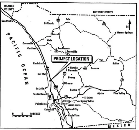
Figure 2-1 Location of the GA site ... 2-1 Figure 2-2 Aerial Photo of the GA site ... 2-2 Figure 2-3 Aerial Photo of the HCF... 2-2 Figure 2-4 Floor Plan of HCF ... 2-3 Figure 2-5 HCF Operating Gallery ... 2-5 Figure 3-1 Removal of Radioactive Waste from the HCF under Phase I ... 3-3 Figure 3-2 Removal of HCF Building Equipment under Phase II ... 3-4 Figure 3-3 Decontamination Work at HCF ... 3-7 Figure 3-4 Further Decontamination Work at HCF... 3-7 Figure 3-5 Hot Cell Dismantling ... 3-8 Figure 3-6 Hot Cell After Dismantling of the Surrounding Facility ... 3-9 Figure 3-7 HCF Manipulators Shipped to GE Facilities... 3-11 Figure 5-1 Site Map of Argonne National Laboratory ... 5-2 Figure 5-2 Plan View of Building 200 Service Floor Showing Location of
the Megacurie Hot Cells ... 5-3 Figure 5-3 Plan View of Building 200 Main Floor Showing Location of the Kilocurie Hot Cells .... 5-3 Figure 5-4 Main Floor: Beta/Gamma Survey Units Locator Map... 5-8 Figure 5-5 Service Floor: Beta/Gamma Survey Units Locator Map... 5-9 Figure 5-6 Hanford Site... 5-11 Figure 5-7 Area and Location of 324 Building ... 5-12 Figure 5-8 Cut-away of the 324 Building Showing the High-Level Vault, Low-Level Vault, and the
Radiochemical Engineering Cells ... 5-13 Figure 5-9 324 Building Basement Plan... 5-14 Figure 5-10324 Building First Floor Plan ... 5-15
Figure 5-11324 Building Second Floor Plan ... 5-16 Figure 5-12324 Building Third Floor Plan ... 5-17 Figure 6-1 Cut-Away View of HM ... 6-2 Figure 6-2 Cut-Away Schematic of HM Tank Rooms... 6-2 Figure 6-3Cut-Away Schematic of HM Hot Cell, Operating Room and Hot Cell Waste
Accesses ... 6-2 Figure 6-4 Cut-Away Schematic of HM Hot Cell Drum Transfer Arrangements and Cementing
Station ... 6-2 Figure 6-5 Photograph of Hot Cell Operating Room ... 6-3 Figure 6-6 Photograph of Drum Transfer Port Above HM Hot Cell ... 6-4 Figure 6-7 Photograph of Additional Accesses Above HM Hot Cell ... 6-4 Figure 6-8 Photograph of HM Ventilation Room ... 6-5 Figure 6-9 Photograph of HM HEPA Filters in Ventilation Room ... 6-6
Glossary
ANL Argonne National Laboratory located near Chicago, Illinois, USA DOE U.S. Department of Energy
DOE-EM U.S. Department of Energy - Environmental Management DOHS State of California - Department of Health Services
DSSI Diversified Scientific Services, Inc., Kingston, Tennessee Envirocare Envirocare of Utah, Inc., Salt Lake City, Utah GA General Atomics
GA Site General Atomics Torrey Pins Mesa Facility, San Diego, California HCF Hot Cell Facility at the GA Site
HEPA High Efficiency Particulate Air HLW High Level Radioactive Waste
HTGR High Temperature Gas-cooled Reactor IFM Irradiated Fuel Material
INEL Idaho National Engineering Laboratory LLW Low Level Radioactive Waste
NAC NAC International
NRC U.S. Nuclear Regulatory Commission NTS Nevada Test Site LLW Facility, Nevada
NWPF Nuclear Waste Processing Facility at General Atomics ORISE Oak Ridge Institute for Science and Education
Perma-Fix Perma-Fix Environmental Services, Inc., Gainesville, Florida PIE Post Irradiation Examination
RERTR Reduced Enrichment Research and Test Reactor SSI Swedish Radiation Protection Authority
Executive Summary
Overview
This report presents the plans, processes and results of the decontamination and
decommissioning of the Hot Cell Facility in Building 23 at the General Atomics Torrey Pines Mesa Facility (HCF) and compares the program and cost of decommissioning HCF with the Swedish cost estimate for decontamination and decommissioning of the HM hot cell and wastes treatment facility at Studsvik in Sweden.
Construction of the HCF was completed in 1959 with laboratories and remote operations facilities covering a total area of 690 square metres. The HCF had three main hot cells and was licensed to:
Receive, handle and ship radioactive materials;
Remotely handle, examine and store irradiated fuel materials; Extract tritium (engineering scale);
Support new reactor production development;
Develop, fabricate and inspect UO2 - BeO fuel materials.
The HM facility in Studsvik was constructed to handle and package medium-active solid and liquid wastes, prior to disposal. Central to the facility is a conventional hot cell including three work stations, serviced by master slave manipulators. Other parts of the facility include holding tanks for liquid wastes and slurries, a centrifuge room, as well as an encapsulation station where drummed wastes can be encapsulated in cement, offices, laboratories and workshops and so on, as well as building and cell ventilation systems.
HCF Decontamination and Decommissioning
Decontamination and decommissioning of the HCF took place during 1993 through 2001. The objective was to obtain regulatory release of the site so that it could be used on an unrestricted basis. Based on data from extensive hazardous and radiological materials characterization, GA evaluated four decommissioning options and selected dismantling as the only option that would satisfy the decommissioning objective.
The decontamination and decommissioning scope included the following actions. 1. Remove the legacy waste that consisted of radioactive wastes stored at the HCF
consisting of 21.434 kgHM of irradiated fuel material (IFM) that was owned by the U.S. Department of Energy and store the waste in temporary storage set up at the GA site. This activity was accomplished during Phase I of the project which also included planning, preparation and characterization of the facility.
2. Actual Decontamination and Dismantlement occurred during Phase II. The activities included:
a. Dismantlement of the building structure surrounding the hot cells and then finally dismantlement of the hot cell block
b. Soil remediation
c. Handling and disposal of decommissioning wastes d. Confirmatory surveys
3. Final site release occurred during Phase III.
4. The final activity which occurred substantially after Phases II and III were complete was the shipment of the IFM to a DOE facility.
Cost Comparison
The overall decommissioning costs for HM (estimated) and HCF (actual) are MSEK 43.9 (2001 money values) and $35.5 million (1998 money values) respectively. Normalizing to 2001 SEK, the HCF equivalent value is approximately MSEK 392.
The HCF and HCF structures are approximately the same size on a volumetric basis. The volume of the HM hot cells is about 12 percent greater than at HCF but the HCF had 27 percent more surface area due to the existence of three separate cells. Of potential importance is that the contamination levels on the hot cell surfaces were not equal. The HCF facility was highly contaminated from such activities as band-sawing irradiated high temperature gas cooled reactor fuel, which produced aerosols of fuel and graphite
particles that spread throughout the hot cells. On these grounds it might be expected that the HCF actual costs would be higher than HM estimates. However, a factor of almost nine times higher seems to be exceptional.
The very large difference in fact stems from a number of special circumstances at HCF that need to be backed-out of a cost comparison in order to make it meaningful. One
special requirement was the removal and safe management of irradiated fuel material, including high enriched uranium, the costs for which were considerable. Another cost related to maintenance of the building, including substantial repairs and replacement before decommissioning could commence. The costs of waste disposal also vary
substantially, in terms of unit costs and the proportion of dismantling waste that needs to be sentenced to a radioactive waste repository. Finally, the HCF decommissioning project was funded largely by the U.S. Government. This added significant cost to the planning and preparation of the project including voluminous reports (for example the
characterization report was 680 pages). The cost of project management and compliance also were increased enormously because of government oversight. Government
involvement also resulted in a very conservative approach to managing dismantling wastes.
Concerning the actual labour resources expended on decontamination and dismantling efforts, the HM and HCF projects are quite comparable.
Main Conclusions
The available information for HM has been evaluated and compared, to the extent possible, with the HCF decommissioning costs and other selected NAC derived decommissioning cost benchmarks. In summary the main conclusions for the HM decommissioning cost estimate are as follows:
P
LANNING ANDI
NSTITUTIONALS
UPPORTTheoretical estimates of planning and other support activities can have a tendency to assume optimal circumstances and tend not to account for potential changes of
circumstances in, for example, the regulatory environment and requirements. It therefore may be prudent to review in general the cost allowances for efforts in this category. In any event, based on advice from SKI, SKI and SSE (Swedish Radiation Protection Authority) oversight will apply to the HM decommissioning project, with attendant costs.
D
ECONTAMINATION,
D
ISMANTLING ANDW
ASTED
ISPOSALThe estimate for decontamination and dismantling overall appears to be reasonable. Areas where additional costs could occur (e.g. hot cell concrete) have been identified in this report. Additional cost for waste disposal would be the main consequence if such
contamination were found. One of the big differences between the plan and the outcome at HCF was the amount of dismantling waste that had to be disposed of as active waste. Due to the government funding of the HCF project, the determination between clean concrete and radioactive concrete was made very conservatively. The HM facility appears to be in much better radiological condition overall than HCF but it cannot be discounted that surprises are found and/or regulatory requirements change regarding the dumping of waste. If an engineered solution (concrete cutting) were required to dismantle the hot cell, a substantial additional cost could apply.
C
HARACTERISATIONFollowing on from the above comments, the HM estimate does not include any significant allowance for characterisation/radiological mapping of the facility prior to designing and planning the decontamination and dismantling work. The development of an accurate picture before proceeding with the work normally is a prudent and beneficial step to take. An additional estimated cost of up to MSEK3 could apply for such an exercise.
U
NCERTAINTIES/C
ONTINGENCIESThe treatment of uncertainty in developing the HM cost estimate seems to have followed the pattern of other cost estimates analysed by NAC, whereby a round percentage number has been added to certain base estimates. As recommended in reference 4, a more focused approach based on identifying the main potential cost sensitivities and then dealing with them in a more individual manner would be preferable.
1. Introduction
Statenskärnkraftinspektion (SKI) charged NAC International with the task of conducting an applied research study into methods and costs relevant to the decontamination and decommissioning of the Studsvik Facility for Solid and Liquid Waste (HM). To fulfil this task, NAC has focussed on analysis of the plans, processes and results of the
decontamination and decommissioning of the Hot Cell Facility at the General Atomics Torrey Pines Mesa Facility, located about 21 kilometers north of San Diego, CA (hereafter referred to as the HCF). The study includes a comparison of this information with the decommissioning plan and cost estimate for the Studsvik Facility for Solid and Liquid Waste (HM) in Sweden (hereafter referred to as the HM). The HM cost estimate is contained in report SEP 01-320, rev 0 prepared by Westinghouse Atom AB for AB SVAFO under order number A.106306.
Additional insights and benchmarks, to the extent possible, are presented based on the analysis of decommissioning project information available for the following facilities: the hot cells at Building 324, Hanford Reservation in Washington State;
the hot cells that were located in Building 200 at the Argonne National Laboratory (ANL) located about 40 km from Chicago, Illinois, USA;
Storage tanks located in Building 310 also at ANL
Relevant benchmarking information is available for the Building 200 project. More general information is included on the other two projects for completeness, as one or more of these are expected to be decommissioned in the relatively near future and could provide information of interest to SKI at a later time.
This report presents the conclusions of NAC’s analyses and comparisons. It includes a full analysis of the HCF, the derivation of relevant benchmarking results from that decommissioning program and a prudence review of the HM cost estimate, looking at the reasonableness of the cost estimate as well as the completeness of the estimate and related logistics.
2.
General Atomics Hot Cell Facility
Description and Decommissioning
Scope
2.1
General Atomics Hot Cell Facility Description
2.1.1 Site
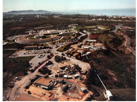
The HCF was located at the GA Site which is about 21 kilometres north of the center of San Diego, CA, USA. The HCF was situated at the north central sector of this facility, about 100 metres above sea level and 1.6 kilometres from the Pacific Ocean. Figure 2.1 through Figure 2.4 indicate the location of the GA Site and Building 23 (HCF) and the HCF floor plan. The climate at the site is characterized as Semi-Arid Mediterranean with an average annual rainfall of 26.4 cm.
Figure 2.2 Aerial Photo of the GA site
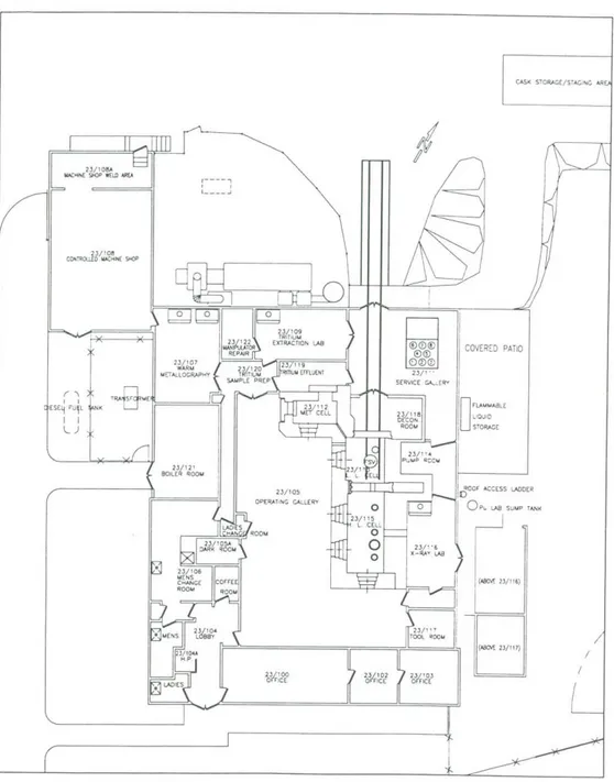
Figure 2.4 Floor Plan of HCF
2.1.2 HCF
Description
The HCF was designed and built by Bechtel Corporation. Construction of the HCF was completed in 1959 with laboratories and remote operations facilities covering a total area of 690 square metres. The HCF is surrounded by a fenced service yard with a total area of 4,340 square metres that included concrete pads for staging heavy equipment and
The HCF had three main hot cells and was licensed to receive, handle and ship radioactive materials; remotely handle, examine and store irradiated fuel materials; extract tritium (engineering scale); support new reactor production development; and develop, fabricate and inspect UO2 - BeO fuel materials.
Table 2-1 provides a description of the HCF hot cells. Table 2-1 Description of the HCF Hot Cells
Name of Cell Length (m) Width (m) Height (m) Wall Thickness (m) Wall Concrete Type No. of Operating Stations High-Level 5.49 2.44 4.57 1.07 – 1.52 Magnetite 3 Low-Level 3.05 2.59 4.57 0.81 – 0.91 High-density 1 Metallography 2.74 1.52 3.51 0.86 – 0.91 High-density 1
2.1.3
Physical Condition Prior to Decommissioning and Current
Status
Prior to the decommissioning project, the HCF was maintained in a shutdown, safe, surveillance and maintenance mode. Specifically,
Utility services (water, electricity and natural gas) were connected and functional. Building air ventilation and HEPA-filter systems, instrument air supply compressors, and
criticality and effluent monitoring systems were operational.
Manually actuated and automated fire alarm/suppression systems were operational. Radiological and security alarm systems were normal.
Remote handling systems and auxiliary support equipment were operational or available for activation and use.
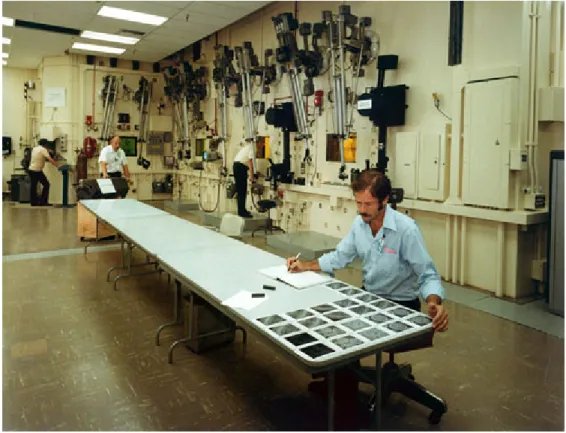
About five years elapsed between the time that research and development activities stopped in 1991 until actual decommissioning work commenced in May 1996. Figure 2.5 (Operating Galley) indicates that the facility was generally in good physical condition at the commencement of decommissioning work.
Figure 2.5 HCF Operating Gallery
In 1994, the HCF and surrounding fenced service yard were characterized for radiological contamination, hazardous materials contamination and asbestos. The characterization included the collection of 206 soil samples, 405 concrete samples, 38 asphalt samples, 28 vegetation samples, 41 asbestos samples, 90 hazardous material constituent samples and 211 miscellaneous samples (floor tiles, plaster, etc). The HCF and surrounding yard were contaminated with radioactive elements and isotopes
including Cobalt-60, Cesium-137, Europium-156, Strontium-90, Uranium and Thorium. The results of the characterization were as follows:
Seventy-nine percent of the building floor area and 50 percent of the wall area were radiologically contaminated. Based on results from concrete samples, Cs137
contamination was in the range of between 0.00274 and 321.2 Bq per gram and Co60 contamination was in the range of between 0.00352 and 11.4 Bq per gram. Many hot particles (fission products in fuel fragments [typically microscopic] from destructive examination of irradiated fuel and containers) were located. General radiation levels associated with these contaminated surfaces are listed in Table 2-2.
Core drilling verified subsurface contamination. However, the deepest cores that were 9.1 metres below grade level discovered no ground water contamination. Based on results from soil samples, Cs137 contamination was in the range of between 0.00296 and 0.179 Bq per gram and Co60 contamination was in the range of between 0.0033 and 0.04 Bq per gram.
Hazardous constituent surveys indicated that 23 percent of the floor and wall area was contaminated with low levels of PCBs, semi-volatile organic compounds and metals. Core sampling indicated subsurface contamination at low levels in areas where oils were used.
21 of 41 samples tested for asbestos a tested positive
A majority of the fenced yard surface had radiological contamination. Subsurface cores collected up to 1.0 metre in depth indicated detectable radioisotope levels.
Floor materials with both hazardous material and radiological contamination were classified as mixed waste and handled accordingly.
Table 2-2 Radiation Levels Associated with Contamination of the HCF (u Sv per hour)
Location Radiation Level -General Area
Radiation Level - Peak Reading
Corridor near Room 120 2.0
Decontamination Room – general area 200.0 1,000.0
High-Level Cell
Very high due to storage of HLW
Low-Level Cell 500.0 to 1,000.0 10,000.0 Machine Shop 2.0 to 4.0
Manipulator Repair Room 150 1,000.0 Metallography Cell 50,000.0
Pump Room <1.0
Service Gallery Room – general area 20.0 1,000.0 Tritium Effluent Room 2.0 to 5.0
Tritium Extraction Room 3.0 to 18.0 Tritium Sample Preparation Room 2.0 to 10.0 Warm Metallography Room (cold side of to
The current status of the facility is as follows: All HCF equipment was removed.
The HCF was completely dismantled.
The yard area was remediated to radiation and contamination levels less than the release standards for future industrial land use.
Irradiated fuel material (IFM) has been shipped to INEL for interim storage.
The Department of Health Services (DOHS) and the Nuclear Regulatory Commission (NRC) released the site for unrestricted use.
2.1.4 Wastes
Stored
In early 1993, at the time that HCF was accepted by DOE-EM for decontamination and decommissioning, the principle radioactive wastes stored at the HCF consisted of 21.434kgHM of IFM that was owned by DOE. The IFM were collected and retained at the HCF as part of a succession of hot cell PIE projects in support of a number of DOE-sponsored fuel development programs. The IFM was separated by fuel types into two packaging groups including HTGR IFM and RERTR IFM.
The HTGR IFM was consolidated in a single fuel mass comprised of three fuel forms - coated fuel particles, fuel compacts and fuel pebbles. The uranium enrichment of the HTGR IFM varied from 10.0 to 93.15 w/o U235. The total weight of the HTGR IFM was 10.668 kg. The forms are described a follows:
Coated Fuel Particles – consisted of solid, spherical sintered ceramic fuel kernels composed of UC2, UCO, UO2, (TH,U)C2, or (Th,U)O2, substrate, isotopically coated with discrete multi-layered fuel particle coatings, composed of pyrolitic carbon (PyC) and silicon carbide (SiC).
Fuel Compacts – coated fuel particles bound in solid, cylindrical, injection-moulded, high-temperature heat-treated compacts, the binding matrix of which consists of carbonized graphite shim, coke and graphite powder.
Fuel Pebbles – coated fuel particles bound in solid, spherical, injection-molded, high-temperature heat-treated pebbles, the binding matrix of which consists of carbonized graphite shim, coke and graphite powder.
The RERTR IFM were comprised of 20 irradiated TRIGA elements consisting of a uranium-zirconium hydride fuel matrix clad in Inconel 800H tubing. The elements were
1.3 cm in diameter and 56cm in length. Thirteen of the elements were intact while seven had been sectioned for PIE. The elements had three distinct uranium enrichments of 20, 30 and 45 w/o U235. The total weight of the RERTR IFM was 10.766 kg.
The enclosures that contained the IFM material and some non-fuel element components were included in the IFM packaging and weighed 45.47 kg.
2.2
Outline of Decommissioning Plan Scope
2.2.1 Objectives
The objective of the HCF decommissioning project was to obtain regulatory release of the site so that it could be used on an unrestricted basis. Prior to establishing the Decommissioning Plan, GA performed extensive hazardous and radiological materials characterization of the HCF and associated site. Based on the characterization data, GA evaluated the four decommissioning options identified in NRC Regulatory Guide 1.86 to determine and select the option(s) that would satisfy the decommissioning objective. The four NRC options are as follows:
Leave in Place – under this option, the HCF would have been maintained in a secure shutdown mode. This option was evaluated as being unacceptable because the
decommissioning objective would not be met due to the extensive contamination in the HCF.
Entombment – under this option, the HCF would have been entombed, thereby entirely securing the hazardous and radioactive contents of the structure. This option was evaluated as being unacceptable because the decommissioning objective would not be met due to the contaminated soil surrounding the HCF not being dealt with.
Decommissioning in Place – under this option, the HCF would have been
decontaminated and decommissioned but the structure would be left in place. This option was evaluated as being unacceptable because access to decontaminated areas would have required extensive building dismantlement such that the building would have been unusable after the project was complete.
Dismantlement – under this option, the HCF equipment and structure would be dismantled, the surrounding soil remediated and the site cleared for unrestricted use through NRC and State of California final inspections. This option was selected because it met the decommissioning objective.
2.2.2
Original Planned Scope
As a result of the evaluations described in section 2.2.1, the dismantlement option was selected. The principle tasks included the following actions.
1. Site Characterization, 2. Assessment of Alternatives
3. Relocation of Legacy Waste (IFM) to another facility at the GA Site 4. Site Preparation for Decommissioning
5. HCF Decommissioning Operations 6. Soil Remediation
7. Handling and Disposal of Decommissioning Wastes 8. Confirmatory surveys
9. Final Site Release
10. Shipment of IFM to a DOE facility
2.2.3 Actual
Scope
The program of work was carried out in three main phases; preparatory work, actual decontamination and dismantling and closeout work. Several events or situations caused significant changes to schedules or waste quantities and to the scope of the HCF
decommissioning project.
Hot particles were found in the soil staging area, which caused a 13-month delay in the completion of Phase 3 of the project. Over 1,400 cubic metres of soil that was originally determined to be “clean” was disposed of as LLW. This was the major factor in the increase of the quantity of contaminated soil discussed below.
LLW from dismantlement debris was four times the projected quantity but, in terms of cost, there was no impact because the final quantities of other waste categories were lower than projected (see Table 3-1).
The volume of contaminated soil was 14 times the projected volume. This caused a significant increase in the scope of soil waste handling and disposal.
2.2.4 Principle
Assumptions
The entire decontamination and decommissioning project was contingent on acceptance of the HCF into the DOE-EM Surplus Facility Management Program. After DOE-EM acceptance was secured, a cost-sharing agreement was established.
A significant portion of the utilization of the HCF had been devoted to DOE-sponsored hot cell examinations of spent nuclear fuel. Based on this utilization, DOE and GA agreed to a cost sharing plan in which DOE would be responsible for 76 percent of the decontamination and decommissioning costs and GA the remainder.
This agreement lead to the disposition plan for the IFM. Owing to the fact that the waste was related to DOE-sponsored projects, it was agreed that the IFM eventually would be transferred to a DOE facility. However, the decontamination and decommissioning of the HCF could not proceed until IFM was removed from the HCF and so the IFM initially was moved to a temporary location.
2.3
Outline of Planning and Institutional
Requirements
2.3.1 General
Planning
With the decline in nuclear fission research and increasing development surrounding the GA Site, GA management made the decision to decontaminate and decommission the HCF and associated fenced service yard. Accordingly, in early 1993, GA submitted a request to DOE that the HCF be designated a candidate site under the Surplus Facility Management Program and the request was accepted in the same timeframe.
On December 14, 1994 GA formally notified the NRC of its intent to “cease” principal activities at the HCF. A Decommissioning Plan was then prepared.
As noted in section 2.2.4, DOE and GA reached a cost-sharing agreement for the decommissioning project. After the cost-sharing agreement was reached the DOE Oakland Project Office awarded contract DE-AC03-84SF11962 to GA for the Phase I scope of work outlined in section 3.1.
Subsequently, in January 1996, another contract, DE-AC03-95SF20798 was awarded for the Phase II and III scope of work also outlined in section 3.1.
2.3.2 Institutional
Requirements
The HCF was regulated under the GA Special Nuclear Materials License SNM-0696 issued by the NRC and the Radioactive Materials License 0145-80 issued by the Radiological Health Branch of the DOHS. Release criteria for soil, building materials,
concrete, and asphalt were based on criteria in these licenses. The final release guideline values were calculated specifically for the site and represented incremental
concentrations above background values. NRC’s Manual for Conducting Radiological Surveys in Support of License Termination (NUREG/CR-5849) provided guidelines for calculating isotopic concentrations in soil that corresponded to maximum permissible gamma exposure rates and dose rates.
There were a number of plans, reports and approvals required for the project. The plans and reports are listed in section 3.1. The documents that required regulatory approvals are listed below along with the government organization granting approval.
1. Environmental Assessment (NRC Finding of No Significant Impact [FONSI]) 2. Draft and Final QA Program Plans (DOE)
3. Draft and Final Health and Safety Plans (DOHS)
4. Operational Readiness Reviews to Conduct Phase I, IFM transfer and Phases II and III (DOE)
5. IFM and HCF Characterization Reports (approved by DOE) 6. Decommissioning Plan (approved by DOHS and NRC) 7. Draft and Final Closure Reports (NRC)
8. Request to Release HCF for Unrestricted Use (approved by DOHS and NRC) 9. Contaminated Soil Shipment Approval (DOHS and NRC)
10. Licensing Applications, Notices, Plans, Reports and Approvals (INEL, DOE and NRC) for shipping IFM to INEL
3.
Overall Work Program at HCF
This section presents a summary of activities carried out in the three phases of the actual work program. Additional details are provided for selected parts of the program, including on characterisation, transfer and storage of irradiated fuel materials and the management of decommissioning wastes. Items that significantly affected the project cost also are discussed.
3.1 Program
Outline
The work scope included the following phases: Phase I (April 1993 – October 1995)
1. Remove the DOE irradiated fuel from the HCF
2. Remove other radioactive waste from the HCF (Figure 3.1)
3. Assure that the HCF meets DOHS and NRC health and safety standards
4. Characterization of the site with respect to contamination from hazardous materials, radioactive isotopes and asbestos.
5. Define the overall scope of the decommissioning project based on characterization data
6. Establish project management documentation, project documentation and project controls required by DOE, DOHS and NRC.
7. Prepare and obtain approvals of the Decommissioning Plan 8. Complete the following documents and reports:
a. Project baseline
b. Inventory reports on legacy waste including IFM
c. IFM Characterization and Site and Facility Characterization Plans and Reports
d. Hazards Analysis e. Asbestos Surveys
f. Project Plan/Project Management Plan for Phase I g. Concrete and Soil Sampling and Testing Plan h. Decommissioning Plan
i. Low Level Waste Certification Plan j. Waste Minimization Plan
k. Safeguards and Security for IFM
l. Environmental Assessment - Decontamination and Decommissioning m. Environmental Assessment – (IFM relocation)
n. Procedures for Decontamination and Decommissioning Phase II (August 1995 – June 2001)
1. Remove building equipment (Figure 3.2)
2. Recycle cell operations equipment to the extent possible 3. Asbestos remediation
4. Remove non-load bearing walls
5. After 1 - 4 were complete, dismantle the HCF building 6. Characterize, package, and ship radioactive waste
7. Treat mixed waste at the NWPF to separate hazardous waste from radioactive waste or, if separation is not possible, ship mixed waste to an appropriate facility
8. Package and ship contaminated soil to one of two facilities depending on contamination levels
9. Complete the following documents and reports:
a. Operational Readiness Review for Phase II and III b. Draft and Final QA Program Plans for Phases II and III c. Project Plan/Project Management Plan for Phases II and III d. DOE Matrix Analysis Report
e. Draft and Final Health and Safety Plan
f. IFM Transfer Operational Readiness Review Report g. IFM Transfer and Storage Procedures
h. Progress Reports involving costs, labor, schedules, trends and waste minimization and shipping
Phase III (January 2000 – September 2001) 1. Confirmatory Survey
2. Final Site Certification activities
3. Complete the following documents and reports: a. Final Radiological Survey Plan and Report b. Draft and Final Closure Reports
c. Final Project Closeout Report
d. Release from SNM and By-product Licenses 4. Shipment of IFM to INEL (August 2002 - September 2003) Figure 3.1 Removal of Radioactive Waste from the HCF under Phase I
Figure 3.2 Removal of HCF Building Equipment under Phase II
3.2
Decontamination and Dismantling
Implementation
3.2.1
Phase I
Phase I consisted of three main activities including characterization of the HCF and surrounding yard; preparation of plans and reports, receipt of regulatory approvals; and removal of IFM and other waste stored at the HCF.
3.2.1.1 Characterization
The purpose of characterization activities was to provide the information necessary to accurately define the extent and magnitude of HCF contamination. The information gathered was used to:
determine decontamination and decommissioning techniques, establish project schedules,
estimate project costs, estimate waste volumes,
The HCF and surrounding fenced service yard were characterized for radiological, hazardous materials, asbestos and soil contamination. The characterization included the collection of 206 soil samples, 405 concrete samples, 38 asphalt samples, 28 vegetation samples, 41 asbestos samples, 90 hazardous material constituent samples and 211 miscellaneous samples (floor tiles, plaster, etc). Section 2.1.3 provides the results of the characterization. In addition, visual and radiological surveys were conducted.
The three hot cells were highly contaminated and had high general area exposure rates (see Table 2-1). Therefore, characterization was limited and was based on knowledge of the processes carried out in the cells and limited measurement. A committee of GA experts spent two months examining the HCF operations log books to document the materials brought into the cells in an effort to aid the characterization of the cells.
3.2.1.2
Plans, Reports and Approvals
After the contracts were awarded to GA, preparation for mobilisation on the project was accomplished through a planning process that required a number of plans, reports and regulatory approvals that are outlined in sections 2.3.2 and 3.1. Reference 1 contains a detailed chronology of the project including the dates of issuing the plans, reports and approvals.
3.2.1.3
IFM Transfer to Temporary Storage
In order to dismantle the HCF (Phase II), the IFM and other waste stored in the hot cells at the HCF had to be transferred to a location away from the HCF and surrounding service yard. Section 2.1.4 describes the IFM that was separated by fuel types into two packaging groups, including HTGR IFM and RERTR IFM. The IFM was then loaded into two separate shipping casks.
The casks were transported from the HCF to temporary storage facilities at the GA site. During December 1995 through August 2003, the casks were moved three times and stored at three separate locations at the GA site. In September 2003, the IFM was loaded into an NAC-LWT shipping cask and shipped to INEL in Idaho, USA.
3.2.2 Phase
II
This phase dealt primarily with building and hot cell dismantlement and packaging and shipping of (1) wastes from dismantlement, and (2) contaminated soil. Section 3.3 discusses waste disposition; therefore, dismantlement is the focus of this section. The dismantlement task was accomplished in five steps as follows:
1. For rooms surrounding the main hot cell structure, the tasks were to: a. remove equipment and materials,
b. decontaminate walls, floor and ceiling using a number of possible techniques1 (essentially state-of-the-art) evaluated in the
Decommissioning Plan (Figure 3.3 and Figure 3.4 show blasting and application of strippable paint), and
c. remove non-load bearing walls. 2. For hot cells, the main tasks were to:
a. remove equipment and materials, b. remove steel liner, and
c. decontaminate concrete walls, floor and ceiling using remotely operated cleaning methods followed by abrasive cleaning
3. Following decontamination of the HCF, a health physics survey was performed to verify preparations for shutting down the HEPA system.
4. Following shutdown of the HEPA system, dismantlement2 continued with removal of the:
a. HCF roof
b. walls of the rooms surrounding the hot cells and associated slab c. ceiling, walls and floors of the hot cells (Figure 3.5)
d. hot cell foundation, pits and wells
5. Soil remediation consisting of removing “clean” soil to the SSA and packaging and shipping contaminated soil.
At one point in the dismantling sequence, only the hot cell structure was left intact, see Figure 3.6 (last photo on Page Photo 4 of PBS VL-GA-0012).
1. Examples of these are: Vacuum cleaning, damp cloth wiping, strippable coatings, hydro blasting, steam cleaning, abrasive blasting, scabbling, spalling, complexing agents/solvents/acids/caustics or CO2
blasting.
2. This involved concrete cutting. Holes were drilled in the concrete about 2.5 cm apart and the remaining concrete was cut using concrete saws, so the technique was standard.
Figure 3.3 Decontamination Work at HCF
Figure 3.6 Hot Cell After Dismantling of the Surrounding Facility
3.2.3 Phase
III
Following removal of all contamination, a final radiation survey was conducted by GA. In addition, independent surveys of the yard were conducted by the Environmental Survey and Site Assessment Program of the Oak Ridge Institute for Science and
Education (ORISE) and the NRC and, to a more limited degree, DOHS. Based on the GA survey and the independent surveys, in 2000, the NRC and DOHS released the HCF site for unrestricted use.
3.3
Management of Decommissioning Wastes
There were five main waste types generated from the project including asphalt, concrete rubble, construction material debris, facility equipment and soil. Table 3-1 lists these waste types, associated quantities and the name of the organization that received shipments of the waste.
All waste shipped for burial was in solid form. With the exception of a small amount of mixed waste sent to Diversified Scientific Services Incorporated (DSSI) for incineration, the liquid waste generated during the project was solidified or treated at the Nuclear Waste Processing Facility (NWPF) to yield a solid waste form.
With the exception of the bulk soil shipments to Envirocare, all waste was packaged3 in metal boxes (1.2m x 1.2m x 2.1 m) or 208-liter metal drums and shipped by truck. The bulk soil waste was wrapped in heavy plastic, transported by truck to rail facilities in Los Angeles, loaded on flatbed rail cars and transported by rail to Envirocare.
Table 3-1 Waste Form and Disposition (cubic metres)
Source Waste Type
Baseline Plan Projected
Volume Volume Actual Projected Actual /
Organization Receiving Waste
Concrete and building debris
and equipment LLW 648.46 2,674.20 4.1 U.S. Ecology (Hanford)
Debris including contaminated Pb Mixed LLW 26.05 13.76 0.5 DSSI, Envirocare, SEG-Duratek, Alaron & Perma-fix Building debris Clean 625.81 311.49 0.5 Miramar Landfilla
Soil
Radioactiveb
particles in
soil 235.03 1,682.711,632.73 14.1 Envirocare NTS Soil Mixed 65.13 0.00 0.0 None
Asphalt Clean 379.45 28.32 0.1 Miramar Landfill
Asphalt Radioactive particles 65.13 31.15 0.5 Envirocare
a. This is landfill owned and operated by the City of San Diego.
b. The total projected contaminated soil was 235.03 cubic metres. The actual quantity of contaminated soil was (1,682.71 + 1,632.73) = 3,315.44 cubic metres.
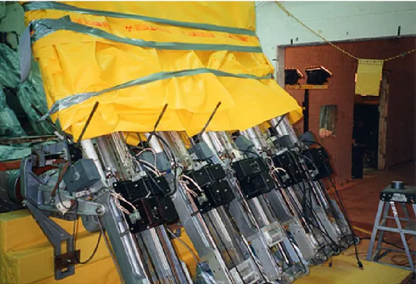
Manipulators (Figure 3.7) and lead glass windows from the HCF were recycled by shipping this equipment to GE facilities.
Figure 3.7 HCF Manipulators Shipped to GE Facilities
3.4
Milestones and Dates of the Decommissioning
Program
Significant milestones and dates regarding the HCF decommissioning are listed below: Early 1993 – GA proposed and DOE-EM accepted the HCF as a candidate facility for
the Surplus Facility Management Program.
May 1994 - Site and Facility Characterization Plan completed and issued.
November 1994 – Facility sampling and soil coring for characterization evaluation were completed.
January 1995 – Radiological waste shipments begin.
December 1995 – Irradiated fuel materials transferred to Building 30 at the GA Site. May 1996 – Interim NRC approval of the GA Hot Cell Facility Decommissioning Plan
and decommissioning activities commenced.
January 1997 – Final NRC approval of the GA Hot Cell Facility Decommissioning Plan. March 1997 – Shipment of equipment including manipulators, periscope, metallograph
to GE for reuse.
October 1998 – Dismantlement of HCF completed.
September 1999 – Soil and debris shipments to Envirocare (LLW waste facility in Utah) completed (174 shipments).
March 2000 – GA confirmatory radiological surveys and independent verification surveys of the HCF site completed.
August 2000 – HCF site released to unrestricted use.
May 2001 – contaminated soil and asphalt shipments to the NTS completed (100 shipments).
June 2001 – all radiological waste disposal activities completed. September 2001 – HCF decommissioning activities completed.
3.5
Key Cost Drivers and Sensitivities
3.5.1
Subsurface Characterization Under the HCF Building
Although some coring was conducted under the building during characterization, the number of samples was not sufficient to characterize the extent of soil contamination. The depth of building vaults and pits precluded detailed investigation of the soil beneath the vaults and pits. The quantity of contaminated soil could only be determined after the building was dismantled and debris removed. As noted in Table 3-1, the volume of contaminated soil was approximately 10 times greater than expected, partially due to this characterization difficulty. An estimated 1,250 cubic metres of the difference can be attributed to this problem.
3.5.2
Quantity of Hot Particles
Over 1,410 cubic metres of soil was removed from the yard area and placed in the Soil Staging area (SSA) as clean material. Subsequently, sampling results indicated that this soil was contaminated with hot particles.
GA staff could not identify with certainty the mode(s) of transport that resulted in the hot particles being in the soil. Hot particles from projects involving HTGR coated particle fuel were known to be present at the HCF. Spills, including a flooding incident caused by a hose failure and other activities over the years, provided the transport modes that allowed migration of hot particles into the service yard. Even with these known circumstances and spills, the quantity and pervasiveness of the hot particles in the soil was unexpected. It is possible that some of the hot particles could have been buried in the
top soil during decommissioning activities, including digging, transporting and packaging of various waste products. Other hot particles were found on old surfaces not identified in drawings and which had been covered with asphalt or dirt. Some hot particles could not be detected until the background radiation levels were low.
When considered as a bulk quantity, this contaminated soil was below release limits. However, to avoid a long and uncertain regulatory review with DOHS and the NRC, DOE and GA made the decision to disposition the soil as radioactive waste. As noted in Table 3-1, the volume of contaminated soil was much greater than expected, partially due to this characterization difficulty. Over 1,410 cubic metres of the difference can be attributed to this problem.
A GA representative commented that, in his experience, the largest cost uncertainty associated with any decommissioning project is the extent to which radioactivity and hazardous materials have contaminated a facility and the surrounding environment.
3.5.3
Quantity of Low Level Waste from Decommissioning
Debris
The actual volume of construction debris was four times more than the estimated volume. A partial explanation could be that characterization of the hot cells was based on limited measurement and a review of information regarding the various projects carried out in the hot cells over the years of operation.
3.5.4
Characterization versus Total Phase I Costs
At $11.788 million, the cost of Phase I represented a significant portion of the HCF decommissioning. Characterization, packaging, transport and temporary storage of IFM represented about 43.6 percent of the Phase I cost, see Table 4-1, representing the biggest single cost contributor for this phase. The cost of waste disposal for this phase
represented another 11.4 percent. As a result, site characterization and project
mobilization, the tasks usually associated with the initial phase of a decommissioning project, accounted for less than half (45.0 percent) of the Phase I cost. The cost of site characterization and compilation of the associated report represented only 8.9 percent of the Phase I costs.
3.5.5
Dismantlement versus Total Cost of Phases II and III
The direct cost of waste disposition (32.7 percent), materials and services (16.8 percent) and maintenance (14.4 percent) were the biggest contributors to the cost for these phases. Labour for dismantlement nominally was only 5.2 percent of the cost. However, a large portion of the materials and services cost was for external contractors involved in concrete cutting, which was a dismantling activity, and at least some of the oversight effort would apply to this as well. If the entire cost for site supervision, project
management and materials and services were attributed to dismantlement, then the cost of dismantlement becomes 31.9 percent of the total cost.
For the HCF decommissioning project, the direct cost for the key task of characterization was significant in absolute terms (~ $1million) but relatively small as a percentage of the total project cost.
4.
HCF Decommissioning Cost Analysis
4.1
Program Cost Breakdowns
4.1.1 General
All costs referred to in this section are stated in terms of 1998 U.S. dollars. The cost of decommissioning the HCF was approximately $35.5 million. Table 4-1 breaks down this total cost by work category and then by project phase.
As noted in section 3.1, the HCF decommissioning consisted of four phases. The shipment of IFM to INEL was not officially defined by project management as “Phase IV” but in effect it was a separate phase of the project.
Table 4-1 HCF Decommissioning Cost Breakdown (1,000s, US$1998)
Work Breakdown Structure Category Phase 1 Phases 2 & 3 Ship IFM to INEL Total % of Total Waste Disposal 1,340 7,182 0 8,522 24 Package/Transfer IFM to Temporary Storage 5,144 410 0 5,554 15 Structural Decontamination & Dismantlement
Labour 0 1,151 0 1,151 - Materials & Services 0 3,689 23 3,712 - Subtotal 0 4,840 23 4,863 13.7 Maintenance 952 3,156 0 4,108 12 Project Management 511 1,540 436 2,487 7
Compliance 367 1,109 264 1,740 5 Plans, Procedures & Training 1,398 390 0 1,788 5 Characterization 1,052 0 0 1,052 3 Operations & Site Supervision 322 633 0 955 3 Quality Assurance 196 1,231 0 1,427 4 DOE Requirements & Requests 303 655 0 958 3 Final Surveys 0 673 0 673 2
Other 203 167 981 1351 4
In addition to noting the individual status of expenditure on IFM handling and waste disposal, there are several large expenditures listed in Table 4-1 that require further explanation. These include the “Plans, Procedures and Training” in Phase I; and “Maintenance” and “Materials and Services” under Phase II.
First, consider “Plans, Procedures and Training” in Phase I. Due to the nature of the government finding, considerable efforts were required to gather information and compile it into extensive reports, four examples of which were the Project Plan / Project Management Plan; Environmental Assessment for the Decommissioning and
Decontamination of the GA HCF; Hazards Analysis for the GA HCF; and GA HCF Decommissioning Plan. In addition, extensive written procedures were compiled and training was required on those procedures prior to performing actual work.
Second, under Phase II, the “Maintenance” category requires further definition. Several projects had to be completed in order to prepare the HCF for decommissioning including repairing the roof. Evidence of leakage existed and the repairs were required to prevent in-leakage of water during the decommissioning efforts. The roof also was externally contaminated, which complicated the roof repair project. In addition, some of the ventilation ductwork had to be re-routed and the stack monitoring system had to be replaced.
The cells had to be kept in a state of operational readiness until the cells were sufficiently decontaminated to allow access by personnel. In 1993, the HCF decommissioning project was officially designated a project under the Surplus Facility Management Program and government funding for the project began. As a result, during 1993 to about 1997, personnel involved in maintaining the operational readiness of the HCF were charging time to the “Maintenance” category under the project.
Third, under Phase II, the “Materials and Services” expenditures provided tools and equipment for the GA personnel as well as contractor services for HCF dismantlement and other Phase II activities. The large majority of this category was for services provided by two contractors. One contract was let to a concrete cutting company for an estimated $2.25 million. The other contract was let to an organization with a permanent presence at the GA Site that provided labourers, millwrights, equipment operators, etc.
4.1.2
Man-hour Distribution for Phase I - III
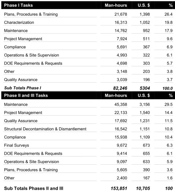
The man-hours devoted to major project tasks for Phases I - III are listed in Table 4-2. Note that the time required to characterize the facility was greater than the time devoted to actually dismantling the HCF.
Table 4-2 HCF Distribution of Man-Hours Expended and Related Costs (1,000s, US$1998)
Phase I Tasks Man-hours U.S. $ %
Plans, Procedures & Training 21,678 1,398 26.4 Characterization 16,313 1,052 19.8 Maintenance 14,762 952 17.9 Project Management 7,924 511 9.6 Compliance 5,691 367 6.9 Operations & Site Supervision 4,993 322 6.1 DOE Requirements & Requests 4,698 303 5.7
Other 3,148 203 3.8
Quality Assurance 3,039 196 3.7
Sub Totals Phase I 82,246 5304 100.0
Phase II and III Tasks Man-hours U.S. $ %
Maintenance 45,358 3,156 29.5 Project Management 22,133 1,540 14.4 Quality Assurance 17,692 1,231 11.5 Structural Decontamination & Dismantlement 16,542 1,151 10.8 Compliance 15,938 1,109 10.4 Final Surveys 9,672 673 6.3 DOE Requirements & Requests 9,414 655 6.1 Operations & Site Supervision 9,097 633 5.9 Plans, Procedures & Training 5,605 390 3.6
Other 2,400 167 1.6
Sub Totals Phases II and III 153,851 10,705 100
4.1.3
Waste Handling and Disposal
Section 3.3 and Table 3-1 provide detailed information regarding the disposition of the waste forms generated from the HCF project. Table 4-3 provides the cost of packaging, transportation and disposing of the waste forms. The cost per truck shipment to the
Hanford Site and NTS in 1998 money value was about $2,340 and $630, respectively. This is based on a rate of $1.0536 per kilometre. There were a total of 301 and 100 shipments respectively to the Hanford Site and NTS; therefore, the costs of truck transportation to the Hanford Site and NTS were $704,340 and $63,000, respectively. Table 4-3 Waste Volumes (m3) and Costs of Packaging, Transportation and Disposal for All Waste
Forms Excluding Non-Active Waste (1,000s, US$1998)
Waste Form Waste Type Quantity
(m3) Disposal $ per m3 Total $ per m3 U.S. $ Concrete and
building debris
and equipment LLW 2,674.20 1,557.37 2,263.85 6,054.0 Soil and Asphalt to
Envirocare
Radioactive
particles in soil 1,713.86 619.77 781.39 1,339.2
Soil to NTS
Radioactive
particles in soil 1,632.73 not available 463.90 757.4 Debris including
contaminated Pb Mixed 13.76 not available 26,958.17 371.0
The shipments to Envirocare involved intermodal (truck and train) transport and the costs were not specified separately.
4.2
Derived Benchmarking Results
As mentioned previously, the HCF decommissioning project costs were highly
influenced by the requirements of U.S. government funding; therefore, there are a limited number of meaningful benchmarks that can be derived for application to other projects. The preceding quantitative information in this section has been used to derive unit costs for specific project categories. Section 4.1.3 outlines unit costs suitable for benchmarking waste disposition. This section briefly addresses benchmarking for other tasks.
4.2.1 Characterization
As indicated in Table 4-1, the total cost for Phase I was $11.788 million while the cost of characterization was only 8.9 percent of this total. The characterization task included the collection of samples, analyzing the samples and writing a characterization report. The cost of characterization was $1.052 million and required about 16,300 hours. This however is probably a misleading number in terms of benchmarking and requires adjustment for comparison with other projects, for the following reasons.