INTRODUCTION
Additive manufacturing (AM) technologies such as rapid prototyping, more commonly known as three-dimensional (3D) printing, is an increasingly used technology for dental applications. Two of the most common applications for 3D printing using polymeric materials are dental models and biocompatible surgical guides, which facilitate the planning and manufacturing of dental restorations1-5). Since high accuracy of implant placement and fit of a dental restoration are crucial for the patient treatment and outcome, surgical guides and models manufactured by printing needs to be investigated to ensure that they are comparable to those manufactured by traditional technologies3,6-8).
According to The American Section of the International Association for Testing Materials (ASTM), AM technologies can be divided into seven categories where stereolithography (SLA), including digital light processing (DLP), represents one9). SLA and DLP are technologies commonly used for printing 3D objects of polymeric materials, and the technologies have several similarities2,10-13). The 3D object is built layer by layer by immersing a build platform in a resin tank consisting of liquid light-cured resin, i.e., photopolymers. The key difference between the technologies is the type of light source: SLA using an ultraviolet (UV) laser light to draw a pattern of a cross-section of the 3D object, and DLP using a digital light projector screen to project the entire cross-section of the 3D object at once. DLP is based on micro-electro-mechanical technology using a chip containing microscopic mirrors moveable in two directions, a so-called digital micromirror device (DMD)10). The number of pixels defines the resolution of the polymerized mask10,12). Resolution is the finest feature a 3D printer can produce and should not be confused
with accuracy when evaluating the results of 3D printed objects. According to ISO14,15) accuracy consists of trueness and precision. Trueness is defined as the closeness of agreement between measurements (arithmetic mean) and the true value and precision as the closeness of agreement between repeated measurements. In terms of dental models and surgical guides, the trueness can be described as how close the measurements of the printed object are to the CAD model’s dimensions and the precision how close the measurements of repeatedly printed similar objects are to each other.
The accuracy of dental models and surgical guides can be influenced by different factors such as the type of AM technology and manufacturer2,6,8,16-19) as well as the type of material, layer thickness2,16,17,20) depth of cure2,11,12), build orientation i.e. build direction and angle7,10,21-23), platform position7,10) amount of support structures7,10,23) and the post-processing procedure2,7,10-12,24). In the literature, and in addition to these factors, the test set-up tend to differ, making a comparison between results of studies and general conclusions difficult. In comparison to traditional stone and milled models, studies4,18,19,25,26) have shown that 3D printed models using different types of AM technologies might have sufficient accuracy for selected orthodontic applications, although not always having higher accuracy than stone models4,8,19). However, for prosthodontic applications the accuracy might not be clinically acceptable, and further research is needed4,18). Zhang et al.16) compared the accuracy of 3D printed dental models using DLP and SLA technologies and different layer thicknesses, and generally, the accuracy increased with decreasing layer thickness. The DLP technology showed higher accuracy than SLA at a layer thickness of 100 µm, and the optimal layer thickness for DLP technology was 50 µm. The absolute average deviations
Accuracy of 3D printed polymers intended for models and surgical guides
printed with two different 3D printers
Camilla JOHANSSON, Jasmin DIBES, Luis Emilio LÓPEZ RODRIGUEZ and Evaggelia PAPIA
Department of Materials Science and Technology/Futurum Innovation, Faculty of Odontology, Malmö University, SE-205 06 Malmö, Sweden Corresponding author, Camilla JOHANSSON; E-mail: camilla.johansson@mau.se
The purpose of the study was to evaluate the accuracy: trueness and precision of photopolymers used for dental models and surgical guides printed with two different digital light processing (DLP) printers. Forty specimens of four materials; E-dentstone®, E-shell®,
NextDent™ Model, NextDent™ SG, and two designs; models A and B (n=5), were manufactured (DDDP, EvoDent). Trueness was evaluated by comparing values for 26 parameters with the CAD models’ reference values and precision through standard deviation. The trueness and precision were higher for linear than for angle parameters. X- and Y-axes showed higher trueness than Z-axis and model B higher trueness than model A. The conclusions are; the accuracy is dependent on the design of the object. The linear precision appears to be high. The highest trueness was observed for a surgical guide polymer (NextDent™ SG). The definition of clinically relevant accuracy and acceptable production tolerance should be evaluated in future studies.
Keywords: Additive manufacturing, 3D printing, Digital light processing, Dental models, Surgical guides
Received Feb 10, 2020: Accepted Apr 27, 2020
for most groups were smaller than 0.05 mm, assessed as clinical acceptable for orthodontic applications16).
Previous reviews27,28) have indicated smaller deviations between the planned and postoperative implant position when using surgical guides, i.e., guided implant surgery, which is consistent with the recommendations from the European Association of Osseointegration (EAO) consensus conference29). However, it is also emphasized that only limited data is available, and the evidence is scarce. Hence, further studies are needed. Accordingly, the number of studies analyzing the accuracy of the actual 3D printed surgical guides is also limited. Gjelvold et al.24) evaluated the accuracy of 3D printed surgical guides manufactured with SLA and DLP technologies and concluded that the final implant position deviations were similar for both technologies.
Most studies have made comparisons of the accuracy of materials for the same application with different printers or printing techniques. However, there can be differences in the accuracy between materials with different applications manufactured in the same printer since layer thickness, activation range wavelength, shrinkage, and translucency differ between materials11,12).
The purpose of the study was to evaluate the accuracy: trueness and precision of photopolymers used for dental models and surgical guides printed with two different DLP printers.
The null hypothesis was that there are no differences in accuracy between the different materials because the DLP technology produces a high accuracy regardless of material.
MATERIALS AND METHODS
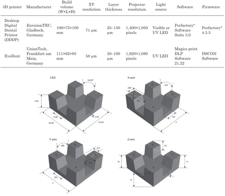
A total of 40 specimens were manufactured in two different DLP 3D printers; 20 were printed in DDDP (EnvisionTEC, Gladbeck, Germany) and 20 in EvoDent (UnionTech, Frankfurt am Main, Germany) (Tables 1 and 2). The respective 20 specimens were divided into four groups (n=10) depending on the material and subsequently divided into subgroups (n=5) depending on the type of model. The specimens were as a die for an inlay (model A) and a model with two abutments for a four-unit fixed dental prosthesis, FDP (model B), according to ISO 12836:2015 Annex A and B15) and modified by Braian et al.17) (Figs. 1 and 2).
Two CAD models representing model A and B17) with an edge radius of 0.01 mm were used (Solidworks educational edition 2013, Dassault Systèmes SE, Vélizy-Villacoublay, France). The dimensions of the CAD models were used as reference values for the upcoming measurements to evaluate the accuracy of the printed specimens (Table 3). The dimensions of the CAD models were controlled using Magics print DLP 21.22 (Materialise, Leuven, Belgium) and 3Shape Dental System (3Shape, Copenhagen, Denmark). Standard tessellation language (STL) files with the solid CAD models were exported to the printers. The mesh of model
A consisted of 60 triangles and 32 vertices and model B of 5,800 triangles and 2,902 vertices with mesh density 128 and cell size 0.112 mm. Each CAD model was centrally placed directly onto the build platform without support structures using the software Perfactory® Software Suite 3.0 (EnvisionTEC, Marl, Germany) for DDDP and Magics print DLP 21.22 (Materialise) for EvoDent. The specimens were printed at room temperature of 23±1°C and post-processed one at the time according to the manufacturers’ recommendations. The surgical guide materials used in the study are biocompatible. NextDent™ SG is a CE-certified Class I material and E-shell® a CE-certified Class IIa material and USP Plastic Class VI.
Manufacturing of specimens of E-Dentstone® and
E-Shell® in DDDP
Build styles corresponding to the respective material, E-Dentstone® and E-Shell® were chosen in Perfactory® Software Suite 3.0. The layer thickness for E-Dentstone® was 50 µm and 100 µm for E-Shell®. The light source of the 3D printer was calibrated, and when changing material, the mask was regenerated according to the manufacturer’s instructions. The projector brightness was set to 180 mW/dm2 for E-Dentstone® and 230 mW/dm2 for E-Shell®. The specimen was removed from the build platform with a chisel blade (UnionTech) and cleaned with isopropyl alcohol (IPA) 99.5% (Isopropanol Pro Analysis, Solveco AB, Rosersberg, Sweden, Lot 6091549) in three steps. The specimens made of E-Dentstone® were cleaned in a cleaning device (Form Wash, Formlabs, Somerville, MA, USA) for four minutes in two steps and air blasted for 10 s between the steps. The specimens made of E-Shell® were cleaned in the same way for two minutes in the respective step. As the last step, the specimens made of E-Dentstone® and E-Shell® were cleaned with fresh IPA in an ultrasonic bath (BioSonic UC100XD, Coltene Whaledent, Altstätten, Switzerland) for two minutes and one minute respectively according to the manufacturer’s recommendations, followed by air blasting for 10 s. The specimens made of E-Dentstone® were subjected to a drying process in an incubator at 37°C for 30 min. Final polymerization of the specimens was carried out in a post-curing unit (Otoflash G171, EnvisionTEC) with 2×300 flashes for E-Dentstone® and 2×1,000 flashes for E-Shell® according to the manufacturer’s instructions.
Manufacturing of specimens of NextDent™ Model and NextDent™ SG in EvoDent
The layer thickness for NextDent™ Model was set to 50 µm and 100 µm for NextDent™ SG according to the manufacturer’s instructions. The STL file of each CAD model was prepared in Magics print DLP 21.22 and uploaded as a .utk file (building file format) to the printer (EvoDent). The specimen was removed and cleaned (Form Wash) as previously mentioned in one step for 10 min, followed by air blasting for 10 s. Each specimen was placed in a water-filled glass container in a post-curing unit (EvoDent Post Curing Unit, UnionTech) for 10 min,
Table 1 Overview of the groups and materials used 3D
printer Material Material composition Indication Model A (n) Model B (n) Abbreviation of the group
Material manufacturer, Lot No. DDDPa E-Dentstone® Peach Acrylated monomer 30–70%, Acrylated oligomer 10–20%, 1,6-hexandioldiakrylat 1–3%, Titanium Dioxide 0.1–0.2% Models 5 EMA EnvisionTEC, Gladbeck, Germany, 020718 DDDPa E-Dentstone® Peach Acrylated monomer 30–70%, Acrylated oligomer 10–20%, 1,6-hexandioldiakrylat 1–3%, Titanium Dioxide 0.1–0.2%
Models 5 EMB EnvisionTEC, 020718
DDDPa E-Shell® 600c Tetrahydrofurfuryl methacrylate 10–25%, 7,7,9- Trimethyl-4,13-dioxo-3,14- dioxa-5,12-diaza-hexadecan-1,16-diol dimethacrylate 5–20%, Diphenyl(2,4,6-trimethylbenzoyl)phosphine oxide <1% Surgical Guides 5 ESA EnvisionTEC, 180415 DDDPa E-Shell® 600c Tetrahydrofurfuryl methacrylate 10–25%, 7,7,9- Trimethyl-4,13-dioxo-3,14- dioxa-5,12-diaza-hexadecan-1,16-diol dimethacrylate 5–20%, Diphenyl(2,4,6-trimethylbenzoyl)phosphine oxide <1% Surgical
Guides 5 ESB EnvisionTEC, 180415
EvoDentb NextDent™ Model Monomer based on methacrylic ester: methacrylic oligomers >90%, Phosphine oxides <3%, colorants and pigments
Models 5 NMA Vertex-Dental, Soesterberg, The Netherlands, n.a. EvoDentb NextDent™ Model Monomer based on methacrylic ester: methacrylic oligomers >90%, Phosphine oxides <3%, colorants and pigments
Models 5 NMB Vertex-Dental, n.a.
EvoDentb NextDent™ SGd Monomer based on methacrylic ester: methacrylic oligomers >90%, Phosphine oxides <3%, colorants and pigments
Surgical Guides 5 NSA Vertex-Dental, n.a. EvoDentb NextDent™ SGd Monomer based on methacrylic ester: methacrylic oligomers >90%, Phosphine oxides <3%, colorants and pigments
Surgical
Guides 5 NSB
Vertex-Dental, n.a.
EMA: E-Dentstone Model Model A, EMB: E-Dentstone Model Model B, ESA: E-Shell Surgical Guide Model A, ESB: E-Shell Surgical Guide Model B, NMA: NextDent Model Model A, NMB: NextDent Model Model B, NSA: NextDent Surgical Guide Model A, NSB: NextDent Surgical Guide Model B, aManufacturer: EnvisionTEC, Gladbeck, Germany, bManufacturer: UnionTech, Frankfurt am Main, Germany, cCE-certified Class IIa material, dCE-certified Class I material
Fig. 1 Model A designed as a die for an inlay.
The CAD figure shows the dimensions (mm/degrees) of the parameters evaluated and X-, Y- and Z-axes the different parameters.
Table 2 Specifications of the 3D printers used 3D printer Manufacturer Build volume (W×L×H) XY resolution Layer thickness Projector resolution Light
source Software Firmware
Desktop Digital Dental Printer (DDDP) EnvisionTEC, Gladbeck, Germany 100×75×100 mm 71 µm 25–150 µm 1,400×1,050 pixels Visible or UV LED Perfactory® Software Suite 3.0 Perfactory® 4.5.5 EvoDent UnionTech, Frankfurt am Main, Germany 111×62×85 mm 58 µm 50–100 µm 1,920×1,080 pixels UV LED Magics print DLP Software 21.22 DSCON Software
followed by air blasting according to the manufacturer’s instructions. All specimens were stored in a sealed container at room temperature until the measurements were performed.
Measurements of trueness and precision
The measurements of each printed specimen were performed 30 min after completed post-curing by one operator. The parameters evaluated were divided into two horizontal axes; X and Y, one vertical axis; Z and angles; a (Figs. 1 and 2, Table 3). For model A, 15 parameters were evaluated, and for model B, 11 parameters were evaluated. The linear parameters were measured with a
digital caliper (DIGI-MET 2212216, HOREX®, Preisser, Gammertingen, Germany) with a precision of 0.01 mm. The measurements were standardized by placing the caliper at the edges of the specimens, as indicated by the arrows in Figs. 1 and 2. The angle parameters (aac, aba, acd, adb, al and ar) were measured and processed with a digital light microscope (WILD M7A, Wild Heerbrugg/WILD MZ6, Leica Application Suite, Version 4.1.0 Build: 1264/Camera Leica DFC 420, Leica Microsystems, Heerbrugg, Switzerland). A putty mold for each model was used to standardize the position and the measurements of the specimens.
Fig. 2 Model B designed as a model for a four-unit FDP.
The CAD figure shows the dimensions (mm/degrees) of the parameters evaluated and X-, Y- and Z-axes the different parameters. l: left, r: right Table 3 Parameters and dimensions (mm/degrees) of model A and B
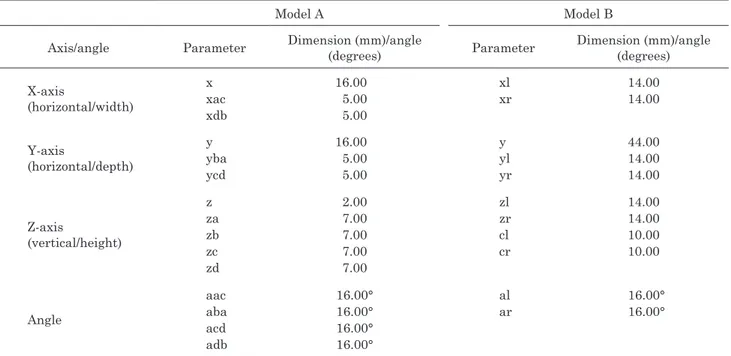
Model A Model B
Axis/angle Parameter Dimension (mm)/angle (degrees) Parameter Dimension (mm)/angle (degrees) X-axis (horizontal/width) x xac xdb 16.00 5.00 5.00 xl xr 14.00 14.00 Y-axis (horizontal/depth) y yba ycd 16.00 5.00 5.00 y yl yr 44.00 14.00 14.00 Z-axis (vertical/height) z za zb zc zd 2.00 7.00 7.00 7.00 7.00 zl zr cl cr 14.00 14.00 10.00 10.00 Angle aac aba acd adb 16.00° 16.00° 16.00° 16.00° al ar 16.00° 16.00°
l: left, r: right, c: cone
arithmetic mean and standard deviation of each group of the respective parameter were calculated. The trueness was evaluated by comparing the values of the groups
for the respective parameter with the CAD models’ reference values. The precision was evaluated through the standard deviation of the groups of the respective
Table 5 The results of the trueness and precision (mm/degrees): arithmetic mean and standard deviation (±SD) of the groups and the reference values for each parameter for model B
Group Parameters xl xr y yl yr zl zr cl cr al ar Ref. 14.00 14.00 44.00 14.00 14.00 14.00 14.00 10.00 10.00 16.00 16.00 EMB MeanSD (0.04)14.03 (0.03)14.00 43.90(0.08) (0.04)14.05 (0.03)14.00 (0.03)14.41 14.40(0.02) (0.03)10.03 (0.02)10.01 (0.18)15.88 16.06(0.16) ESB Mean SD 14.05 (0.02) 14.05 (0.02) 44.01 (0.04) 14.06 (0.07) 14.07 (0.06) 13.56 (0.09) 13.84 (0.06) 10.09 (0.06) 9.98 (0.02) 16.14 (0.33) 16.44 (1.98) NMB Mean SD 14.01 (0.01) 14.04 (0.01) 43.95 (0.05) 14.00 (0.01) 13.99 (0.01) 13.83 (0.21) 13.78 (0.19) 9.95 (0.08) 9.96 (0.07) 15.22 (0.17) 16.25 (0.15) NSB Mean SD 14.03 (0.02) 14.02 (0.02) 44.00 (0.02) 14.02 (0.01) 14.01 (0.02) 13.88 (0.06) 13.87 (0.05) 9.95 (0.07) 9.95 (0.06) 16.03 (0.25) 16.06 (0.18) Ref.: The reference value of the CAD model for the parameter, SD: Standard deviation
Table 4 The results of the trueness and precision (mm/degrees): arithmetic mean and standard deviation (±SD) of the groups and the reference values for each parameter for model A
Group
Parameters
x xac xdb y yba ycd z za zb zc zd aac aba acd adb
Ref. 16.00 5.00 5.00 16.00 5.00 5.00 2.00 7.00 7.00 7.00 7.00 16.00 16.00 16.00 16.00 EMA MeanSD (0.02)15.95 (0.03)5.04 (0.05)5.03 15.97(0.03) (0.03)5.00 (0.04)5.03 (0.01)2.48 (0.02)7.43 (0.01)7.45 (0.02)7.44 (0.02)7.43 15.22(0.36) (0.55)15.09 15.06(0.36) (0.32)15.57 ESA MeanSD (0.02)15.92 (0.03)5.03 (0.02)5.03 15.91(0.01) (0.06)5.04 (0.05)5.02 (0.06)1.82 (0.07)6.77 (0.07)6.76 (0.05)6.78 (0.06)6.80 15.06(0.48) (0.54)14.83 15.07(0.56) (0.62)14.47 NMA Mean SD 15.93 (0.04) 5.02 (0.04) 5.00 (0.07) 15.95 (0.03) 5.05 (0.04) 5.04 (0.02) 1.65 (0.25) 6.66 (0.19) 6.59 (0.27) 6.62 (0.22) 6.61 (0.26) 15.22 (0.48) 15.29 (0.44) 15.21 (0.48) 15.27 (0.36) NSA Mean SD 15.99 (0.01) 5.01 (0.05) 5.01 (0.03) 15.96 (0.01) 4.95 (0.10) 5.01 (0.03) 1.89 (0.05) 6.95 (0.01) 6.94 (0.02) 6.95 (0.03) 6.95 (0.03) 15.14 (0.55) 14.74 (0.64) 15.41 (0.44) 15.42 (0.53) Ref.: The reference value of the CAD model for the parameter, SD: Standard deviation
parameter. Statistical analysis
One-way ANOVA, Tukey’s test was used to determine differences in trueness between the groups and the reference values (IBM SPSS Statistics 25, SPSS, Chicago, IL, USA). The level of significance was set to α=0.05.
RESULTS
The results of the measurements of the groups, along with the reference values for each parameter for models A and B are shown in Tables 4 and 5. The precision is
shown through the standard deviation of the groups of the respective parameter. The trueness and precision were generally higher for the linear parameters than for the angle parameters.
The trueness is displayed through the differences between the values of the groups for the respective parameter and the CAD models’ reference values, Tables 6 and 7. The X- and Y-axes showed higher trueness than the Z-axis and model B higher trueness in comparison to model A. The trueness of the groups significantly differed from the reference values for a majority of the parameters. Based on the statistical analysis NSA and NSB showed the highest trueness.
Table 6 Trueness (mm/degrees) for model A of the groups for each parameter
Group Parameters
x xac xdb y yba ycd z za zb zc zd aac aba acd adb
EMA −0.05* 0.04* 0.03 −0.03* 0.00 0.03* 0.48* 0.43* 0.44* 0.44* 0.43* −0.78* −0.91* −0.94* −0.43* ESA 0.08* 0.03* 0.03* −0.09* 0.04 0.02* −0.18* −0.23* −0.24* −0.22* −0.20* −0.94* −1.17* −0.93* −1.26* NMA −0.07* 0.02 0.00 −0.05* 0.05* 0.04* −0.35* −0.34* −0.41* −0.38* −0.39* −0.78* −0.71* −0.79* −0.73* NSA −0.01 0.01 0.01 −0.04* −0.05* 0.01 −0.11* −0.05 −0.06 −0.05 −0.05 −0.86* −1.26* −0.59* −0.58* Values denoted by * indicate a significant difference (p≤0.05) from the reference value.
Table 7 Trueness (mm/degrees) for model B of the groups for each parameter
Group Parameters xl xr y yl yr zl zr cl cr al ar EMB 0.03* 0.00 −0.10* 0.05* 0.00 0.41* 0.40* 0.03 0.01 −0.12 0.06 ESB 0.05* 0.05* 0.01 0.06* 0.07* −0.04* −0.16* 0.09* −0.02 0.14 0.44 NMB 0.01 0.04* −0.05* 0.00 −0.01 −0.17* −0.22* −0.05* −0.04* −0.78* 0.25 NSB 0.03* 0.02* 0.00 0.02 0.01 −0.12* −0.13* −0.05* −0.05 0.03 0.06
Values denoted by * indicate a significant difference (p≤0.05) from the reference value.
DISCUSSION
Providing surgical guides for implant placement positioning and dental models with a high accuracy are prerequisites for successful patient treatment. When implementing new technologies and materials in the treatment process, it is crucial to have knowledge about the trueness and precision of the products manufactured. In the absence of an ISO standard for assessing the accuracy of 3D printed objects, the study was based on the ISO standard 12836:2015, aiming to assess the accuracy of digitizing devices for CAD/CAM systems15).
It is recommended to use at least two of the three specimens described15). Hence, following a previous study17), the two dental geometries (model A and model B) were included in the study since considered more clinically relevant than the technical sphere-shaped specimen. Using ISO definitions of accuracy and standardized digital specimens can increase the likelihood of repeating the measurements with high reliability and facilitate comparisons of results. When the accuracy of standardized specimens has been validated, more complex geometries can subsequently be investigated.
The number of specimens for the respective material was based on previous studies6,17). Because the light intensity can vary across the build platform, thus possibly affecting the accuracy, the objects were printed one at the time centrally placed on the platform. This approach is supported by Unkovskiy et al.7) that
showed that the accuracy was higher in the central part of the platform, consequently emphasizing a central placement of specimens in further research, allowing accurate comparisons. Generally, the entire platform is utilized, and further research should address how the accuracy is affected by the placement on the platform. To adhere the object to the platform the initial layer might require higher exposure time or layer thickness depending on the technology and manufacturer2,7,10). The manufacturers’ recommendations for the initial layer settings were consequently followed to avoid detachment or distortion of the specimens due to inadequate adhesion. For DDDP, the layer thickness was 0.4 mm, and for EvoDent, approximately 0.7–1.2 mm, depending on the tightening of the platform. Because the thickness varied and higher exposure time of the initial layer might cause compression, it could not be taken into account in the calculations in the Z-dimensions. Moreover, when removing objects printed directly on the platform, there is an imminent risk of dimensionally affecting the object in the Z-axis due to strong adhesion. Hence, the accuracy is not correctly represented. This assumption is evident in the results, which show lower trueness in the Z-axis, and in accordance with previous studies7,20). In the clinical situation, the additional initial layer thickness is though not crucial for the accuracy of the coronal part of a model or for surgical guides that are printed either with support structures or with an additional horizontal part towards the platform. Furthermore, the values of the Z-axis parameters were similar within the respective
group in the present study, enabling modifications of the software settings to compensate for the deviations and increase the trueness.
The trueness of the groups significantly differed from the reference values for a majority of the parameters; hence, the null hypothesis can be rejected. Regarding the linear parameters, all trueness values were <0.5 mm and in the X- and Y-axes, the majority were <0.05 mm. Previous studies have shown similar results with a trueness of <0.1 mm17) and <0.06 mm16), although the results are not directly comparable due to different study designs, technologies, materials, and settings. Previous studies have also not made statistical comparisons between groups16,17). The trueness and precision were generally higher for the linear parameters than for the angle parameters, especially for model A, following the results from Braian et al.17) where lower trueness was displayed for model A for the angle parameters. These results may be partly because the method used for the angle measurements is more complex, thus it is more difficult to achieve high reliability and that the geometry is negative. Furthermore, model B overall showed higher trueness compared to model A, possibly caused by the different geometries and complexity degrees.
There is no consensus concerning clinically relevant and acceptable values for the accuracy of models and surgical guides30). According to the ISO standard 6873, the acceptable discrepancy of type IV stone models is 0.05 mm31). An accuracy of 0.2–0.5 mm has been proposed as clinically acceptable in some studies6,16,18,19), and others have proposed an accuracy of <0.2 mm because it is consistent with the reliability of the manual measurement itself18). Consequently, the results of the study concerning the linear parameters for trueness are in the range of what can be considered as a clinically acceptable accuracy for models.
Overall, the material NextDent™ SG (NSA, NSB) showed the highest trueness. One reason might be that the translucency of the material favors the depth of cure since pigments and dyes can inhibit the light from passing through the material2,10). Pixilation, i.e., small areas with a lower degree of polymerization due to shadows between each pixel, associated with the DLP technology, might enhance the effect. Following the results of the present study, Zhang et al.16) also achieved the highest accuracy with the EvoDent printer, although the groups were not compared statistically. Because the platform is moving in the Z-direction, potentially increasing the risk of repositioning biases, finer layer thicknesses can result in reduced accuracy. Accordingly, a layer thickness of 50 µm, as for the model materials, implies twice as many repositionings of the platform as the surgical guide materials of 100 µm. NextDent™ SG is in comparison to E-Shell® translucent but dyed, partly explaining the differences between the groups. Zhang et al.16) contradictory concluded that the accuracy was slightly higher with a layer thickness of 50 µm compared to 100 µm, when using similar printers (UnionTec EvoDent and EnvisionTec Vida HD) and model materials
(Model Ortho and E-Dentstone).
CONCLUSIONS
Within the limitations of this in-vitro study, the following conclusions regarding 3D printed polymers indicated for dental models and surgical guides can be drawn:
• The accuracy is dependent on the design of the object.
• The linear precision appears to be high.
• The highest trueness was observed for a surgical guide polymer (NextDent™ SG).
• The definition of clinically relevant accuracy and acceptable production tolerance should be evaluated in future studies.
ACKNOWLEDGMENTS
The authors would like to thank Michael Braian for kindly providing the CAD models and EnvisionTEC GmbH for generously supplying materials.
REFERENCES
1) Martelli N, Serrano C, van den Brink H, Pineau J, Prognon P, Borget I, et al. Advantages and disadvantages of 3-dimensional printing in surgery: A systematic review. Surgery 2016; 159: 1485-1500.
2) Stansbury JW, Idacavage MJ. 3D printing with polymers: Challenges among expanding options and opportunities. Dent Mater 2016; 32: 54-64.
3) Jang Y, Sim JY, Park JK, Kim WC, Kim HY, Kim JH. Evaluation of the marginal and internal fit of a single crown fabricated based on a three-dimensional printed model. J Adv Prosthodont 2018; 10: 367-373.
4) Jang Y, Sim JY, Park JK, Kim WC, Kim HY, Kim JH. Accuracy of 3-unit fixed dental prostheses fabricated on 3D-printed casts. J Prosthet Dent 2020; 123: 135-142.
5) Li C, Cheung TF, Fan VC, Sin KM, Wong CW, Leung GK. Applications of three-dimensional printing in surgery. Surg Innov 2017; 24: 82-88.
6) Kim SY, Shin YS, Jung HD, Hwang CJ, Baik HS, Cha JY. Precision and trueness of dental models manufactured with different 3-dimensional printing techniques. Am J Orthod Dentofacial Orthop 2018; 153: 144-153.
7) Unkovskiy A, Bui PH, Schille C, Geis-Gerstorfer J, Huettig F, Spintzyk S. Objects build orientation, positioning, and curing influence dimensional accuracy and flexural properties of stereolithographically printed resin. Dent Mater 2018; 34: e32-e333.
8) Park ME, Shin SY. Three-dimensional comparative study on the accuracy and reproducibility of dental casts fabricated by 3D printers. J Prosthet Dent 2018; 119: 861.e-861.e7. 9) International Organization for Standardization. ISO/ASTM
52900: 2015. Additive Manufacturing —General Principles— Terminology. Geneva: International Organization for Standardization; 2015.
10) Monzon M, Ortega Z, Hernandez A, Paz R, Ortega F. Anisotropy of photopolymer parts made by digital light processing. Materials 2017; 10: 64.
11) Revilla-Leon M, Meyers MJ, Zandinejad A, Ozcan M. A review on chemical composition, mechanical properties, and manufacturing work flow of additively manufactured current polymers for interim dental restorations. J Esthet Restor Dent 2019; 31: 51-57.
used for processing polymers: Current status and potential application in prosthetic dentistry. J Prosthodont 2019; 28: 146-158.
13) Hornbeck L. Spatial light modulator and method. Patent Number 5,061,049. United States Patent; 1991.
14) International Organization for Standardization. ISO 5725-1: 1994. Accuracy (trueness and precision) of measurement methods and results — Part 1: General principles and definitions. Geneva: International Organization for Standardization; 1994.
15) International Organization for Standardization. ISO 12836: 2015. Dentistry —Digitizing devices for CAD/CAM systems for indirect dental restorations— Test methods for assessing accuracy. Geneva: International Organization for Standardization; 2015.
16) Zhang ZC, Li PL, Chu FT, Shen G. Influence of the three-dimensional printing technique and printing layer thickness on model accuracy. J Orofac Orthop 2019; 80: 194-204. 17) Braian M, Jimbo R, Wennerberg A. Production tolerance
of additive manufactured polymeric objects for clinical applications. Dent Mater 2016; 32: 853-861.
18) Hazeveld A, Huddleston Slater JJ, Ren Y. Accuracy and reproducibility of dental replica models reconstructed by different rapid prototyping techniques. Am J Orthod Dentofacial Orthop 2014; 145: 108-115.
19) Rebong RE, Stewart KT, Utreja A, Ghoneima AA. Accuracy of three-dimensional dental resin models created by fused deposition modeling, stereolithography, and Polyjet prototype technologies: A comparative study. Angle Orthod 2018; 88: 363-369.
20) Braian M, Jonsson D, Kevci M, Wennerberg A. Geometrical accuracy of metallic objects produced with additive or subtractive manufacturing: A comparative in vitro study. Dent Mater 2018; 34: 978-993.
21) Ide Y, Nayar S, Logan H, Gallagher B, Wolfaardt J. The effect of the angle of acuteness of additive manufactured models and the direction of printing on the dimensional fidelity: clinical implications. Odontology 2017; 105: 108-115.
22) Osman RB, Alharbi N, Wismeijer D. Build angle: Does it influence the accuracy of 3D-printed dental restorations
using digital light-processing technology? Int J Prosthodont 2017; 30: 182-188.
23) Alharbi N, Osman RB, Wismeijer D. Factors influencing the dimensional accuracy of 3D-printed full-coverage dental restorations using stereolithography technology. Int J Prosthodont 2016; 29: 503-510.
24) Gjelvold B, Mahmood DJH, Wennerberg A. Accuracy of surgical guides from 2 different desktop 3D printers for computed tomography-guided surgery. J Prosthet Dent 2019; 121: 498-503.
25) Koretsi V, Kirschbauer C, Proff P, Kirschneck C. Reliability and intra-examiner agreement of orthodontic model analysis with a digital caliper on plaster and printed dental models. Clin Oral Investig 2019; 23: 3387-3396.
26) Jeong YG, Lee WS, Lee KB. Accuracy evaluation of dental models manufactured by CAD/CAM milling method and 3D printing method. J Adv Prosthodont 2018; 10: 245-251. 27) D’haese J, Van De Velde T, Komiyama A, Hultin M, De Bruyn
H. Accuracy and complications using computer-designed stereolithographic surgical guides for oral rehabilitation by means of dental implants: a review of the literature. Clin Implant Dent Relat Res 2012; 14: 321-335.
28) Tahmaseb A, Wismeijer D, Coucke W, Derksen W. Computer technology applications in surgical implant dentistry: a systematic review. Int J Oral Maxillofac Implants 2014; 29 Suppl: 25-42.
29) Hämmerle CH, Cordaro L, van Assche N, Benic GI, Bornstein M, Gamper F, et al. Digital technologies to support planning, treatment, and fabrication processes and outcome assessments in implant dentistry. Summary and consensus statements. The 4th EAO consensus conference 2015. Clin Oral Implants Res 2015; 26 Suppl 11: 97-101.
30) Sicilia A, Botticelli D; Working Group 3. Computer-guided implant therapy and soft- and hard-tissue aspects. The Third EAO Consensus Conference 2012. Clin Oral Implants Res 2012; 23 Suppl 6: 157-161.
31) International Organization for Standardization. ISO 6873:2013 Dentistry —Gypsum products. 3rd ed. Geneva: