Technology and Society Department of Computer Science
Bachelor thesis - Winter 2016 within
Bachelor of Science in Engineering in Computer Science
and
Program development
Bachelor thesis report March 4, 2016
Fair Medium Access Control Mechanism Reducing Throughput
Degradation in IEEE 802.11s Wireless Mesh Networks
Rättvis Medie-åtkomstkontroll mekanism för minskande av genomströmningsreduktion i IEEE
802.11s Trådlöst Mesh Nätverk
Supervisor:
Ivan Kruzela
This work is done in cooperation with:
Written by:
Saeed Mir Ghasemi
(SMG)
Haisam El-Hajj Moussa
(HEM)I
Abstract
This thesis rapport deals with the performance issues of the newly standardized Wireless mesh protocol (IEEE 802.11s). In this thesis, we work on improving the conditions that results in throughput degradation in a chain of nodes topology. The mesh standard is very promising with many advantages for both IoT systems and home wireless networks.
We work on the issue of unfairness when CSMA/CA is applied, which causes throughput degradation due to packet loss and indicates starvation. We analyze the implication of the Collision Avoidance (CA) mechanism and propose a replacement for the CA that is both fair and able to maintain collision avoidance. We implement this in a simulator and the result shows significantly higher end-to-end throughput compared to the original CSMA/CA and no packet loss due to buffer overflow.
Keywords: throughput degradation – contention based – multi-hop – distributed medium access control – IEEE 802.11s – mesh networking – inter-node fairness – Collision avoidance – Greedy sender – buffer overflow – two-hop interference
II
Sammanfattning
Denna rapport behandlar prestandaproblem i den nyligen standardiserade Mesh kommunikationsstandarden (IEEE 802.11s). I denna rapport, undersöker och förbättra vi ett förhållande som resulterar i reduktion av genomströmningen i en kedja av noder topologi. IEEE802.11s är mycket lovande med många fördelar för både IoT-systemen och trådlösa nätverk i båda hemmet och arbete.
Vi arbetar med frågan om orättvisa när CSMA/CA tillämpas, vilket orsakar genomströmningsreduktion på grund av paketförluster och indikerar svältning. Vi analyserar konsekvenserna av Collision Avoidance (CA) mekanism och föreslår en ersättning för CA som är både rättvist och samtidigt kan upprätthålla undvikande av kollisioner. Vi implementera detta i en simulator och resultatet visar på betydligt högre end-to-end-genomströmning än standard CSMA/CA och inga paketförluster på grund av buffertspill.
III
Acknowledgement
We would like to thank everyone at TerraNet for the great hospitality and for making this thesis possible. In particular, we want to express our thanks to Johan Petersen and Monthadar Al Jaberi for their invaluable feedback during evaluations and discussions.
Foremost, we would like to express our deepest gratitude to our friend and mentor, Ivan Kruzela, for his great support and guidance in writing this thesis.
IV
Contents
1 Introduction ... 1
1.1 Background ... 1
1.2 Area of work ... 1
1.3 Why mesh networking? ... 2
1.4 Problem description ... 3
1.5 Limitations ... 3
1.6 Research question ... 3
1.7 Hypothesis ... 3
1.8 Requirements and assumptions ... 4
1.9 Outline of report ... 4
2 Theoretical background ... 5
2.1 Overview and structure ... 5
2.1.1 The different layers of The Open System Interconnection model (OSI model) ... 5
2.1.2 What is different in the mesh standard ... 5
2.1.3 The MAC-sublayer ... 6
2.1.4 MAC responsibility and limitations ... 6
2.1.5 The make-up of a MAC-frame ... 6
2.1.6 Visualizing transmission ... 6
2.1.7 Throughput vs. Link-speed ... 7
2.2 Introduction to contention-based algorithm ... 7
2.2.1 Distributed medium access control ... 7
2.2.2 Contention ... 7
2.2.3 Collision Avoidance (CA) ... 8
2.3 Problems of Wireless Communication ... 8
2.3.1 Shared medium ... 8
2.3.2 Reduced channel capacity ... 9
2.3.3 The collision domain ... 10
2.3.4 Fairness ... 11
3 Related work ... 14
V
3.2 iQueue-MAC: A Traffic Adaptive duty-cycled MAC Protocol with Dynamic Slot Allocation
(2013) [11] ... 14
3.3 The Impact of Multihop Wireless Channel on TCP Throughput and Loss (2003) [7] ... 15
3.4 Achieving Collision Avoidance and Fairness in CSMA-based Wireless Mesh Networks (2011) [12] 15 3.5 EDCA Based Congestion Control for WLAN Mesh Networks (2006) [13] ... 16
3.6 Improving Throughput and Fairness in Multi-hop Wireless Mesh Networks Using Adaptive Contention Window Algorithm (ACWA) (2011) [8] ... 16
3.7 Capacity of Ad Hoc Wireless Networks (2001) [2] ... 17
4 Research approach ... 19
4.1 Gaining insight in the field through self-study ... 19
4.2 Identifying possible causes ... 19
4.3 Analyzing the behavior of known implementation ... 19
4.4 Developing solutions ... 19
4.5 Testing solutions ... 19
5 Result - Analysis of CSMA/CA ... 21
5.1 Why we chose a CSMA-based approach ... 21
5.2 Analyzing the Collision Avoidance of IEEE 802.11 MAC ... 21
5.2.1 Identifying CA-unfairness ... 22
5.2.2 Summary of CA-analysis ... 22
5.2.3 Proposal: Inter-Node Fairness (INF) ... 23
6 Result – Our proposed modification to CSMA/CA ... 24
6.1 Information sharing ... 24
6.2 Operation ... 25
6.3 Inter-node fairness... 25
6.3.1 Describing inter-node fairness ... 26
6.4 Operation ... 26
7 Result – Simulation... 28
7.1 Results structure ... 28
7.2 Global simulation settings ... 28
7.3 Results of: Standard CSMA/CA ... 29
7.4 Results of: Inter-node fairness (CSMA/INF) ... 30
VI
8.1 Result ... 31
8.2 Summary and conclusion ... 31
8.3 Future work ... 31
9 References ... 33
Appendix A Simulator for contention analysis ... 35
Appendix B Simulator for algorithm simulation ... 36
B.1 Limitations ... 36
B.2 Implementations ... 36
B.3 Design of framework ... 36
B.3.1 The design of the medium ... 38
B.4 Node design ... 38
B.4.1 The physical-layer ... 38
VII
Table of figures
Figure 1: A single hop wireless network, STA can be a PC, TV or a smartphone. ... 1
Figure 2: The thick blue line shows an example path through the mesh. The complexity of the local mesh network is abstracted by the MAC-layer. Higher layer routing protocols take over when the packet arrives at the portal. The red line circle all mesh points that make up the mesh-network. ... 2
Figure 3: Visualizes transmission and the position of SIFS and DIFS. The duration of the InterFrame Spacings are constant (SIFS = 10us, DIFS = 28us) ... 7
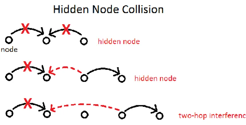
Figure 4: Illustrating some hidden node collisions. The two-hop interference range is here depicted as an extended hidden node problem. ... 9
Figure 5: Optimum packet-spacing technique in single channel single radio network. ... 10
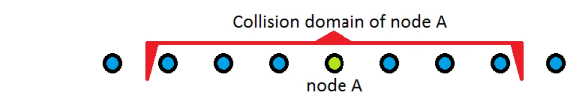
Figure 6: Illustrates the collision domain of a given node, which is the neighborhood of interest to node A. ... 11
Figure 7: The thickness of the lines indicate achieved throughput. Figure 7A shows that nodes do not have equally well access to the medium. Figure 7B shows inter-node fairness where all nodes are equally able to transmit packets. ... 12
Figure 8: Illustrates the position of the Special Header in the Body of the frame. ... 24
Figure 9: Illustrates the chain of nodes topology used ... 28
Figure 10: Throughput results of CSMA/CA. Each point is the average transmission throughput of the whole simulation duration. ... 29
Figure 11: The resulting dropped packets by buffer overflow. ... 30
Figure 12: Throughput results of CSMA/INF. Each point is the average transmission throughput of the whole simulation duration. ... 30
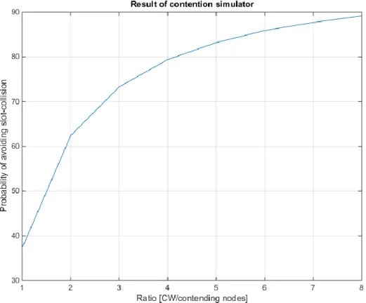
Figure 13: The output of the contention simulator (Probability in %) ... 35
Figure 14: A top-down view of the simulator structure in UML. ... 37
VIII
Definitions, acronyms and abbreviations
Acknowledgement Frame (ACK)
A response frame to indicate to the transmitter that the data frame that was just send was successfully received.
Arbitration Interframe Spacing (AIFS)
This Interframe spacing (IFS) is only used by QoS enabled nodes. AIFS is variable in length and is used instead of a DIFS in QoS aware nodes.
Collision domain The collection of all nodes with which a node can have a collision with, is referred to as the collision domain.
Contention window (CW)
The contention window is used in contention-based algorithms. When these algorithms are forced to back off, they do so with a random number chosen between “0” and CW.
Congestion Congestions occur at bottlenecks where traffic is halted or reduced due to bad network conditions.
Carrier Sensing Multiple Access with Collision Avoidance (CSMA/CA)
Is a contention-based medium access control algorithm. CSMA does not implement priority differentiation and therefore cannot provide QoS.
Destination The destination-node for a given stream or packet.
Distributed
Coordination Function (DCF)
Distributed Coordination Function is the mandatory access control layers in the MAC sublayer.
Distributed Interframe Spacing (DIFS)
This spacing is used to separate different transmissions. DIFS is equal to 28us in IEEE 802.11s. (also read SIFS)
End-to-end delay The delay between two communicating nodes on either end of a chain topology. It denotes the delay between the source of the communication and its destination.
Enhanced Distributed Channel Access with Collision Avoidance (EDCA/CA)
EDCA is directly derived from the CSMA. Its primary difference with CSMA is that it includes differentiation between packet priorities in order to establish QoS within a network.
Fairness A measurable quality of the network. It is a concept that deals with a regulatory ability of nodes to access the medium on equal footing. Fairness is further divided into Inter-node fairness and per-flow fairness.
Inter-node delay Denotes the transmission delay through an intermediate node in the mesh network. If a frame needs forwarding, then the delay it experiences through an intermediate node is the inter-node delay. (See also end-to-end delay)
IX
Inter-node fairness A measure for the equal ability of two or more nodes to access the medium.
Interframe Spacing (IFS)
The various different spacing or idle periods that must occur between different frame transmissions.
Jitter The measure of delay variation. There are different ways to calculate jitter. We use one standard deviation.
Link-layer The second layer of the OSI-model. This layer has two sub-layers called the Link-Layer-Control (LLC) and Medium Access Link-Layer-Control (MAC).
Medium Access Control (MAC)
One of the sub-layers of the link-layer. This layer is responsible for coordinating the access to the medium. This layer is further divided inti sub-layers of its own. Among others are the Distributed Coordination Function (DCF) and the Point Coordination Function (PCF) for medium access control.
Mesh Points (MP) Nodes with mesh capability. Also called Mesh Station (MSTA).
Network allocation vector (NAV)
The NAV is a timer in the MAC-layer that is set with the content of the duration field of every header received. A higher than 0 value in NAV indicates that a transmission is ongoing. It is used to prevent collision. This is a type of virtual carrier sensing (V-CS).
Per-flow fairness Per-flow fairness is a measure for the equal ability for streams of equal priority to flow with equal throughput.
Physical carrier sensing (P-CS)
The regular carrier sensing performed by the physical layer.
Physical layer The first layer of the OSI-model. This layer handles all physical transmission and carrier sensing (P-CS) of the medium.
Point Coordination Function (PCF)
Point Coordination Function is a general classification of all centrally coordinated medium access control and is only used by access points. The access point has the role of the Point Coordinator (PC).
Quality of Service (QoS) Certain uses of the network, like the communication of Real-time applications, need a minimum network quality as measured by its end-to-end delay, jitter and minimum
throughput in order to function properly. QoS usually denotes those establishments that allow such high demanding cervices to function properly. The EDCA/CA algorithm allows for QoS.
Random number (RN) A random number between 0 and CW to be used for contention.
RTA (Rapid Trafic Adaptation)
A network quality that denotes a network’s ability to quickly change to changing trafic communication patterns.
X
Request To Send and Clear To Send (RTS/CTS)
RTS and CTS are two different packets that are used to announce an immediate transmission to all nearby nodes.
Short Interframe Spacing (SIFS)
A frame spacing used only before a frame that is an immediate response to the previous frame, like the ACK. It is also used in burst transmissions to separate the packets from each other when multiple data packets are sent continuously after each other. SIFS is equal to 10us in 802.11s.
Sink A node that serves as the destination of a stream of packets.
Slot-collision (SC) A type of collision that cannot be detected, and this is when two nodes pick by chance the same random number to contend.
Source The source of a stream or packet in the network.
Special Header (SH) A new header specially devised in the proposed algorithm.
Unicast A transmission intended for a specific receiver. An acknowledgement is required for the reception of this type of transmission.
Virtual carrier sensing (V-CS)
A method for preventing transmission when there is ongoing transmission. This form of carrier sensing is performed by the MAC-layer.
1
1 Introduction
1.1 Background
TerraNet AB is a Swedish company that intends to use mesh-networking technology, using ordinary Smartphones and Wi-Fi communication between them, to provide Internet and telephone connectivity in rural and poor areas around the world where there is no advanced communication infrastructure. Mesh networking is assumed to be a cost-effective way to solve the last mile problem.
In a mesh network, nodes can independently connect themselves with all or many neighboring nodes. The result is that there is no centralized control for how the packets are routed. This stands in contrast to the widely used star topology that we use in our homes. In a star topology, the Wi-Fi-router creates the connections, and nodes must be associated with it in order to enter the network it creates. Individual nodes, called stations, cannot create their own network.
1.2 Area of work
The main area of our work lies in the multi-hop feature of the IEEE 802.11s standard, [1]. This standard is one of the latest additions to the Wi-Fi standards, and enables Wi-Fi nodes to communicate in a mesh topology by allowing all nodes in the mesh network to act as intermediate routers for each other’s traffic. Mesh nodes use the multi-hop feature to keep their connections over a greater range than their own transmission range.
The standard is based on the 802.3 stack (Ethernet), but it has replaced the Physical (PHY)-layer and the Medium Access Control (MAC)-layer with those in 802.11 (Wi-Fi). Furthermore, it adds additional functionality to the MAC-layer, which effectively turns the entire implementation to a mesh-enabled stack. [1]
Figure 1 shows the common single-hop approach that is currently widely used in homes and offices. Here the MAC layer does not route any packets, as there is only one hop to take care of for the MAC.
Figure 1: A single hop wireless network, STA can be a PC, TV or a smartphone. (Picture is modified. Original source: http://sysmagazine.com/posts/199508/)
The way the new mesh is working is to let the higher-layer protocols ‘think’ that they are operating in a LAN with just a single hop to the closest access point (gateway to other networks, like Internet). The MAC-layer creates the abstraction against all the complexities of the mesh topology. Generally, the MAC-layer handles all routing within the mesh that is made up of Mesh Points (MP). This is depicted in Figure 2.
2
Figure 2: The thick blue line shows an example path through the mesh. The complexity of the local mesh network is abstracted by the MAC-layer. Higher layer routing protocols take over when the packet arrives at the portal. The red line circle all mesh points that make up the mesh-network.
(Picture is modified. Original source: http://sysmagazine.com/posts/199508/)
For this reason, the area of attention for many mesh researchers is confined within the Medium Access Control (MAC) of the stack. This layer contains routing protocols, like the Hybrid Wireless Mesh Protocol (HWMP), to handle all routing within the mesh. It further contains the medium access control algorithm from which it has earned its name and uses it to time its access to the medium. The mandatory medium access control algorithm used by the standard is called CSMA/CA and is explained in detail in Section 2.3. The MAC-layer is the area of our research and our focus is on the added multi-hop feature and its implications.
1.3 Why mesh networking?
The future of communication comes with a great sense of freedom empowered by the newly standardized mesh networking. The greatest advantage with mesh networking is that it is easy to set up since it is self-forming. No configuration is required. The embedded software inside each node will take care of forming and configuring the network with each node that is added to it. Because of this, it is also self-healing with the ability to recover from broken connections due to dead nodes. Mesh networking offers multiple paths for packets to traverse, and this makes connections resilient. Because the network is independent of infrastructure and has no hierarchy, it is also scalable and can grow as more nodes come in range of one another. Nodes can be deployed, upgraded, replaced or removed regardless of their role in the network. On top of all this, it is wireless. Wireless network can go where wires cannot and this gives huge flexibility to companies and private homes and the implementation of Internet of Things (IoT).
Unfortunately, there are shortcomings as well. Too many hops result in high network latency, and real-time applications like voice and video can be negatively affected by this. Mesh networking is also vulnerable to high node density (small areas with many communicating nodes). It worsens their access to the medium due to high contention levels. This leads to more collisions and will reduce throughput in the network.
3
1.4 Problem description
TerraNet is studying the low throughput problem of the MAC layer in the case of mesh networking according to IEEE 802.11s. The problem is the exponential degradation of end-to-end throughput as a function of number of hops in a chain of nodes that operates according to the IEEE 802.11s mesh standard. The underlying factor for throughput degradation should be understood and a method should be developed that can reduce the problem.
1.5 Limitations
The authors of [2] indicate that packets are dropped almost only due to buffer overflow and the authors of [3] see packet drops due to the retransmission limit to be a major contributor to throughput degradation. Retransmissions further reduces throughput by creating delays in the transmission. These are all cited factors for throughput degradation.
We consider these as sub-problems to the throughput degradation problem described above. We choose to concentrate on the issue of packet drops due to buffer overflows that indicates uneven transmission rates between nodes. Our area of research will focus on intra-mesh medium access control.
We will not consider …
Routing. We will assume that routes are already in place. Mobility. We assume stationary nodes.
Node discovery and peering Security
Transmission power. All nodes will be set to transmit with the same strength.
We will focus on the chain of nodes topology, which is important research for Internet backbones consisting of only Wi-Fi transceivers, where the problem of throughput degradation is often observed. Our work is only constrained within the mesh, which only consists of mesh-points. For example, we will
not consider the interaction of mesh nodes with access points.
1.6 Research question
The goal of this thesis work is to reduce the throughput degradation. In literature, there are described a number of solutions trying to alleviate the problem of throughput degradation in mesh networks. The most common solution is CSMA/CA. However, most solutions are not without their own shortcomings and therefore not suitable for use in TerraNet’s network of mobile phones.
Research questions addressed in this thesis are:
1. How is CSMA/CA causing buffer overflow in nodes?
2. Can implementing fairness in CSMA/CA reduce throughput degradation?
1.7 Hypothesis
We state the following hypothesis for our research:
Reduced channel capacity is a consequence of the shared medium in multi-hop networks.
4
The collision avoidance mechanism of CSMA/CA causes unfairness and starvation in multi-hop wireless networks.
1.8 Requirements and assumptions
This work aims at being used for, but not limited to, voice and video communication on phones. We will for this reason focus on the restrictions and capabilities of a regular Wi-Fi-module on board a smartphone. We will only use one single transceiver on each node.
Our work will be based on the assumption that the Wi-Fi-modules:
… can only listen while it does not transmit (half-duplex) … have only one transceiver per node
… operate on a single channel
Furthermore, we assume in the following that the interference range is twice that of transmission range, and that carrier sensing range is almost between one and two transmission ranges.
1.9 Outline of report
Chapter 2 describes wireless communication in general and specific details of the new 802.11s standard. This chapter starts very basic, explains the purpose of the MAC-layer, and explains its position in the OSI model. The algorithm of medium access control is also introduced.
Chapter 3 contains descriptions of related works. We go through some of those that we have more frequently referenced, and those we wish to comment in the discussion. This chapter gives insight into the field of multi-hop networking and further open the subject of the MAC-layer.
Chapter 4 describes our way of approaching the main problem and the methods used.
Chapter 5 contains our own analysis and is the basis of our proposal for how end-to-end throughput can be enhanced.
Chapter 6 describes our proposed algorithm.
Chapter 7 presents the results of simulation obtained for both pure CSMA/CA and the proposed algorithm.
5
2 Theoretical background
This chapter is divided in four sections. The first section describes the OSI model and visualizes transmissions and the transmission process for the reader to give better abstraction for what lies ahead in the coming chapters. The second section deals with introducing known problems of wireless communication. It is meant to open the problem domain for the reader and has medium level difficulty. The third section details the contention-based algorithms that are widely used in wireless communication. Most of our research deals with the concepts of these algorithms.
2.1 Overview and structure
2.1.1 The different layers of The Open System Interconnection model (OSI model)
In a network, nodes are the units that communicate with each other. Their firmware implementation is by the Open System Interconnection (OSI) model described in layers. This layering is meant to divide the big problem of communication into smaller sub problems. These layers prepare a packet in different ways in order to prepare it for transmission. [4]
The layer of interest for our work is mainly the MAC-sublayer, but we will also briefly introduce the transport and Network-layer here too.
Transport layer (layer 4)
The transport-layer provides high-level services to higher layers of the OSI. This layer is concerned with the end-to-end aspect of communication and can deliver reliable or best effort communication between two end nodes.
Network layer (layer 3)
The network layer is able to create a route and navigate a packet through the network too its designated destination.
Link layer (layer 2)
The Link-layer considers only the communication to the next hop and handles therefore all links to its neighboring nodes. It consists of two sublayers, Link Layer Control (LLC) and Medium Access Control (MAC). MAC handles medium access timing for each transmission with the purpose of avoiding and handling collisions.
Physical layer (layer 1)
The Physical-layer is the actual hardware performing the signal transmission. The physical layer may also come with added capabilities, such as being able to sense the medium for a carrier frequency and determine whether there are ongoing transmissions. This feature is called Physical Carrier Sensing (P-CS), and is frequently used by the MAC-sublayer if available.
The description of the physical-layer is specific for the technology in use, in our case it is defined by IEEE 802.11 (Wi-Fi).
2.1.2 What is different in the mesh standard
All the changes made for enabling mesh communication is confined within the MAC-sublayer. The main addition and purpose to this layer is Multi-Hop. This feature enables nodes to communicate with a distant node over a series of hops rather than just one hop. Nodes can therefore also communicate directly to each other,
6
rather than through a center-node. This effectively creates a Mesh topology in the network where a node has many connections to its neighboring nodes. The MAC-layer must create an abstraction from the complexities of the mesh towards the higher layers. This has simplified the implementation of the mesh standard and reduced the focus on the MAC-sublayer while keeping the upper layers believing that they are part of a single-hop network. [1]
2.1.3 The MAC-sublayer
The MAC-layer itself contains the DCF-sublayer. DCF (Distributed Coordination Function) is used to coordinate the access to the medium when there are several communicating nodes trying to gain access to the medium. This function is called distributed because it can operate without the need of a centralized controlling node. The DCF operates using a medium access control algorithm, like the CSMA/CA. This algorithm is described in Section 2.2 and CSMA/CA is the focus of this thesis.
2.1.4 MAC responsibility and limitations
MAC (Medium Access Control) is responsible for the timings with which a node will try accessing the medium for transmitting a frame. The main responsibility of MAC is medium access control and hence the avoidance of concurrent transmission that could result in collisions. In case of a collision, it is highly likely that the receiver of one or both frames is unable to decode the signal into usable data and the time spent transmitting those frames is considered wasted. If the frame can be decoded and understood, the receiver must respond with an acknowledgement-frame (ACK-frame) to the transmitter. [1]
Nodes can only afford to try transmitting the same packet a limited number of times before they must drop it (delete it without successfully transmitting it). Furthermore, each node has a limited memory and can only store a limited number of frames. For this reason, it is best if they can keep their buffers empty by forwarding their received frames as soon as they can.
2.1.5 The make-up of a MAC-frame
A frame consists of two parts, the header and the body of the frame. The body can further be divided in the payload (carries useful data) and the FCS (frame check sequence), which enables the receiver to determine whether the packet was successfully decoded from the medium. If the FCS matches, the receiver will transmit an ACK-frame and indicate a successful transmission.
The header contains important information for all nodes to receive, while the body is only intended for the actual receiver of the frame. The header has a RA-field (Receiver Address) that indicates the intended receiver, and a duration field that indicates how long the transmission duration will be until the end of the following ACK-frame.
2.1.6 Visualizing transmission
Nodes communicate using a defined standard so that the activities of all nodes are predictable. For the MAC-layer, it is vital to keep certain time limits and timeouts between transmissions. The most important ones are the Inter-frame spacings (IFS): Distributed Interframe Spacing (DIFS) and Short Interframe Spacing (SIFS). DIFS is used between two frames that are unrelated while SIFS is used before a frame that is an immediate response to the frame before it. Figure 3 below illustrates an optimal performance of the MAC-layer during transmission of data between two nodes. The data frames are transmitted by node A and are acknowledged by ACK-frames from the receiving node (node B). These frames are exactly a SIFS apart. DIFS is always used before a DATA-frame.
7
Figure 3: Visualizes transmission and the position of SIFS and DIFS. The duration of the InterFrame Spacings are constant (SIFS = 10us, DIFS = 28us)
2.1.7 Throughput vs. Link-speed
To understand channel capacity, it is important to understand the difference between the link speed and throughput. The link-speed is the rate with which the physical layer modulates bits into symbols. The throughput is the number of transmitted data-bytes (bits)/second.
2.2 Introduction to contention-based algorithm
In the following, we will explain in detail the inner workings of the CSMA/CA algorithm and briefly mention how DCF-sublayer uses CSMA/CA for medium access control.
2.2.1
Distributed medium access control
When discussing medium access control, it is common to talk about the Distributed Coordination Function (DCF)-sublayer that is making use of the Carrier Sense Multiple Access with Collision Avoidance (CSMA/CA) algorithm to coordinate access to the medium. CSMA/CA is a distributed control mechanism, which implies that it is able to coordinate the access to the medium without the nodes exchanging information with each other. This is useful considering that networks first need to initialize and startup before they can interact at a higher level with more sophisticated algorithms. It is therefore the fundamental access scheme and mandatory to implement in all Wi-Fi standards (including IEEE 802.11s [1]).
CSMA alone can only try to avoid a collision but cannot handle any incurred collision. Therefore, there are different extensions for this algorithm. For wireless communication, the Collision Avoidance (CA) extension is used and it is able to reduce the probability collision in the medium. CSMA/CA can be explained in two parts. The first is contention and the second is Collision Avoidance (CA).
An important concept in the CSMA algorithm is division of time in time-slots and each time-slot has a duration, which is called an aSlotTime.
2.2.2 Contention
In case the transmit buffer of the MAC-layer is empty and a new packet arrives in the MAC to be transmitted, the algorithm allows for the immediate transmission of that packet after a DIFS period. This is the normal case. In the case that the DIFS period is interrupted by a transmission, the node must start the backoff procedure. The backoff procedure of the CSMA algorithm in the nodes that are competing to access the medium use a randomly generated number, RN, between 0 and the Contention Window (CW). A CW consists of a number of time-slots between aCWmin = 15 and aCWmax = 1023. Contention works by waiting a number of time-slots indicated by the random number before starting the transmission. The contending node must carrier sense the medium during each aSlotTime and if the medium was idle, the node must decrement its RN-value by 1 until it has reached 0. When it reaches 0, the node can transmit 1 frame. When the node senses the medium to be busy,
8
(ongoing transmission detected), it may not decrement its RN-value before the medium again has been found idle for a whole DIFS duration.
In case, there are no pending packets to be transmitted after the last transmission, DCF will start a new contention, but without transmitting when complete. This is done only to make sure that all transmissions are separated by a contention period. Additionally, DCF is designed to transmit one packet after the other as fast as possible.
2.2.3 Collision Avoidance (CA)
Contending for medium access may not always be successful. There are situations in which a contention ends in collision. Collisions are detected by a node when the expected response in the form of ACK was not received during the ACK timeout. According to the rules of collision avoidance, the CW must be doubled (expanded) and a new random number must be generated between 0 and the new CW. After any successful transmission, the CW is reduced to its minimum value as defined by aCWmin.
The backoff procedure is called the binary exponential backoff, because for every failed transmission nodes double their CWs (until it reaches aCWmax = 1023) and contend again. By having a large number like 1023, the probability of two nodes choosing the same number by random is reduced to 1/CW, where CW is the largest CW among the contending nodes after the expansion. This gives a good chance that the next contention will succeed.
2.3 Problems of Wireless Communication
The general problems of wireless transmission described here are a great part of what the MAC-layer must accomplish using its medium access algorithm. For this reason the notion of collision and hidden nodes are difficult to avoid even when considering other problems of the MAC-layer, as all changes must make sure not to neglect the collision avoidance property of the MAC when making improvements on its other properties. The next subsections will shortly describe hidden nodes and collisions and define the collision domain that is a useful concept of what can be considered as the neighborhood of a node. We then move on to describing the notion of fairness among contending nodes.
2.3.1 Shared medium
The medium is what the transmissions are going through. In the case of 802.11 (Wi-Fi), the medium is the air and is called the Wireless Medium (WM) and is shared by all communicating nodes. Medium can become saturated which means that the medium is constantly and without interruption used for transmission.
Interference
One of the greatest problems faced due to shared medium is interference among concurrent transmissions. One node’s transmission can interfere with the transmission of others. This implies that nodes must take care in not transmitting at the same time, which imposes each node to know when other nodes have the intention to transmit. Failure to do so will effectively mean reduced network performance measured in throughput, delay and jitter. In order to avoid concurrent transmission and thereby collisions, nodes are capable to sense the medium before accessing it.
The different types of collision
All concurrent transmission that results in interference is defined as a collision. An example of slot-collisions, see Figure 4, can occur when two nodes within carrier-sensing range, start transmitting to a same node at the same time. If two nodes are unable to carrier sense each other, they are hidden from one another and can
9
therefore start transmitting at any time. This is due to the limited range of carrier sensing. This range is shorter than two transmission ranges and lead therefore to hidden node.
In addition, there is the two-hop interference problem. Nodes often interfere with each other over a distance of two-hops. This means that if the transmission range is 200 meters and the nodes are placed with this distance apart in a chain topology, then nodes 400 meters apart are able to interfere with each other’s reception if when one node is transmitting while the other node is trying to receive a frame. The last example in Figure 4 shows how two transmissions are done by node A and B and that one was unsuccessful due to the interference that it got from the other node’s transmission over two-hop distance. The two-hop interference range effectively extends the hidden node problem and adds more hidden nodes to the collision domain as formally defined in section 2.3.3. Figure 4 further shows other examples of hidden node collisions.
Figure 4: Illustrating some hidden node collisions. The two-hop interference range is here depicted as an extended hidden node problem.
2.3.2 Reduced channel capacity
The reduced channel capacity is analyzed in [5] [2] [6] and it is caused by the fact that the Wireless Medium (WM) must be accessed repeatedly by different nodes for the transmission of the same packet so that it can be forwarded along a chain of nodes. Whereas it was only necessary in the single-hop counterpart to transmit a packet once, and then the packet would be forwarded by the AP using wired medium. This resulted in less medium utilization so that the medium could be used for further packet transmissions from the same wireless node. This yielded a higher efficiency over the multi-hop scenario, since multiple transmissions of the same packet does not count as more than one packet in throughput calculations. Channel capacity is therefore always measured relative to that which is achievable in a single-hop communication between two neighboring nodes for comparison.
It is possible to illustrate the reduction of capacity in a multi-hop network by considering a chain topology like the one depicted in Figure 5. The nodes are numbered from 1 to 10. None of them necessarily has to be considered as the source or the destination. It can just be seen as a segment of a much larger chain. The diagonal lines are transmissions and they are going from left to right. Time is progressing downwards.
10
Figure 5: Optimum packet-spacing technique in single channel single radio network.
The behavior seen in Figure 5 is the optimal transmission rate for two-hop interference range. It is evident that rapid successive transmissions from the same node is not advised due to the transmission of neighboring nodes that could results in interference if packets were send too fast after each other. In fact, this is the fastest rate at which nodes should be transmitting along a chain of nodes. This rate is called the network capacity or channel capacity. There is total inter-node fairness in the way transmissions are done in Figure 5 and therefore none of the nodes needs to buffer any packets. Delay and jitter are also the lowest possible. [2] [6]
If we consider an error-free environment, the maximum sustainable throughput will in this case be ¼ of the throughput in a single-hop communication and constitutes the best-case scenario in [2]. The illustration can also be called packet spacing. The aim with packet spacing is to keep the packets far from each other so that they cannot collide by keeping them out of each other’s collision domain, which is defined below. Just like in Figure 5. One implementation of this approach is done in the TCP protocol and manages the sliding window size to an optimum size called W*, as described in Section 3.3. This optimum value effectively restrict the amount of packets in transit between the two end-nodes [7].
The throughput of ¼ is thus called the network capacity. This is the highest sustainable throughput along a chain of nodes topology with two-hop interference range. Higher than this throughput will result in unfair access relative to neighboring nodes that are because of this, no longer able to forward their packets equally fast as they receive them, resulting in dropped packets. [2] [8] [9]. Unfairness will be further detailed in section 2.3.4.
2.3.3 The collision domain
The definition of the collision domain is important for understanding our choices made for the proposed algorithm, which is the main result of this paper. This section clarifies how a number of neighboring nodes can affect the performance of a single node.
11
We learn about collision ranges and interference in section 2.3.1, and in section 2.3.2 we learned about what is causing its reduction in multi-hop. Using our understanding from both sections, we can derive a collision domain. The identification of the collision domain is a simple way of denoting the nearby neighborhood of a node that can affect a given center node from its point of view.
Let us consider the following statement: (considering two-hop interference range)
A node may not transmit if any of its neighboring nodes within two hops are about to receive a frame, in order not to interfere with its reception.
This would eliminate all collisions among nodes, however it is difficult for neighboring nodes to know when a particular node is about to receive a frame, just as well as the node itself may not be aware of that.
The next statement is equivalent to the previous:
A node may not transmit if a neighboring node within three hops is about to transmit a frame.
This too would eliminate all collisions among nodes. Why the third-hop node also needs to be considered, is because that it could be transmitting to the second-hop node. The reception of the second-hop node can be interfered by two-hop interference range. This last statement is somewhat easier to work with, since the transmitter will be able to know when it has a packet for transmission.
Using this last statement, we can devise the following collision domain as pictured in Figure 6.
Figure 6: Illustrates the collision domain of a given node, which is the neighborhood of interest to node A.
This identified collision domain will be referred to from now on. The medium access made by node A will interfere with the transmission of 6 nodes that are within its collision domain. Seen the other way around, the activity of these 6 nodes will influence the decision-makings of node A. Therefore, the nodes within a collision domain are mutually dependent. Any decision-making of a node must therefore consider the actions of other nodes within the collision domain.
From the definition of the collision domain, we can now see why the channel capacity is reduced in a shared medium with multi-hop enabled communication. As described in the previous section, nodes must wait until the packet they just transmitted has been forwarded out of their collision domain. Also therefore, a distance of minimum three hops must be accomplished by any packet spacing approach.
2.3.4 Fairness
Fairness is a property of the network. Fairness becomes only an issue when the medium nears saturation level. Saturation means that the medium is being constantly used without interruption.
The concept of fairness deals with regulating the average access of nodes to the medium. Since the multi-hop network is a chained network of mesh-enabled nodes that both generate own traffic and forward the traffic of other nodes, it is possible that nodes that lie far from their end-destination are starved and achieve little
12
throughput [8]. This happens naturally without nodes actively putting the transmission of their own data-packets before others. There are many reasons for why unfairness can emerge, but they all fall in two categories, inter-node fairness and per-flow fairness. Inter-inter-node fairness deals with enabling all inter-nodes to gain equal share of the medium, while per-flow fairness deals with fairness among different streams of data. With inter-node fairness, no node is starved from accessing the medium and all nodes access the medium on equal footage. With per-flow fairness, no stream is starved regardless of their distance in hops to their end-destination.
Inter-node fairness
Figure 7 shows the transmission of node 1 to node 3 through node 2, and shows even the relative throughput that the nodes achieve with the colored lines. Thicker lines denote higher throughput. The medium access rate between nodes 1 and 2 are uneven and node 1 is getting the most through. The ideal throughput achievable by inter-node fairness would have looked like Figure 7B. Here, nodes 1 and 2 are transmitting with equal throughput.
Figure 7: The thickness of the lines indicate achieved throughput. Figure 7A shows that nodes do not have equally well access to the medium. Figure 7B shows inter-node fairness where all nodes are equally able to transmit packets.
The medium is saturated in both Figure 7A and Figure 7B. In Figure 7A, node 2 is partially starved and unable to forward all the packets that it received from node 1. As a result, node 2 is likely to fill its buffer and start to drop packets when its buffer is overflowing. Figure 7B shows what implementing fairness could mean for node 1 and 2. They have been able to equalize their medium access rates so that node 2 received just as much as it can transmit. As a result, node 2 will not drop packets due to buffer overflow. Since there is only one stream involved, there is no need for per-flow fairness and Figure 7B is showing the best result achievable.
The greedy sender
The term “greedy sender” describes a node that continuously contents for the medium and makes a transmission regardless of the level of contention in the medium, and is mentioned in [2] [10]. An example of such a node is node 1 in Figure 7A.
The greedy sender is a consequence of using the IEEE 802.11 MAC (DCF with CSMA/CA) in a multi-hop network with shared medium. As stated in section 2.2.2, nodes using this algorithm transmit as fast as they can and thereby saturate the medium and starve other nodes from accessing the medium with an adequate rate.
13
Nodes are generally unaware about the buffer state of each other. Therefore, the existence of the greedy sender causes frequent buffer overflows when nodes are unable to forward their previously received frames in order to free up more buffer space before they receive the next frame.
14
3 Related work
3.1 An Analysis of Hidden Node Problem in IEEE 802.11 Multihop Networks (2010) [3]
This paper considers the performance degradation of Multihop networks of IEEE 802.11 due to hidden nodes. By using a simple model, they present an analytical analysis for the problem with which they could use to optimize the conditions.
This paper concludes that the hidden nodes have a greatly negative impact on the overall network performance and cause packets to be dropped. They base this on simulations showing that by increasing the offered
throughput, they can see a steady rise in throughput that is proportional to the offered throughput, only to abruptly decrease passed a certain throughput threshold.
They build their analysis around three assumption in order to make it simple. They assume no retransmission, neglect the ACK timeout and assume that all nodes in the network has the same CW. Evidently, they conclude that if considering that the frame duration is fixed, then the probability of hidden node collision is reduced for larger random numbers which also implied larger and equal CW-values among nodes. The result of this paper further prove that smaller frame durations have greater probability of transmission success in the presence of hidden node. Long frame durations have limited or no chance of transmission success in the presence of hidden nodes.
This work is relevant for our study of the problems, because it deals with the CW and apparently has found a condition in with the hidden node is more like to be avoided using the CW-value. The conclusion was the equal CW-value among nearby nodes. They prove the accuracy of their model by showing that it is well matched the simulation results they get using NS2. Their simulations shows a rise in throughput forever increasing the aCWmin from 32 to 256. However, the advances seem to wear off, as aCWmin get higher. They argue that the larger aCWmin causes longer overhead, which affects the throughput.
3.2 iQueue-MAC: A Traffic Adaptive duty-cycled MAC Protocol with Dynamic Slot
Allocation (2013) [11]
This work raises the problem of throughput and delay in a Wireless Sensor Network (WSN). Although their work may not be within our field, it still adds viable information and insight in methods and results they produced.
This is a follow up paper on the authors’ two previous work, which resulted in two algorithms, all which had strengths and shortcomings. The aim is to enhance throughput and especially for burst transmission in a manner that is rapidly adaptive to traffic load. This allows for reduced power consumption and transmission delays. Their setup uses two distinct type of nodes, one router and many end-nodes. The end-nodes collect data and transmit to the router. Their algorithm is called iQueue-MAC and is a hybrid between regular CSMA/CA and TDMA (Time Division Multiple Access). This combination allows using the flexible CSMA algorithm in light load condition while TDMA is used at high load conditions and conditions that create burst traffic. With this method, the authors could overcome the inherent drawback of the contention-based algorithm. The mechanism for switching between CSMA and TDMA requires that the nodes inform the router about how many packet they currently have queued. This is done by piggybacking this one-byte information in start of the body section of every MAC-frame. Their arrangement does not violate the standard, according to the authors. They also show that can work in real implementation.
15
Their algorithm uses a superframe that is repeated in cycles. The superframe is just a period that contains other sub-periods. The following is the sequence of action during the superframe. First, the nodes wake up and start contending using CSMA in the Contention Period. They may only transmit one packet and piggyback their buffer-lengths in that packet. Secondly, at the end of the Contention Period the router will use the received information to generate a TDMA-scheme. This scheme is then inserted in the beacon that it transmits in the beacon period. The nodes receive this and know when to start transmitting without the use of contention. Their method has proved to be very efficient. While greatly enhancing throughput and reducing delay and reducing any buffering in the nodes, they managed to reduce power consumption equally well. Their rapid traffic adaptation method proved to have removed the bottleneck that usually arises when a sudden events creates a flood of packets in the network.
3.3 The Impact of Multihop Wireless Channel on TCP Throughput and Loss (2003) [7]
The authors of this paper have analyzed the network capacity and concluded that when considering one-hop interference range, the network capacity is 1/3 of what can be achieved with one-hop communication between two nodes. In case of two-hop interference range, the network capacity was found to be at most 1/4.
Their theory is to avoid a higher offered throughput from the node than network capacity. In order to combat the throughput degradation problem caused by offering higher throughput than the network capacity, they modify the sliding window mechanism of TCP and regulate the sliding window size to an optimum value called, W*. This size is regulated using the received ACKs as feedback, and it eventually means that the amount of packets in transition between source and destination is limited so that there is one packet in any given collision domain across the chain topology. This method is equivalent to packet spacing in which the packets are deliberately delayed at the source until the latest transmitted frame has been forwarded out of the collision domain.
This work shows that keeping the throughput below network capacity will in fact remove throughput degradation. The authors also correctly detected that certain topologies are in favor while others do not work. This work is relevant for us, because it displays what should be accomplished in order to combat throughput degradation and confirms the channel capacity in two-hop interference range.
3.4 Achieving Collision Avoidance and Fairness in CSMA-based Wireless Mesh
Networks (2011) [12]
The method provided here uses the duration/ID field of the header to inform other nodes about the duration of a future transmission rather than the duration of the current transmission to the end of the following ACK
transmission. The author’s work is tailored for one-hop interference range only.
This method is called Grant-To-Send (GTS). This should be called grant-to-forward as it creates a transmission duration envelope. Using this protocol, a node can contend using CSMA/CA, win the medium, and transmit a packet. When transmitting it must indicate the length of the transmission to be twice as needed in the duration field (all nodes have the same link-speed). All nearby nodes that overhear this header will then be restricted from accessing the medium for this prolonged duration. When a receiver of a frame receives the frame after just half of the stated duration in the header, it will immediately forward the frame without contention. Collisions are avoided because the two last nodes (including the immediate transmitter) are restricted from accessing the medium since a whole frame duration is remaining. This is made possible by virtual carrier sensing that uses the duration/ID field of the header.
16
The author of this paper only work with a single stream in a single direction along a chain of nodes topology. Using a heuristic calculation, he is able to predict the correct duration time that needed to be placed in the header. His function is able to provide the correct duration 98% of the time. The implication of not stating the correct needed duration for own transmission and the next transmission has two sides. On one hand, a too long duration will reduce efficiency and effectively reduce channel capacity. On the other hand, the next node will not be able to transmit the frame in the remaining time and will defer the transmission and waste the time that was given, also reducing efficiency. As a result, the end-to-end throughput was enhanced to closely match channel capacity. The author of this paper introduces this method for both Wireless Mesh Networks (WMN) and Wireless Sensor Networks (WSN).
This work has relevance since it is a measure to effectively avoid too frequent transmission from the same node and allow the already transmitted frame to be forwarded out of the collision domain before the next frame is transmitted. This work effectively reduced throughput degradation in a chain topology.
3.5 EDCA Based Congestion Control for WLAN Mesh Networks (2006) [13]
In this paper, the method of congestion control is to tweak the QoS (Quality of Service) parameters of the EDCA (Enhanced Distributed Channel Access) in order to control throughput. This method controls throughput by changing the AIFSN (Arbitration InterFrame Spacing Number). The proposed algorithm must actively measure the throughput of all flows out of the node (downstream) and use unicast transmission to deliver periodic measurements of the throughput so that the sending nodes (upstream) can reduce their transmission rate to this node.
The authors of this work only consider a chain of nodes topology and transmit only one stream along the chain in one direction. Their work effectively removed all packet drops due to buffer overflow and their measurements got close to the channel capacity, since the reported throughput measurements were all made for successful transmissions. This reduced the upstream throughput when collisions reduced the downstream throughput, effectively reducing throughput below channel capacity.
This work has relevance for us because it demonstrates how a mechanism without knowledge of channel capacity can be able to regulate throughput to the sustainable throughput across a chain of nodes topology.
3.6 Improving Throughput and Fairness in Multi-hop Wireless Mesh Networks Using
Adaptive Contention Window Algorithm (ACWA) (2011) [8]
The authors of this paper want to enhance throughput of nodes that are multiple hops from the gateway relative to the throughput of those close to the gateway. The authors see this as a fairness issue between nodes close and far from the gateway, which results in starvation for those far from a gateway. Based on their mathematical analysis they conclude that the probability of a packet arriving successfully at the gateway varies inversely with the number of hops. In order to improve this, they implement an Adaptive Contention Window Algorithm (ACWA) that controls the CW in pursuit of gaining different medium access rates. By giving higher medium access rate to nodes further away from the gateway, those nodes will be able to deliver an equal amount of packets to the gateway as those close to the gateway. They also look at how many hidden nodes a node has when adapting its CW. The main idea is to compensate the loss of packets along the chain with more packet
transmissions for nodes that are further away from the gateway.
Their approach is simplified by dividing the nodes in two groups. The first group consists of all nodes that are only one hop from the gateway, and the second group is all the remaining nodes.
17
Their implementation uses complex mathematical computations that require the use of external software like Maple to compute the CWs. The authors realize that the computations are not feasible to implement in a resource-limited node and wish to address this in a future work. Their implementation solves the problem and equalizes throughput.
Their work is relevant to us because it proved that CW could be used to control throughput.
3.7 Capacity of Ad Hoc Wireless Networks (2001) [2]
The authors of this work analyze the channel capacity of the mesh protocol relative to the throughput achieved over a single hop communication. The purpose is to determine if multi-hop networks are scalable or only applicable for small networks. This is because they see channel capacity as an increasingly limiting factor for larger networks, because communication paths will get longer too and use many network resources along its path.
They start by analyzing a chain of nodes topology and later move on to a lattice with first horizontal and then both horizontal and vertical traffic to see how the 802.11 MAC (CSMA/CA) is able to handle this. They predict different channel capacities for each topology and later test them to see if 802.11 MAC can achieve them. They predict a channel capacity of 1/3 when considering one-hop interference range and ¼ when considering two-hop interference range. Their testbed is however only able to achieve a throughput of 1/7 when using CSMA/CA. In order to shed light on why CSMA/CA is not able to achieve the predicted maximum channel capacity they conduct an experiment in which they simulate a chain of nodes topology using CSMA/CA and varying offered throughput. The result showed that when a higher than channel capacity is offered to the source node the end-to-end throughput would sharply decrease below channel capacity. While varying the offered throughput they could see that end-to-end throughput got at one point very close to the expected 1/4 throughput. At this measurement point, they were offering the throughput of the expected channel capacity. From this, they concluded that while the 802.11 MAC (CSMA/CA) is capable of transmitting at the optimum rate, it is incapable of discovering the optimum schedule of transmission by itself and result in packet drops due to buffer overflow (congestion loss).
The authors state that the problem arises due to variation in the surroundings of nodes. The nodes are not equally affected by the surrounding competition in the medium. Node 1 is only sensing a single node and is being affected by 3 nodes in its neighborhood, while node 3 in a chain of 7 nodes sense the transmission of 2 nodes and is affected by 5 nodes. This is because the end nodes in a chain of nodes topology have fewer neighbors than in the middle of the chain. This leads to a higher packet injection into the network by node 1 than the subsequent nodes can forward, leading to packet drops due to overflow at node 2 and 3. They authors call this unfairness because they argue that it is the first few nodes in the chain that starve the subsequent nodes and state that capacity allocation might solve this issue.
They analyze the capacity of a lattice topology (square). The analysis with only horizontal traffic had an expected capacity of 1/12 for each chain and 802.11 MAC achieved 29% less than that. The analysis of both horizontal and vertical traffic had a predicted capacity of 1/24 and it was almost achieved by the 802.11 MAC. The reason was that not much had changed in the topology from the previous horizontal analysis.
They precede with random lattice local position and traffic and conclude that 802.11 MAC is more efficient for orderly traffic. This work has identified traffic patterns that allow higher capacity than others do.
18
This work is relevant for us, because it confirms two-hop interference range and shows how it must be perceived and leads us to a correct interpretation of it. Furthermore, it provides good analysis of the chain topology and clarifies its problems by argument and prediction, which they later verify with simulation.
19
4 Research approach
This section describes how the work was done studying the subject and researching the cause for the main problem. The job started by studying the problem in detail until we had a clear understanding for the problem before we started subdividing it.
The following few section describe the steps and order of steps to gain an understanding for the problem and finding part-solutions that together could reduce the main problem of throughput degradation. This approach started naturally with self-study, and the rest followed from the knowledge that we had accumulated by studying related works and related problems. We chose the following sequence because we thereby would have used the insight generated from studying related works and save time. This way, related work inspired both the problem analysis and the solution model.
4.1 Gaining insight in the field through self-study
To gain insight and develop our vocabulary in the field we studied a relevant portion of the Wi-Fi Mesh Standard in [1]. From here, we could use keywords to search for relevant scientific papers and be able to evaluate their relevance for our end goal.
We were then able to decide for the best approach on how to gain insight into the problem and chose the approach described in the next few sections.
4.2 Identifying possible causes
We were able to find papers that had encountered the problem and to some part described it. During these studies, we gained insight in possible causes that could give rise to the problem. Through this approach we made several updates to our research question and our area of research, in a recursive way.
The different problems were effectively dividing the main problem into smaller problems. Among the sub-problems, we agreed on choosing the most prominent problem for the thesis and left the rest for future work.
4.3 Analyzing the behavior of known implementation
Having chosen a single sub-problem (unfairness) for further investigation, we had located a major contributing mechanism that most probably was causing the main problem. Using mainly probability calculations, we were able to describe its impact on the system.
4.4 Developing solutions
Analyzing the cause and further understanding it, helped us define the required behaviors (described in chapter 6) that were needed to solve the problem.
4.5 Testing solutions
After discussing different validation methods, like considering NS3, we decided for a simple MatLAB simulator implementation.
In order to use the simulator as a verification tool for the modifications, we chose to make an initial simulation using pure CSMA/CA with which we later could compare our proposed algorithm results. This method would be able to determine whether our proposed algorithm had a positive impact on what we wanted to accomplish or enhance, since it provided us with a reference point for comparison.
20
The generality of the simulator was achieved by recreating what was found in literature under the described conditions. More on this in Appendix B.
21
5 Result - Analysis of CSMA/CA
In this chapter, we present an analysis from which we can conclude how the problem of starvation and evidently unfairness can arise with the current medium access algorithm of IEEE 802.11s.
5.1 Why we chose a CSMA-based approach
We choose to analyze and improve on CSMA/CA as our end goal. In contrast to solely scheduled-based algorithms, contention-based algorithms seamlessly allow Rapid Traffic Adaptation (RTA), which by the results of [11] has unambiguously displayed as vital for improving all metrics of the network. Scheduled-based algorithm can become too rigid in their schedules and cause large delays where there are no active transmissions, and specific rules are required to overcome this problem, which makes them more complicated. Therefore, we aim at analyzing the problems of CSMA/CA and modify it to enhance its ability to keep throughput high across a chain of nodes.
5.2 Analyzing the Collision Avoidance of IEEE 802.11 MAC
As described in Section 2.2, the mechanisms of Collision Avoidance (CA) reduces CW to its minimum value (aCWmin) the moment an ACK is received, which indicates a successful transmission. The authors of [8] state that CA does not work well in Multi-hop networks but do not give answer as to why. In the following sections, we present our analysis of the CA-mechanism and propose a scenario in which the CA results in unfairness and both argue and analytically analyze the probability of its occurrence.
We start with a thought experiment. Just consider 8 continuously contending and transmitting nodes within the carrier sensing range of each other while having aCWmin = 6 (7 possible slots between 0 and 6). Due to the low value of aCWmin, collision is guaranteed, since not all 8 nodes can pick a unique random number when there is not enough numbers to pick. Yet CA returns CW to its minimum value when the node has transmitted one frame successfully. The reason is that CA act opportunistically and does not probe the network to determine whether the contention has reduced and simply assumes that it has and seeks to enhance throughput as quickly as possible by reducing CW to its minimum. For this reason, CA can be said to be collision driven, and does not reduce the probability of future collisions. In a mesh network with large number of nodes, the minimum size of CW must be adjusted so that it is more suited for the number of nodes that at any given moment are actively contending. Considering that nodes need to forward a received frame and that this would raise contention locally around a source node, makes this a particularly important tweak.
In conjunction to the above thought experiment and by using our contention simulator described in Appendix A, we find that only 37% of the nodes will in average avoid slot-collision if the number of contending nodes and the CW used are equal (CW/nodes = 1). Whereas 62% will avoid slot-collision if CW is twice the number of contending nodes (CW/nodes = 2). This is a great improvement, but the improvement rate reduces as CW is increased. For CW/nodes = 3, we get 73% successful contentions and 83% for when the ratio is 5. Of course, the nodes must be actively contending and not just being present. This shows how important the value of CW is relative to the number of nodes that are actively contending.
Thus, reducing the CW to a preset value without considering the number of actively contending nodes in the collision domain will result in preventable collisions. We can also see that raising the size of CW ever more will forgo its benefits due to the delay it produces. Thus, there must be an optimum relation between CW and actively contending nodes within the carrier sensing range for avoiding slot-collisions.