School of Innovation, Design and Engineering
Using IPS software for decision
making when developing a
collaborative work station
- A simulation-based case study in the
remanufacturing industry
Master thesis work
30 credits, Advanced level
Product and process development Production and Logistics
Johanna Axelsson
Report code:
Commissioned by: AB Volvo, Gothenburg Tutor (company): Atieh Hanna
Tutor (university): Jessica Bruch Examiner: Antti Salonen
II
ABSTRACT
European manufacturing companies are facing challenges of increasing prices of raw material, more customized products and competitiveness from industries outside Europe. Those challenges make the manufacturing require flexible production processes. The remanufacturing industry has the advantages of produce products using less raw material and to a lower cost compared with manufacturing. This makes the remanufacturing industry a way for the European companies to stay competitive. Challenges of the remanufacturing process are the operator exposure of vibrations, monotony tasks and ergonomic issues when disassembling the incoming core. To meet the challenges and stay competitive the Swedish manufacturing industries is currently examine the advantages of collaborative robots and how implementation of collaborative robots can improve production. Implementation of a collaborative robot at a workstation requires risk assessment as human safety is an important aspect to consider. Simulation modelling can advantageously be used to examine future state scenario or investigate how a current system is affected by different variables. To meet the challenges described the aim of this thesis has been to examine how to facilitate the design of a collaborative disassembly workstation by means of simulation. The work with the thesis is based on a case study made at a Swedish remanufacturing company. Following research questions has been formulated to fulfil the purpose:
- What are the challenges of verifying the operators´ safety by using simulation?
- What are the advantages and disadvantages of implementing a cobot in a disassembly
station?
- How can simulation be used to facilitate decision making when developing a
collaborative workstation?
Results show simulation challenges as human’s movements, robot characteristics and the ability to simulate it, core condition uncertainty, software knowledge and time consuming simulation modeling. Human-robot collaboration enables to combine the characteristics of human flexibility and robot precision and repeatability. The robot can advantageously perform tasks which are detected as monotonous or not ergonomic to a human. Simulation can
advantageously be used in an early stage of designing layout of a collaborative workstation for reachability verification.
ACKNOWLEDGEMENTS
I would like to take the opportunity to thank everyone who has supported me during the work of this thesis. Firstly, I would like to express my gratitude to Atieh Hanna at Volvo AB who gave me the opportunity to be a part of the Unification project and who has been an encouraging and inspiring tutor. Thank you for your commitment and all your time spent. Also, my gratitude goes to Håkan Ramsén and Christian Larsen for your kindness, time spent and IPS expert advice which brought valuable knowledge to me during the work with the simulation.
I would like to send my gratitude to all the people at Volvo Parts AB in Flen who has supported me during my work with the master thesis.
Thanks to the operators at the disassembly station who positively welcomed me and with great patience provided me with valuable knowledge about the disassembly process.
A special thanks to Tomas Sandell and Freddie Nilsson for your guidance, time spent and encouraging talk.
I would like to thank my school supervisor Professor Jessica Bruch at Mälardalen University who has helped and guided me with valuable insight. Your comments and guidance were very valuable for the work of this master thesis.
Finally, a special thanks to my family and friends who has been supporting me during my studies.
Flen, May 2019
IV
Contents
1. INTRODUCTION ... 7
1.1 BACKGROUND ... 7
1.2 PROBLEM FORMULATION ... 8
1.3 AIM AND RESEARCH QUESTIONS ... 9
1.4 SCOPE ... 10
2 RESEARCH METHOD ... 11
2.1 RESEARCH DESIGN AND RESEARCH METHOD ... 11
2.2 RESEARCH PROCESS ... 11
2.3 DATA COLLECTION ... 13
2.4 SIMULATION ... 16
2.5 DATA ANALYSIS ... 20
2.6 VALIDITY AND RELIABILITY ... 21
3 THEORETIC FRAMEWORK ... 23
3.1 REMANUFACTURING ... 23
3.2 ADVANTAGES AND DISADVANTAGES OF COLLABORATIVE ROBOTS ... 24
3.3 COLLABORATIVE ROBOTS AND SAFETY ... 25
3.4 SAFETY STANDARDS ... 26
3.5 RISK ASSESSMENT ... 27
3.6PRODUCTION SYSTEM DEVELOPMENT ... 27
3.7SIMULATION ... 28
4. RESULT ... 30
4.1 EMPIRICAL FINDINGS ... 30
4.1.1 Unification project ... 30
4.1.2 Company description ... 30
4.1.3 Remanufacturing Process Description ... 31
4.1.4 Station Layout ... 32
4.1.5 Disassembly Process Description ... 33
4.1.6 IPS Workstation Layout and Simulation ... 34
5. ANALYSIS ... 38
5.1CHALLENGES OF VERIFYING THE OPERATOR´S SAFETY BY USING SIMULATION... 38
5.2POTENTIAL BENEFITS AND DISADVANTAGES OF IMPLEMENTING A COBOT IN A MANUAL DISASSEMBLY STATION ... 39
5.3HOW SIMULATION CAN BE USED FOR DECISION MAKING WHEN DEVELOPING A COLLABORATIVE WORKSTATION ... 41
CONCLUSIONS AND RECOMMENDATIONS ... 43
6.1CONCLUSIONS ... 43
6.2METHOD DISCUSSION ... 44
6.3RECOMMENDATIONS FOR FUTURE RESEARCH ... 45
REFERENCES ... 46
APPENDIX A –UNIVERSAL ROBOT 10 TECHNICAL SPECIFICATION ... 51
APPENDIX B –INTERVIEW QUESTIONS ... 52
APPENDIX C –CONCEPTUAL MODEL ... 53
List of figures
Figure 1 -Research process based on Kothari (2004). Figure 2 -D13 engine with 13 rocker arm shaft screws. Figure 3 -Photogrammetry of current work station layout.
Figure 4 -HIRC design method by Ore, Hansson and Wiktorsson, (2017). Figure 5 -Input for simulation model.
Figure 6 -Different steps of the production system design phase made from Bruch and Bellgran (2013).
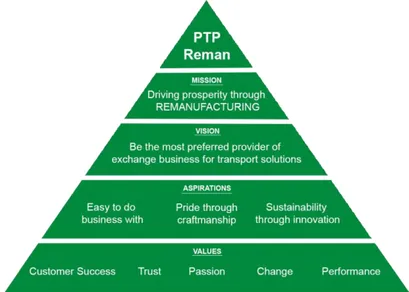
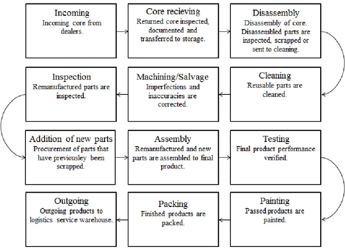
Figure 7 -Values, aspirations, vision and mission of Powertrain Production Remanufacturing. Figure 8 -Case company remanufacturing process.
Figure 9 -Marked area approximately 4x6 meter. Figure 10 -Picture of one of the disassembly areas.
Figure 11 -Current layout and movements within the disassembly area. Figure 12 -Virtual model workstation layout.
Figure 13 -Simulation model complete with photogrammetry.
Figure 14 -Number and placements of rocker arm shaft screws number 1-13. Figure 15 - Technical details of UR10.
List of tables
Table 1 -Disassembly sequence times and average. Table 2 -Activities and steps in HIRC design method.
Table 3 -Summary of how validity and reliability was assured. Table 4 -Simulation sequence order.
VI ABBREVIATIONS
Cobot Collaborative robot EU European union
FCC Fraunhofer-Chalmers Centre HAZOP Hazard Operability Analysis HIRC Human-industrial robot collaboration IMMA Intelligently moving manikins IPS Industrial path solutions
JSA Job Safety Analysis MDH Mälardalen University TCP Tool center point
1. INTRODUCTION
This chapter gives a brief background of manufacturing challenges, collaborative robot implementation and remanufacturing. Also, the projects problem formulation, aim, research questions and limitations made in the project are presented.
1.1 Background
European manufacturing plays a central role of the employment and economic growth for the countries within the European Union (EU) (European Commission, 2017). Over the past few decades it has been a decrease in European manufacturing with advantage for manufacturing in countries outside Europe e.g. China (Bennett, 2014). The manufacturing industry faces a competitive future and the challenges to meet are many. Today´s consumer demands more customized products. Along with this, the complexity of the products increases which means the manufacturing companies must be able to rapidly produce new products to a low volume (Thomas et al., 2012; Sundin and Dunbäck, 2013). The increasing global competition together with natural resources scarcity and customized, more complex products places higher demands on developing more cost effective, flexible production systems to be able to meet those new requirements (Bernard, 2011). At the same time, one of the greatest future challenges that manufacturing companies are facing is the environmental issues which includes the fact that the natural resources are finite which causes increasing prices on raw material for
manufacturing (Thomas et al., 2012). An overall objective for EU environmental legislation is sustainable development due to the need to limit climate change. There are several ways of achieving this where reducing energy consumption and carbon dioxide emissions are just two examples (2012/27/EU; Thomas et al., 2012).
Remanufacturing can be a way for European countries to maintain production and stay competitive (ERN, 2015). The future challenges make the remanufacturing industry environmentally beneficial in the way that compared to new manufacturing the
remanufacturing industry consumes less energy. Also, remanufacturing means less use of raw material, reduction of carbon dioxide emissions and less material for land fill (Bennett, 2014; ERN, 2015; Sundin and Dunbäck, 2013). There are more advantages of remanufacturing. From a customer perspective, it means a lower cost for a product that meets the same quality
requirements as for a newly produced product (Sundin and Dunbäck, 2013). The
remanufacturing process can be simplified described by incoming products are cleaned and disassembled and the parts that can be renovated are renovated and the parts which are too damaged to renovate are being replaced with new spare-parts before the parts are assembled to the final product (Priyono et al., 2015; Zhang et al., 2017). Even though the remanufacturing industry has a lot of beneficial aspects the industry is facing challenges. The consumers requirements of unique products and the finite natural resources bringing new materials to the market places higher requirements for remanufacturing production system with respect to flexibility. Customized products and new materials require that the production system needs to be able to handle adaptable and reconfigurable products but at the same time not compromise with lead time (Thomas et al., 2012). Another issue for remanufacturing is the human safety, mental and physical health (Matsas and Vosniakos, 2017). The importance of develop a
8 workplace were humans are kept safe at all-time must never be neglected (Ibid). Work-related injuries due to vibrations, repetitive movements and ergonomic problems are still ongoing issue that requires further improvement at many companies (Arbetsmiljöverket, 2017, 2018).
Automation of manufacturing by implementing robots can be one way to meet the demands of a more flexible production system and provide a safe work environment. The robot's flexibility and great precision along with repeatability make the robot an important tool in the company's competitiveness (Fryman & Matthias, 2012; Wang et al., 2017). The development of the robot's work situation has proceeded from working in an enclosed part of the factory to today being a partner that shares workspace and tasks together with an operator (Robla-Gomez et al., 2017). These kinds of workstations are called human-industrial robot collaborative systems (Ore, 2015). Those collaborative robots, which are called cobots, are beneficial since they can cooperate with an operator and perform the tasks that the operator should not perform due to e.g. ergonomic issues, safety risk or work injury that arises of e.g. repetitive movements (Robla-Gomez et al., 2017). The cobot may also contribute to time saving and quality
improvements (Fryman and Matthias, 2012). The cobot´s characteristics together with human's flexibility, which is an advantage when handle unforeseen situations, makes a good
combination as their characteristics complement each other (Wang et al., 2017).
Interaction between human´s flexibility and cobot´s characteristics can be seen as an enabler (Wang et al., 2017). Several studies have been made in cobot implementation in assembly stations where subjects like human safety, capacity utilization, cost, quality and time potentials, social acceptance and interaction between cobots and humans has been investigated, just to mention a few (El Makrini et al., 2018; Gualtieri et al., 2018; Müller et al., 2014; Sadrfaridpour & Wang, 2018; Wang et al., 2017). This makes the research of cobots in assembly stations relatively well investigated. However, for cobot implementation within disassembly in remanufacturing the search for theory and knowledge showed deficiencies within the field (Casper and Sundin, 2018; European Commission, 2017).
Compliance with legislation and standards together with a risk analysis of the specific case constitute the guidelines in the design of the station (Ruiz Castro et al., 2018). To find out the optimal design of a disassembly station with a cobot and an operator a simulation tool can be used. By using simulation software, the risk assessments of the human-robot collaborative workstation may be done in a safe and cost-effective way before implementing it in the production system. The possibility of simulating different scenarios enables to investigate different aspects of the outcome before implementing it to the physical station (Ore, 2015). The simulation program can contribute to decision making because the possibility of changing various factors to try different options is easy to make an can be tried out to a small cost (Bangert, 2013). Despite the advancements made, there are still several challenges related to the simulation of disassembly stations using cobots.
1.2 Problem Formulation
Even though the implementation of a cobot means that employees may be released from unhealthy tasks new challenges have appeared (Robla-Gomez et al., 2017). The new way of working, with the cobot working without fences, together with the human, requires a lot from a safety point of view. Although there are safety requirements according to laws and regulations that have been developed over time and which are to be followed, each workstation that
particular station (Fryman and Matthias, 2012; Inam et al., 2018). Implementation of a cobot may cause redesign of an existing workstation. Several factors need to be considered when implementing a cobot within an existing disassembly station (Vavra, 2016). One important aspect is to ensure the correct and safe cobot operation to avoid injuries to operator, other objects and the cobot itself as well as planning for optimal performance of the cobot (Inam et al., 2018). Using trial and error for risk assessment can be costly, dangerous and time
consuming (Ibid). Therefore, risk assessment should be made before implementation of the cobot. In addition, also, it is significant to plan for cobot´s optimal performance in terms of quality, time and cost (Ruiz Castro, 2018).
For remanufacturing companies, the disassembly process of the production systems comes with several challenges (Casper and Sundin, 2018; ERN, 2015; Lundmark et al., 2009). While assembly stations in manufacturing companies are automated at a high level the disassembly process in the remanufacturing industry is to a higher degree manually (Lundmark et al., 2009). Uncertainty of the condition of the incoming products is something that the manufacturing assembly does not need to consider but for remanufacturing this is an everyday issue (Casper and Sundin, 2018; ERN, 2015). While both manufacturing and remanufacturing companies are struggling with increasing numbers of product variants most products are designed for
assembly with little or no regards to disassembling (Casper and Sundin, 2018; Lundmark et al., 2009). In addition, parts are not generally designed for surviving neither disassembly nor remanufacturing e.g. newer materials may be impossible to remanufacture (Casper and Sundin, 2018). Also, there is a high risk of receiving contaminated incoming products (Ibid). The differences of aspects to consider in assembly and disassembly may make it difficult to directly apply all the knowledge that the research in assembly stations has found and use it in
disassembly stations.
As highlighted previous, the implementation of a cobot within a work station demands risk assessment for human safety and ergonomic aspects (Lasota et al., 2017; Robla-Gomez et al., 2017). Because of the many aspects that need to be considered for this, e.g. decision making when considering layout suggestions for the human-robot collaborative workstation or deciding who of the operator and the cobot to perform which tasks, the number of possible scenarios can be considerable (Bangert, 2013; Ore et al., 2017). Because of this a simulation can
advantageously be done (Banks, 2000).
Simulation modeling comes with challenges. The reality is complex and there may be several factors that can affect the outcome of a real world scenario. A simulation is a model of reality which means that there is no need to create a digital twin. The difficulties are to decide what to include and exclude in the model (Robinson, 2017). This leads down to the problem of how to secure validity and verification of the simulation (Banks, 2000). Also, data collection and designing the simulation model can take a lot of time (Sargent, 2013a).
1.3 Aim and Research Questions
Due to the many aspects to consider in cobot implementation and the challenges found within disassembly processes, the purpose of this thesis is to facilitate the design of a disassembly collaborative workstation by means of simulation.
To fulfil the purpose three research questions have been formulated
10 2. What are the advantages and disadvantages of implementing a cobot in a disassembly
station?
3. How can simulation be used to facilitate decision making when developing a collaborative workstation?
1.4 Scope
This thesis work is a part of a research and innovation project and explores how a simulation of a human-robot collaborative workstation layout and a dismantling sequence can contribute to critical decision regarding verifications of accessibility, analysis of the task sequence and the distribution of tasks between operator and cobot with respect to operator physical safety and cobot reachability when designing the collaborative disassembly station. The simulation explores the operator's and cobot's movements during the disassembly sequence, with the operator's safety considered.
A case study was made at an existing disassembly work station in a remanufacturing company in Sweden. The project work was performed during 20 weeks from the middle of January until the middle of May 2019. The case study focuses on the dismantling of a certain sequence and does not consider the process steps before and after the specific disassembly sequence. Safety standards that have been considered during this project are SS-EN ISO 12100:2010, SIS-ISO/TS 15066:2016, SS-EN ISO 10218-1:2011 and SS-EN ISO 10218-2:2011. The standards are further described in section three.
The virtual model was made in Industrial Path Solutions (IPS) which is a simulation software made by Fraunhofer Chalmers Centre (FCC). The robot used in the software is the Universal robot UR10. The robot´s technical specifications can be seen in appendix A. The choice of using IPS software was made before the project work with the thesis began and was taken by the project group. Limitations made in the virtual model can be seen in section 2.4.
The theoretical framework includes the subjects collaborative robots and safety aspects, advantages and disadvantages of collaborative robots, remanufacturing, disassembly, safety standards, simulation and risk assessment.
2 RESEARCH METHOD
The following chapter presents description of the research method and how the thesis was carried out. Additively a section for how data was collected and analyzed is represented. The chapter ends with a discussion about validity and reliability of the thesis.
2.1 Research Design and Research Method
Kothari (2004) highlights the importance of using a scientific method since it is a way to, by logical considerations, objectiveness and empirical evidence, build on already established scientific facts. The main research method for this thesis was case study. Case study is suitable as method for this thesis because as Merriam (1994) stated, case studies are preferable to use for qualitative studies and can be used to make a deeper investigation of a specific, strictly delimited situation, phenomenon, system or process. Case study is a deeper qualitative research method which means that the researcher tries to find out the complexity of the specific case and determine the impact of various factors (Voss et al., 2002). Several different research tools can be used in a case study. A case study is a representation of reality which can contribute to enriched knowledge (Kothari, 2004). Caution should be taken when generalizable conclusions are made from one single case study (Ejvegård, 2003). For this thesis, case study is chosen as a method for investigation since this choice provides the opportunity for a deeper investigation of the influencing factors in the single case. For this thesis the case study was made at a
disassembly station at a remanufacturing company where the examination of the disassembly process and the challenges met were made.
Simulation is a cost-effective way to try out different scenarios. Simulation can advantageously be used to provide understanding and identify constraints (Banks, 2000). Therefore, simulation was chosen as a method to fulfil the purpose of the thesis. To avoid incorrect conclusions, the simulation must be a well-balanced approximation of reality (Law, 2009). Kothari (2004) explains that a simulation method can advantageously be used to investigate a future scenario which gives an understanding of the future.
2.2 Research process
For case study method the research process can be divided into different steps consisting of choice of topic where defining research problem and purpose are included, review concept, theories and previous research findings, design research, choice of methods, collection of data, analysing data, interpret and report (Ejvegård, 2003; Kothari, 2004). Following the
recommendations above, the choice of topic was set as automation and specified as a collaborative robot disassembly work station. The research problem was formulated as the design of a disassembly workstation where operator´s safety and cobot reachability should be considered.
To summarize and get an overview of previous research findings a literature review was made by searching for articles and books at Mälardalen University´s network login Primo. Keywords used for the search was cobot, collaborative, HIRC, human, remanufacturing, robot and safety. This was made because as Kothari (2004) says, before stating the problem it is of importance to the researcher to identify previous research findings and find out if there are any theoretical shortcomings in the literature. Karlsson (2009) agrees with this and adds that the literature study of previous research findings should cover a wider range to give a broader perspective on
12 the subject to the researcher. The literature review of previous research findings and
discussions with school supervisor contributed to understanding the problem. Because as Kothari (2004, p. 12) says “the best way of understanding the problem is to discuss it with one´s own colleagues or with those having some expertise in the matter”. Afterwards, the problem formulation and research questions were developed.
To investigate the problem further the case study and the literature study was made parallel. The purpose of the literature study is to gather knowledge about what has been done in the subject up to now (Höst et al., 2006). By examining what others have done within the subject and adding new knowledge, it will contribute to the project work (Ibid). The purpose of the literature study was to gather knowledge about state of the art within the subjects simulation, remanufacturing and collaborative robots. Literature included books, international standards, conference proceedings and academic journals. Databases used for search was PRIMO and Scopus and were reached via Mälardalen University´s network login. Following keywords were used, separately or in combination, advantages, challenge, cobot, collaborative, decision
making, disadvantages, human, industrial path solutions, IPS, process, remanufacturing, risk assessment, robot, safety and simulation. All articles used were peer reviewed. A selection was
made by reading abstract to select articles that were relevant for this project. Some relevant articles were found in the reference list of selected articles and used as a source. The method is called snowballing. The literature study contributed to the theoretical frame of reference. Data collection was based on the case study with the purpose of gather data for designing the workstation virtual model and simulation input. The empirical findings and the theoretical frame of reference relationship led to analysis. Data collection for primary data can be
collected by e.g. observations or interviews, structured or non-structured. Secondary data is the data collected by others which includes articles and books. For secondary data the researcher must carefully consider the information reliability (Kothari, 2004; Yin, 2007). To be able to answer the research questions analyse of theory, simulation and empirical findings were made. The design of the workstation and the simulation were thoroughly analysed. Conclusions and recommendations were drawn from the analysis. Finally, conclusions and recommendations for further research were proposed. The research process that has been followed is visualized in Figure 1. The process is illustrated as a sequential process but has been followed in a more iterative manner.
Figure 1: Research process based on Kothari (2004)
2.3 Data Collection
The data for this thesis is based on a single case study. The case study was made at a disassembly workstation at a Swedish remanufacturing company. The collected data for the case study were gathered by passive and active observations, non-structured interviews and discussions. Those interviews, observations and discussions were made with representatives for the company and the project group for data collection and decision making regarding the virtual model´s layout, sequences and process. Yin (2007) says that for collection of
information, interviews are of great importance to the case study. Gagnon (2010) points out the importance of using several different sources for data. Both Gagnon (2010) and Yin (2007) says that this is a way to secure validity and reliability to the case study. Data collection was made to be able to design the workstation and make the simulation of the disassembly sequence.
2.3.1 Discussions
Proper interpretation of research findings is crucial for usability and usefulness. For the less experienced researcher interpretation is with advantage discussed with more experienced people who have insight in the case study (Kothari, 2004; Yin, 2007). Therefore, during the project work discussions have been made with representatives from the company who brought valuable knowledge about the case study and representatives from the project group since their experience and knowledge about collaborative robots added value to the project work. Also, discussions and advices derived from school supervisor because consulting experts are to prefer
14 when writing the report as well as for advice and guiding (Kothari, 2004). Discussions with the representatives of the company were held daily and topics such as placement of the robot, disassembly sequence order, disassembly process, task allocation as well as challenges in disassembly within remanufacturing and specific information about the company were raised.
2.3.2 Observations
As input for simulation a time study was made at the current disassembly work station. The purpose of the time study was to use it as a reference time for the simulation. Three time-study observations were made for the disassembly sequence. The disassembly sequence was the disassembly of 13 rocker arm shaft screws. The rocker arm shaft screws were one M14 and twelve M10 and can be seen in Figure 2. The time study was made when the operator started to loosen the first screw until all the screws were completely disassembled. The result of the time study of the sequence can be seen in Table 1. The averages of the time studies were used as reference time for the output of the virtual model, rounded to the nearest whole seconds. Notice that the disassembly sequence is performed by one operator only.
Figure 2: D13 engine with 13 rocker arm shaft screws Table 1: Disassembly sequence, times and average
To find out the locally challenges of the disassembly station active observations for two days at the disassembly station took place. The active observations were held at the case company disassembly workstation with a skilled operator who guided the way thru the disassembly process. The two-day observations included execution of the dismantling of three products. The active observations at the disassembly station contributed to a deeper knowledge for the
disassembly process, primary data collection and discussions with the operator about challenges within the disassembly process. Observations were documented with field notes. Advantage of active observations is the possibility of gathering inside information and knowledge that might be difficult to find out in another way (Yin, 2007).
Disassemble of Time 1 Time 2 Time 3 Average
2.3.3 Interviews
Non-structured interviews were made with representatives for the company. The interviews provided knowledge about challenges within remanufacturing in general and disassembly in particular. It contributed to a clear picture of today´s greatest challenges of the disassembly process at the company. The interviews were made with four people at the company. Two operators at the disassembly station were interviewed about the disassembly process at the company. The interview was made for about 30 minutes and field notes were taken. A
production engineer and a remanufacturing engineer/technical trainer were interviewed about the remanufacturing process at the company, challenges about remanufacturing and the
disassembly process. For those interviews field notes were made as well and the time spent for the interviews was 20 minutes each. The interviews were made at the company. The questions asked can be seen in appendix B.
2.3.4 Meetings and mail contact
Two skype-meetings were held with two IPS simulation software experts. Also, a weekly mail contact was established with the two experts. The purpose of the meetings and mails was to bring more knowledge about the software and expert advice about how to build the simulation model. Mail contact and weekly skype-meetings has been held with project group
representative. The purpose of the mail and meetings were to provide the project group representative with information about how the work with the thesis progressed. Also,
information about how to perform the photogrammetry was conducted during a skype-meeting with a skilled photogrammetry person.
2.3.5 Documents
For the virtual model made in the simulation software, CAD-models for UR10 robot, engine positioner, the D13 engine, table, boxes, manikin- and cobot tools was used. The CAD-models provided the virtual model with correct dimensions and proportions. For the manikin the default male manikin was used because this represents the average height and weight of a male person. The default manikin in IPS software has a weight of 78 kg and a height of 1756 mm. Although the software offers a female manikin, the male was chosen as there are 82% male employees at the company. The accurate dimensions of CAD-models and manikin increases validity since this data are not created as a result of the case study (Yin, 2007). A
photogrammetry was made at the physical disassembly station at the case company and the result was used as a background for the virtual model with the intention of visualizing a real-life scenario to the viewer. The result of the photogrammetry can be seen in Figure 3.
16
Figure 3: Photogrammetry of current work station layout
2.4 Simulation
The software used for designing the virtual model is called Industrial Path Solutions (IPS). It is a simulation software developed by Fraunhofer-Chalmers Centre (FCC). IPS consists of several modules. Used in this project was the intelligently moving manikins (IMMA) module, rigid body path planner module, point cloud tools module and robot optimization. The IPS software was a choice of the project group. The software is developed to evaluate ergonomics, assembly feasibility and motion planning. The software is still under development (FCC, 2019). A manikin is a model of a human body. In this thesis what refers to as a manikin is the human model of the operator in the IPS simulation software. The IMMA module finds collision free paths for the manikin movement. This enables the opportunity to change the manikin´s
movements along the modelling phase to choose a safe, collision free path for the manikin. The same is applicable for the robot optimization module. If the program is unable to find a
collision free path for the robot there will not be a solution which means that the creator will redo the model until a pleasant solution can be found.
Banks (2000) states that each simulation model is unique and each creator of simulation-models require knowledge within and practice to learn the software to make a proper analysis of the outcome. Therefore, as a start up a short introduction to the IPS simulation software and eight weeks of part-time study to learn the software took place. The introduction was held during one day with an IPS simulation-software experienced person. After the eight weeks start-up period a virtual-design model of the workstation future state was made in IPS
simulation software. The purpose of the model was to simulate a future scenario where a cobot and an operator, through collaboration, disassembles parts of an engine and with the help of the simulation model be able to answer the research questions. The analysis of the simulation would determine the workstation layout and evaluate the operator and the cobot movements with respect to operator´s safety.
The method used for designing the simulation is called the Human-industrial robot
collaboration (HIRC) design method which is a linear process made by Pahl and Beitz (2007) engineering design method and further developed by Ore, Hansson and Wiktorsson (2017). The activities of the method are visualized in Figure 4. Input for using the method is a workstation, with geometrical boundaries, that can benefit from a robot.
Figure 4: HIRC design method by Ore, Hansson and Wiktorsson, (2017)
Table 2 shows an overview of the method steps and which actor completed the steps. The first and partly the second and third step of the method which consist of activities like a first rough analysis of the work station and determine what robot to select was already made by the company before the work with the case study began. The remaining steps were completed by the author and will be described below.
18
Table 2: Activities and steps in HIRC design method
Activity Steps Completed by Identified potential HIRC
workstation
• Identify HIRC workstation. • Company Planning and clarifying
the task
• HIRC possibilities of investigated workstation. • Analyse company-specific demands on workstation. • Formulate evaluation criteria and design variables. • Set evaluation criteria and design variables. • Elaborate a requirements list.
• Author/Co mpany • Author/Co mpany • Author • Author • Author Requirement list • Result from previous steps. • Author Conceptual design • Identify essential problems. • Author Principal solution • Principal solution. • Author Embodiment design • Preliminary design of HIRC workstation.
• Refine and improve HIRC workstation design. • Find and solve errors and weak spots.
• Prepare the preliminary HIRC workstation documentation.
• Author • Author • Author • Author Definitive solution • Definitive solution. • Author Detail design • Detail evaluation and adjustments of the resulting
documentation.
• Author Workstation
documentation
• Workstation documentation. • Author Workstation design • Workstation design. • Author
Decision about chosen variant of the industrial robot was set by the project group before the project work with the master thesis began. The collaborative robot used in the virtual model was the Universal robot called UR10. The reachability of the UR10 is 1300 mm with a payload capacity of 10 kg. The cobot has six degrees of freedom and a repeatability of ± 0,1 mm. The cobot´s full technical specification can be seen in appendix A. For human safety the UR10 comes with built-in safety systems. It is designed to be user-friendly with a built-in force sensing system which makes the cobot stop when obstacles occur and the cobot can be
controlled to operate at a lower speed as a human enters the work area. The UR10 cobot is easy to program and does not require expert knowledge in programming. The UR10 cobot supports hand guiding which means that the cobot can be programmed by physically moving the cobot arm to show what to perform (Universal robots, 2019).
Evaluations according to operator and cobot’ operation time was made by a time study. Design constraints regarding cobot´s maximum payload, reachability and manikin anthropometry was set. A requirement list was the result of the first six steps. A literature study was made to gather more knowledge about not only collaborative robot workstations but also laws and regulations to bring a deeper understanding of what to include in the virtual model. A conceptual model of a simulation is a description of the simulation to be (Robinson, 2017). To summarize and get an overview of the simulation model a conceptual model was made. The conceptual model
includes problem definition, general objectives for the simulation model, assumptions and limitations, input and output since those steps are suggested by Robinson (2017). The
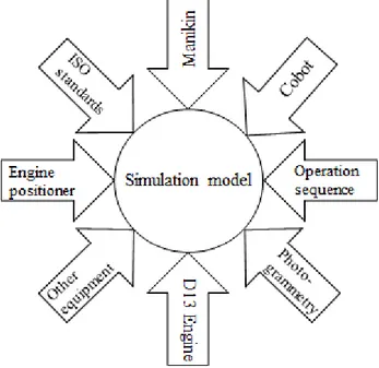
conceptual model can be seen in appendix C. Input for the conceptual simulation model can be seen in Figure 5. A documented conceptual model is recommended since it contributes to increase credibility of the model and set the right requirements for the simulation model (Robinson, 2017). A first design of the virtual model was made based on the discussed requirements. The model was evaluated together with representatives from the company. Documentation about the virtual model was made during the work. Discussion was made
within the project group to find the best principal solution. A text document about the
simulation sequence order was made and evaluated by representatives from the project group.
Figure 5: Input for simulation model
With the knowledge from the literature study and the data collection the building of the virtual model started with the creation of the virtual model´s station layout. As a start two different layout proposals for the future layout were made with IPS software. The layout proposals were evaluated together with representatives from the company and the project group. Discussions regarding a first position of cobot, cobot tools, placement of materials and equipment were made. The building of the disassembly sequence and decisions regarding the sequence order were made in agreement with representatives from the company and project group. The ISO standards set requirements for the simulation. As an example, the velocity of the cobot´s tool center point (TCP) shall not exceed 250 mm/s in a reduced mode (ISO, 2011). Kinematic is used for the moving objects in IPS simulation. The use of kinematics allows the software to set restrictions on how the robot's joints can move in relation to each other (FCC, 2019). The description of how the simulation were made can be read in section 4.1.6. Decisions about what parts to include in the disassembly sequence in the simulation were taken during discussions with company representatives. A screw joint, the rocker arm shaft screws, were selected to be disassembled in the simulation. The choice of the screw joint was made because of the
ergonomically difficulties that occur during dismantling of the screws and because of the vibrations from the tool that, in a long-term perspective, are affecting the operators in a negative way.
Limitations made within the virtual model:
• One operator and one cobot were considered at the work-station. • Robot brand and model was already defined as the project work began. • The default manikin was decided to represent the operator anthropometry. • The simulation presents a disassembly sequence of a screw joint.
• Operator safety is considered. In this thesis the definition of operator safety is limited to the physical aspect of safety which means that the operator should not be exposed to situations where physical damage may occur. In the study no account has been taken of operator´s ergonomics or psychical safety.
20 • The virtual model is a simplification of reality and does not include simulation of
vibrations from tools, contaminated or missing parts even though this is common challenges within disassembly processes.
2.5 Data Analysis
Data analysis is a critical part of a case study. Unfortunately, it is one of the least developed parts (Yin, 2007). This thesis work followed Gagnon (2010) suggestions to organize and identify the literature, categorize and code it. With the research questions in mind the literature was read and relevant parts were highlighted. The sortation and highlighting were made to ease the comparison of the literature. Key terms was identified which made the collected literature to be sorted by subject. The subjects were remanufacturing, collaborative robots and
simulation. Within the subjects remanufacturing and simulation the highlighted parts was
coded as advantages and disadvantages and for the subject collaborative robots the highlighted parts was coded as safety and other. The highlighted parts were sorted in a spread-sheet with the subjects as headings and with authors, note and code as subheadings.
Gagnon (2010) says that the correct data collection and analyse must be made to be able to use it for certain software. The collected CAD-models for the simulation was confirmed correct by measurements. The IPS software made it possible to start the analysis at an early stage in the modelling phase since the software finds collision free paths for the manikin and the cobot. Merriam (1994) states it; analysis of a case study is an iterative process that is going on during the project period. As the building of the simulation proceeded it was presented on a weekly basis to the representatives of the company with the purpose of receiving feedback. The
feedback contributed to improvements for the simulation. Analyse of the simulation model was made iteratively as the work with the model proceeded. Cobot reachability and collision free paths for cobot and manikin was analysed in IPS software.
The design of the workstation and the simulation was used to verify reachability for the cobot and the manikin and to determine station layout. The physical station´s limitations together with cobot´s reach contributed to the cobot´s placement on top of the engine positioner in the virtual workstation layout. Several different placements for the cobot was tried and discussed with the company representatives and with the project group before the final position was determined. The cobot´s reach limited parts of the operation sequence which caused predetermined task allocation for cobot and manikin. This limitation was found during analysing the simulation model. The final solution for task allocation and operation sequence occurred because of cobot’s reachability limitations and during discussions with project group and company representatives. Also, IPS software comes with limitations. The final virtual simulation model is made based on the limitations and boundaries that have been made within the case.
Gagnon (2010) proposes to analyse the empirical findings by writing a case summary and let a person of interest read it. The person of interest should confirm whether or not the summary reflects the reality of the case. For the thesis work a summary of the case was written and a representative of the company confirmed coherence to reality. Yin (2007) explains pattern matching as an analytical tool where empirical findings are compared with an expected pattern. The empirical findings were compared with theoretical findings derived from the literature study and similarities were confirmed. Measurements were done to verify the data collected from the disassembly station.
Analyses to be able to answer research question number one was made by examination of the possibilities of the IPS software when designing the simulation model. During skype-meetings and mail contact with IPS software experts knowledge about how the software could be used and what parts of the research questions that was possible to answer. Literature about
simulation modelling, the IPS software, human safety and collaborative robots and the
technical specifications and characteristics of the UR10 robot was read. The literature and the simulation and the similarities within were compared. For research question number two derived theory were compared with answers from interview questions. Similarities between theory and empirical findings were identified. The simulation sequence, theory about
simulation, IPS software, UR10 robot, ISO standards, human safety and collaborative robots and information gathered by skype-meetings with IPS simulation experts were compared and similarities was found for the third research question.
2.6 Validity and Reliability
Validity and reliability is how to ensure the correctness of the study. Validity means to ensure that the right measurements are made, that the right tool is used for the right task. Reliability is to ensure that the measurements are made in the right way, to ensure accuracy for
measurements made. A high validity requires high reliability, but a high reliability does not necessarily mean high validity (Kothari, 2004). Yin (2007) points out construct validity, external- and internal validity and reliability as design criteria to be used for case studies. Construct validity is to assure the right measurements are used for intended measures (Yin, 2007). Voss et al. (2002) mentioned that increase construct validity can be made by finding convergence from several different sources. Yin (2007) says that construct validity can be achieved by triangulation and by letting persons with insight in the case study read the thesis draft. For this thesis triangulation has been used for data collection. This has been made by comparing the multiple data collected by literature study, observations, interviews, discussions, meetings and mails. The comparison made resulted in found similarities within. School
supervisor and project group member has been reading the thesis draft to critically inspect the accuracy of the content.
External validity means that the study's conclusions should be generalizable (Voss et al., 2002; Yin, 2007). In this thesis this was made by the empirical findings that include collection of data from multiple resources and comparing the findings with findings in the literature study.
Kothari (2004) and Ejvegård (2003) say that to ensure generalizable conclusions evidence should be found by other research methods or case studies as well. For single case studies there is always a risk for bias (Voss et al., 2002). An advantage of a single case study is the ability of observing and analysing the case in detail (Yin, 2007). This thesis is made by a single case study which should be taken into consideration when generalizable conclusions are made. The similar findings which were found in the literature study and supported the empirical findings increased the external validity of examined case.
The internal validity is achieved when case study findings corresponds with theoretical evidence found in literature which makes the findings generalizable (Gagnon, 2010). Voss et al., (2002) say that to achieve internal validity triangulation can be used. Triangulation has been made with interviewing different stakeholders comparing the answers. The work with the case study and the writing of the thesis was made at the company. The closeness to the
22 and other company representatives which enables to iteratively verify and confirm collected data and control the results.
Reliability is the use and documentation of methods. The purpose of ensuring reliability is that another person should be able to perform the very same study, using the very same methods and achieve the same result (Yin, 2007). Reliability has been increased using well documented, scientific methods. A summary of how validity and reliability was ensured can be seen in Table 3.
Table 3: Summary of how validity and reliability was assured
Design criteria Application Applied
Construct validity Triangulation, feedback from stakeholders Data collection External validity Theoretical reference Research design Internal validity Triangulation Data analysis
3 THEORETIC FRAMEWORK
This section highlights the theoretical findings within the topics remanufacturing and collaborative robots and their safety. Theory is derived from books, conference papers and journal papers.
3.1 Remanufacturing
In this thesis, the definition of remanufacturing that is provided by the British standard Institution's BS 8887-2: 2009 Terms and definitions are used. Cited by ERA (2015, p.4) the definition states: “Returning a product to at least its original performance with a warranty that is equivalent or better than that of the newly manufactured product.”
Additionally, disassembly, restoring and replacing parts of the product to achieve condition as new.
The world's natural resources are limited. Price of raw material increases as the natural resources decreases. That and the fact that energy consumption arises globally makes circular manufacturing important. Remanufacturing not only saves natural resources but also uses less energy consumption compared to new production. Also, it reduces landfill, as old products are renovated and restored to be as good as new instead of being discarded. A study made by Zhang et al. (2017) showed that company drivers to remanufacture are morally, ethically, profitability and environmentally established. Remanufactured products are sold at a lower price and cost less to produce compared to products from new production, which results in a win-win situation as both customers and the environment benefit from this (ERN, 2015). Remanufacturing process differs from manufacturing process in the way that remanufacturing process includes disassembling and cleaning of the incoming products (Lundmark et al., 2009). Even though remanufacturing is beneficial in many ways also it comes with challenges.
Modern manufacturing places high demands on flexibility and safety. The remanufacturing industry is currently facing increased demands for flexibility in their production because of increasing variations of products (Casper and Sundin, 2018). Lundmark et al. (2009) highlights challenges like product quantity-, quality- and timing-uncertainty along with complicated disassembly sequences. In addition, the authors says that remanufacturing of a certain product demands more labor than manufacturing for the very same. Moreover, the authors state that remanufacturing has a lower degree of automation than manufacturing does. ERN (2015) displays three challenges for the remanufacturing industry to overcome where process
technologies are one of them. Production planning may be difficult since there is uncertainty of incoming products (Lundmark et al., 2009).
The remanufacturing process starts with an incoming, used product, known as cores. The product are being cleaned and inspected before the disassembling of the product starts. The inspection goes on as the disassembly process progress. Damaged parts are being
remanufactured and parts that are too damaged to be renovated are being recycled. The remanufactured parts are being assembled with new parts and the assembled product is being tested before delivered to customer (Lundmark et al., 2009; Zhang et al., 2017).
3.1.1 Disassembly
The disassembly sequence of the remanufacturing process comes with some challenges. Not only are the great variety of the products a challenge but also it is not uncommon that two
24 identical products are very different when it comes to how many parts of the product that can be remanufactured (Lundmark et al., 2009). Casper and Sundin (2018) says that one of today´s challenges in remanufacturing are the uncertainty of the condition of the incoming products since parts can be missing and screws, nuts and bolts could have been tightened with varying results. This uncertainty demands further inspections as the disassembly goes on. The high risk of contaminated incoming products complicates the disassembly process even more. Lundmark et al. (2009) discuss the issue that products usually are not designed for disassembly. Because of this product may be damaged when disassembled (Priyono et al., 2015). Also, this issue causes great variances in required disassembly time which makes it difficult to set accurate lead-times (Lundmark et al., 2009). Moreover, how successful the disassembly process is are depending on the skills of the operator as well (Priyono et al., 2015).
3.2 Advantages and Disadvantages of Collaborative Robots
Robots have been an important part of the industry for decades. The automation of the industry has added quality, speed and reduced costs (Vavra, 2016). The top five reasons to automate are, according to Vavra (2016), improve throughput, reduce direct labour costs, improve product quality, improve worker safety and reduce overall footprint. Müller et al. (2014) describes the human-robot collaboration as a factor that increases productivity and efficiency, in addition, the collaboration enables customized production. Gopinath et al. (2017) say that collaborative robots are beneficial for humans since they can perform tasks that would be repetitive and unergonomic for a human to perform. Wang et al. (2017) agrees with this and adds the fact that robots are excellent at performing work that requires precision. Fryman and Matthias (2012) and Ruiz Castro et al. (2018) agree with former authors when they say robots are a good complement to the human workers. Also, the authors states that robots are good for work that requires high quality and can be beneficial in several ways when taking over tasks that may be a risk for a person to perform. The development of collaborative workspace contributes to improvements in quality and flexibility as humans can take fast decisions in real time (more flexible) and robots are good at performing precise, repetitive tasks (Ruiz Castro et al., 2018). The conventional robots that work enclosed by the fence occupies floor space. The
collaborative robots enable a reduction of this floor space because a cobot´s work area also includes the human work area (Fryman & Matthias, 2012). This contributes to cost savings as both human and robot uses the same area (Grahn et al., 2016). The collaborative robot has some of the same advantages as the regular robot working within fences by that means they can work without breaks and has a high process capacity (Müller et al., 2014). Moreover,
collaborative robots can be used as a lifting tool which enables reduce cost as lifting tools can be eliminated (Grahn et al., 2016).
An experiment with developing a manual work cell to a collaborative robot cell by Cherubini et al (2015) showed a decrease of strain injuries risk. Wang and Zhang (2017) examined human-robot collaboration within an assembly station. The authors believe that the benefits with a human-robot collaborative workstation are the human intelligence, additional observations and flexibility together with cobot´s characteristics. Wang and Zhang (2017) talks about human safety and determines that safety risk occurs because of human behavior uncertainty. They say that slowing down the cobot movements when a human is near is from a safety point a good view but for productivity a negative way of solving safety issues. The authors’ points out that both safety and productivity are important to consider.
A challenge when implementing collaborative robots to the industry is the human acceptance of interacting with a robot (Sadrfaridpour and Wang, 2018). Grahn et al. (2016) writes about a study where ten operators were asked about collaborative robots. The study showed that 30% of the respondents answered negative to robots working without fences. Over- and under-reliance between human and robot might lead to a decrease of performance outcome
(Sadrfaridpour and Wang, 2018). As humans entering the collaborative work-zone the robot cannot work at full speed. According to regulations the velocity of the robots TCP must be limited to 250 mm/s (Grahn et al., 2016). Inam et al. (2018) says that the operator should provide knowledge about robot behavior before collaborative work begins. Some robots require expert knowledge and a lot of time spent for programming. However, nowadays at the market, there are robots which are easily programmed by hand-guiding which does not require expert knowledge or take much time (Grahn et al., 2016).
3.3 Collaborative Robots and Safety
The development of the robots has gone from a robot working within fences, which secures the humans safety, to work collaborative with humans. A collaborative workspace requires
thorough safety consideration (Ruiz Castro et al., 2018). As stated above, robot´s accuracy and human´s flexibility makes the collaboration beneficial (Ibid). However, human flexibility is not exclusively positive because even though human-robot interaction safety is considered in the most meticulous way, humans tend to change their behavior in an unexpected way which makes it impossible to predict all possible scenarios when planning for robot motions (Wang and Zhang, 2017). This makes real-time motion planning important. Using task-based and geometric constraints simultaneously has proven to be beneficial. As an example, it can enable identification of areas where humans are most likely to move or identify configurations that are not solution-supporting. Other constraint fusion techniques exist as well (Lasota et al., 2014). Understandably, this development causes high demands on safety regulations (Wang, 2016). Also, safety regulation results in limitations in speed and force of the robot which means that the robot´s full capacity is not being utilized (Ruiz Castro et al., 2018).
The human should be kept safe in any conditions during interaction with the robot. For a safe human-robot interaction every station is unique and there are many aspects to consider. The design and layout of the workspace, robot system limits, risk reduction and task identification are just some aspects that Vavra (2016) mentions. Lasota et al. (2014) have written a summary of safe human-robot collaboration according to ISO/TS 15066. Their work covers papers about the human safety aspects written 2008-2015. The authors discuss control methods for robot motions and divide it into two categories: pre- and post-collision. The pre-collision methods addressed are quantitative limits, speed and separation monitoring and potential field methods. The two latter methods can be divided into two sub-categories each: safety zones and
separation distance, non-intrusive real time measurements, human features and robot features respectively. Quantitative limits mean limitations of robot parameters like joint velocity or force to prevent human injuries. Using static or dynamic safety zones and within those zones control the speed of the robot and the distance between robot and object is what the authors refer to as speed and separation monitoring. The safety-zones can be controlled by external sensing devices to track humans’ motions within the zone which makes the robot stop or slow down as human enterers the zone. The dynamic safety zone can be visualized with a projector. Vavra (2016) suggests painting the floor where the human-robot interaction takes place to easily visualize the interactive space to the operator. El Makrini et al. (2018) solved the safety issue, when implementing a cobot within the automotive industry, by using safety skin on the robot which enabled the robot detection of human contact. The authors used gesture and face
26 recognition for communication with the cobot. The implementation of the cobot led to reduced material consumption and improvements in quality. Wang (2016) presents a human safety system using depth images and 3D models for collision avoidance where the robot will move in another direction or stop if the human is at risk. The robot will continue its task as soon as the risk is eliminated. Wang (2016) continues by saying that the safety of the operators requires real time data for collision detecting as well as collision avoidance. Lasota et al. (2014) writes that the potential field method uses vectors to control the robot's movements to avoid real-time collision and planning robot motions considering human presence by using distance of
separation, robot motion legibility, reachability and human vision field and have been made successfully when improving safety in human-robot interaction.
Observed post-collision safety methods that are brought up by Lasota et al. (2014) are divided into collision detection, localization and reaction with the sub-categories non-collaborative contact, collaborative contact and evaluation and interactive control methods with the sub-categories detection of collaborative intent and interaction strategies. Post-collision control methods demand some kind of collision detection system. The authors present two methods were the system is capable of distinguish between intentional and unintentional robot
collisions. Also, for the reaction of the collision there are systems that make the robot react to a collision by move in another direction and then stop or modify its motion path. The authors’ highlights an experiment were human injuries caused by robots with sharp tools can be reduced. If the human are entering a collaborative mode the system must be able to know whether or not the collision is intentional and what part of the human body that the robot is allowed to be in contact with. This means real time evaluations and decisions which ends in reactions and requires sensors to function.
The workplace design must be made so it guarantees the safety of the human and prevents accidentally, dangerous collisions between robot and human (Gualtieri et al., 2018). Gualtieri et al. (2018) proposes to allow some of the space at the workstation to the robot alone where it will be able to work at full speed without the risk of human collision. The authors present an axiomatic design method for designing a collaborative workstation. Mateus et al. (2019) gives examples were cameras are used to let the robot detect objectives and movements in the surroundings. Mateus et al. (2019) states that there are further possibilities for human-robot collaborative work. The authors propose a methodology for design of a collaborative
workplace. The methodology uses information from product CAD models as a base to make a structure and combine this with the requirements of product assembly. This is used together with ergonomics of human and robot capability which sets a safe collaborative workplace.
3.4 Safety Standards
A human life must never be compromised. For a safe approach, safety standards, both general and robotic standards must be taken into consideration. There are several standards available. The following standards have been considered for this thesis:
• SS-EN ISO 12100:2010 Safety of Machinery -general principal for design –risk assessment and risk reduction.
• SIS-ISO/TS 15066:2016 Robots and robotic devices -collaborative robots. • SS-EN ISO 10218-1:2011 Robots and robotic devices -safety requirements for
industrial robots -part 1 robots.
• SS-EN ISO 10218-2:2011 Robots and robotic devices -safety requirements for industrial robots -part 2 robot systems and integration.
The international A-standard ISO 12100 provides tools for a safe design of machinery. The standard includes risk assessment and risk reduction (ISO, 2010). ISO 1 and ISO 10218-2 include guidelines and requirements for safe collaboration between human and industrial robots (ISO, 2011). ISO 15066 specifies safety requirements for collaborative robots.
3.5 Risk assessment
Risk assessment should be performed when developing a human-robot collaborative workstation (ISO, 2016). Inam et al. (2018) says that to ensure operator safety in a human-robot collaborative workstation it is not enough to use only ISO standards. To ensure operator safety risk assessment and risk reduction measurements shall be made (ISO, 2010). Risk reduction can be achieved thru safety rated monitored stop, hand-guiding, speed and separation monitoring and power and force limiting which are described in SIS-ISO/TS 15066:2016. The robot can work at full speed but when a human enters the collaborative workspace the speed of the robot shall be reduced. There shall always be a separation distance between robot and human. If this distance is below minimum value the robot shall stop. The lower speed the shorter separation distance is needed (ISO, 2016). The speed of the robot´s TCP shall not exceed 250 mm/s in a reduced speed mode (ISO, 2011). Formulas for calculations of minimum protection distance and total stopping time can be seen in SIS-ISO/TS 15066:2016 and SS-EN ISO 13855:2010 Safety of machinery - Positioning of safeguards with respect to the approach speeds of parts of the human body (ISO, 2010; ISO, 2016).
Gopinath and Johansen (2016) propose to use Job Safety Analysis (JSA) for risk assessment. JSA divides the task into subtask and risk assessment is made for those subtasks. The authors present a tool for safe hand-guiding of an industrial robot. Yamada et al. (1999) used Fault Tree Analysis (FTA) when identified hazardous situations that occurred at a coexistence human-robot system. The identified risk factors were set as human errors, outsiders entering the work zone and abnormal robot motions. Inam et al. (2018) made a case study using Hazard
Operability Analysis (HAZOP) for risk identification. The method uses a structured way to identify risks. Inam et al. (2018) points out the importance of robot behavior knowledge of the operator collaborating with the robot to be able to generate a beneficial, risk reduced
cooperation. Failure Modes and Effects Analysis (FMEA) is used in the design process to determine failure (Korayem and Iravani, 2008). Other methods for risk assessments exists as well (Inam et al., 2018).
3.6 Production system development
There are several different reasons why companies urge a need to develop their production system. Common reasons are mentioned by Bellgran and Säfsten (2010) as the need of increasing capacity, improving work environment, change in a product or the introduction of new products. The development process of a production system can be divided into steps like design phase, building the production system and evaluation of implemented solution (Ibid). The production system development process starts with the design phase were companies identifies their need of change and makes a current state analysis (Bellgran and Säfsten, 2010; Bruch and Bellgran, 2013). Another step of the design phase is to set the objectives (Ibid). In the design phase relevant information and data is collected (Bruch and Bellgran, 2014). Further on in the design phase the design of the conceptual production system is made and evaluated
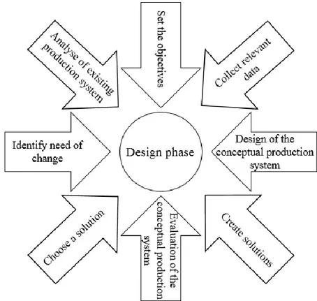
28 (Bruch and Bellgran, 2013). The design phase also includes to identify the requirements of how to proceed from current state to the objectives and choose a suitable solution (Bellgran and Säfsten, 2010). Different steps of the design phase can be seen in Figure 6. Bruch and Bellgran (2013) says the design process are an iterative process. The next step in the process is to implement chosen solution (Bellgran and Säfsten, 2010).
Figure 6: Different steps of the production system design phase made from Bruch and Bellgran (2013).
3.7 Simulation
The process of modeling a simulation is mentioned by several authors in different approaches. But the process is quite similar with steps like identify and formulate the problem, data
collection, develop conceptual model, build the simulation model, analyze validity, experiment and analyze results (Fowler and Rose, 2004; Skoogh et al., 2012; Steinemann et al., 2013).Law (2009)recommends talking to as many people as possible that is involved with the problem to obtain the very best understanding of it. He writes that it is of importance for the validity of the simulation model to formulate the problem correctly. The author continues by saying that correct problem formulation will lead to understand what data to collect. Skoogh et al. (2012) writes about the problem of collecting data that is accurate, valid, consistent and reliable as well as the problem of how to process and store the data. Robinson (2017) claims that the conceptual modeling part of the simulation process is the most difficult but also the most important. This is the part when to decide what to include and exclude in the model. Fowler and Rose (2004) say that too many details may not make the simulation model calculate a more accurate answer. Fowler and Rose (2004) means that the simulation model needs enough details to give correctly results but not so much that makes the model difficult to understand. Flexibility, less data collecting and easier to develop and understand is just some of the benefits that Robinson (2017) points out with a simpler model. However, Law (2009) says that it is
important that the model is a well estimation of the real system to be able to give accurate results. Most of the simulation models is made only for one specific case (Fowler and Rose, 2004; Steinemann et al., 2013). Law (2009) recommends testing the validity for each case the simulation model is used. Even though Law (2009) and Sargent (2013b) points out the
importance of the model being an appropriate approximation of the real scenario they both says that increasing validity may cost more than it will yield meaning that it might take a long time collecting new data and it doesn´t necessarily mean that it will increase the validity. Banks (2000) points out that two models made of the same process made by two different modelers is very likely to result in two different models. However, the result of the simulation should be analyzed thoroughly (Steinemann et al., 2013; Law, 2009).
A simulation is beneficial since it allows companies to try out different future scenarios without utilizing resources which can be done to both existing and non-existing systems (Banks, 2000). A simulation must not be a digital twin of a real case scenario. In fact, a simulation model is always an approximation of the reality (Law, 2009). But the simulation can be a way of considering and analyzing scenarios made from certain well-defined factors, which makes a simplification of reality. What factors to consider differs from case to case (Ore et al., 2017). Simulation can be used to examine future scenarios as well as existing production system e.g. bottlenecks (Banks, 2000). Everyday difficulties when building a simulation are correct understanding of the problem, setting the right objectives, correct data collection, verification and validation (Banks, 2000; Law, 2009). Banks (2000) says that simulation modeling may be time consuming and the art of simulation modeling takes time to learn. Knowledge and