B
UILDING AND EXPERIMENTALLY
EVALUATING A SMART ANTENNA FOR LOW
POWER WIRELESS COMMUNICATION
Erik Öström
eom02001@student.mdh.seMaster Thesis in Computer Science, 30p D-level
Mälardalen University
S
WEDISHI
NSTITUTE OFC
OMPUTERS
CIENCE
Thesis worker: Erik Öström 2010-05-05 Supervisor: Luca Mottola, Ph.D. Page 2 of 87
Thesis worker: Erik Öström 2010-05-05 Supervisor: Luca Mottola, Ph.D. Page 3 of 87
B
UILDING AND EXPERIMENTALLY
EVALUATING A SMART ANTENNA FOR LOW
POWER WIRELESS COMMUNICATION
Master Thesis
Erik Öström
eom02001@student.mdh.se 2009-05-08
Examiner: Prof. Mats Björkman Mälardalen University (MDH)
Supervisor: Luca Mottola, Ph.D.
Thesis worker: Erik Öström 2010-05-05 Supervisor: Luca Mottola, Ph.D. Page 4 of 87
Thesis worker: Erik Öström 2010-05-05 Supervisor: Luca Mottola, Ph.D. Page 5 of 87
This thesis work is accepted and approved by
SICS
Name:__________________________________ Date:__________________________________Mälardalen University
Name:__________________________________ Date:__________________________________
Thesis worker: Erik Öström 2010-05-05 Supervisor: Luca Mottola, Ph.D. Page 6 of 87
Thesis worker: Erik Öström 2010-05-05 Supervisor: Luca Mottola, Ph.D. Page 7 of 87
Preface
This thesis is the final work of my Masters Degree in Robotics. The work was performed at SICS in Kista (Stockholm) and graduation is given at Mälardalen University in Västerås.
I would like to take the opportunity to thank SICS for allowing me to do my master thesis for them. It has been both fun and educational to work with some hands on experiments and I hope to draw benefit from this in future projects. I liked the friendly environment at SICS and I would like to thank the people I meet there for the time and help that I’ve received. I would specially like to thank my supervisor Luca Mottola (Ph.D.) for all the help and support I’ve been given during this work. Your help on making this report have been much
appreciated. I would also like to thank Martin Nilsson (Assoc. Prof.) at SICS and Bo Lenander (Senior Engineer at Product Development, Force
Measurement, ABB AB) for their help and knowledge of antennas and also Kenneth Eriksson (M.S. MDH) for helping out with your knowledge in electronics.
Thesis worker: Erik Öström 2010-05-05 Supervisor: Luca Mottola, Ph.D. Page 8 of 87
Abstract
In wireless communication there is commonly much unnecessary communication made in directions not pointing towards the recipient. Normally omni directional antennas are being used which sends the same amount of energy in all directions equally. This waste of energy reduces the lifetime of battery powered units and causes more traffic collisions than necessary. One way of minimizing this wasted energy and traffic collisions, is to use another type of antenna called “smart antenna”. These antennas can use selectable radiation patterns depending on the situation and thus drastically minimize the unnecessary energy waste. Smart antennas also provide the ability to sense the direction of incoming signals which is favorable for physical layout mapping such as orientation.
This thesis presents the prototyping of a new type of smart antenna called the SPIDA smart antenna. This antenna is a cheap to produce smart antenna designed for the 2.4 GHz frequency band. The SPIDA smart antenna can use sixty-four different signal patterns with the control of six separate directional modes, amongst these patterns are six single direction patterns, an omni-directional signal pattern and fifty-six combi-direction patterns. The thesis presents complete building instructions, evaluation data and functional drivers for the SPIDA smart antenna.
Thesis worker: Erik Öström 2010-05-05 Supervisor: Luca Mottola, Ph.D. Page 9 of 87
Table of Contents
1 Introduction ... 15
1.1 Goal and purpose ... 16
1.2 Thesis report layout ... 16
2 Background ... 17
2.1 Wireless communication ... 18
2.2 Antennas ... 19
2.3 Wireless Sensor Networks ... 22
2.4 Wireless communication in sensor networks ... 26
2.5 Directional and Smart Antennas in WSNs ... 28
3 Hardware/Software design and implementation ... 32
3.1 Hardware design ... 32
3.2 Hardware construction... 33
3.3 Driver design & implementation ... 38
4 Experiment goals & setup ... 41
4.1 Location ... 42
4.2 General settings ... 44
4.2.1 Input metrics: ... 45
4.2.2 Output metrics: ... 46
4.3 Experiment 1: DT - Distance Test ... 46
4.3.1 Goal: ... 46
4.3.2 Setup: ... 47
4.4 Experiment 2: DTT - Directional Transmission Test ... 47
4.4.1 Goal: ... 48
4.5 Experiment 3: DTT2 - Directional Transmission Test 2 ... 49
4.5.1 Goal: ... 49
4.5.2 Setup: ... 50
4.6 Experiment 4: DTT3 - Directional Transmission Test 3 ... 51
4.6.1 Goal: ... 51
4.6.2 Setup: ... 52
4.7 Experiment 5: CDT – Controllable Direction Test ... 54
4.7.1 Goal: ... 54
4.7.2 Setup: ... 55
4.8 Experiment 6: CDT2 – Controllable Direction Test 2 ... 56
4.8.1 Goal: ... 56
4.8.2 Setup: ... 57
4.9 Experiment 7: CDT3 – Controllable Direction Test 3 ... 58
4.9.1 Goal: ... 58
4.9.2 Setup: ... 60
5 Discussion ... 62
5.1 Result charts from experiment 1: Distance Test... 62
5.2 Result charts from experiment 2: Directional Transmission Test ... 64
5.3 Result charts from experiment 3: Directional Transmission Test 2 ... 69
5.4 Result charts from experiment 4: Directional Transmission Test 3 ... 71
5.5 Result charts from experiment 5 & 6: Controllable Direction Test & Controllable Direction Test 2 ... 74
5.6 Result charts from experiment 7: Controllable Direction Test 3 ... 76
5.7 Result charts from side experiments: LQI correlation to Temperature/Humidity ... 81
6 Conclusion & Future work ... 83
Thesis worker: Erik Öström 2010-05-05 Supervisor: Luca Mottola, Ph.D. Page 11 of 87
Table of Figures
Figure 2.1: Common antenna types ... 19
Figure 2.2: Signal pattern from an omni-directional antenna ... 20
Figure 2.3: An example of a sensor node network ... 21
Figure 2.4: Typical sensor node block diagram [21] ... 22
Figure 2.5: A Tmote Sky Sensor Node - Front Side [21] ... 25
Figure 2.6: A Tmote Sky Sensor Node - Back Side [21] ... 25
Figure 2.7: Functional block diagram of the Tmote Sky Sensor Node, its components and buses [21] ... 26
Figure 2.8: Four element Switched Beam Antenna [1] ... 29
Figure 2.9: Two views of the Four-Beam Patch Antenna [5] ... 29
Figure 3.1: SPIDA Smart Antenna ... 33
Figure 3.2: SPIDA dimensions blueprint, top view and side view [16] ... 34
Figure 3.3: SPIDA base-board bottom-side layout with etching pattern ... 34
Figure 3.4: SPIDA electronics schematics simplified to only one direction ... 35
Figure 3.5: Adapter board side view and soldering pattern ... 36
Figure 3.6: SPIDA base-plane with decoupling capacitors and inductors ... 37
Figure 3.7: SPIDA leg with an SPST switch IC ... 37
Figure 3.8: Complete SPIDA Smart Antenna ... 38
Figure 3.9: SPIDA driver functions ... 39
Figure 3.10: SPIDA driver implementation code sample ... 40
Figure 4.1: Grass lot where the experiments where performed ... 43
Figure 4.2: Smart antenna node mounted vertically on cardboard pillar ... 44
Figure 4.3: Omni-directional antenna node mounted horizontally on cardboard pillar ... 44
Thesis worker: Erik Öström 2010-05-05 Supervisor: Luca Mottola, Ph.D. Page 12 of 87
Figure 4.5: Distance Test setup during experiment ... 47
Figure 4.6: DTT experiment layout ... 48
Figure 4.7: Directional Transmission Test setup during experiment ... 49
Figure 4.8: DTT2 experiment layout ... 50
Figure 4.9: Directional Transmission Test 2 setup during experiment ... 51
Figure 4.10: DTT3 experiment layout ... 52
Figure 4.11: Directional Transmission Test 3 setup during experiment ... 53
Figure 4.12: Directional Transmission Test 3 setup during experiment (another view) ... 54
Figure 4.13: DTT3 experiment layout ... 55
Figure 4.14: Controllable Direction Test setup during experiment ... 56
Figure 4.15: CDT2 experiment layout ... 57
Figure 4.16: Controllable Direction Test 2 setup during experiment ... 58
Figure 4.17: CDT3 indoor experiment layout ... 59
Figure 4.18: CDT3 outdoor experiment layout ... 59
Figure 4.19: Controllable Direction Test 3 indoor setup during experiment ... 60
Figure 4.20: Controllable Direction Test 3 outdoor setup during experiment ... 61
Figure 5.1: Distance / Reception diagram from the DT experiment ... 62
Figure 5.2: Distance / LQI diagram from the DT experiment ... 63
Figure 5.3: Distance / RSSI diagram from the DT experiment ... 63
Figure 5.4: Packet Rate Reception vs. Degree from first sets of the DTT experiment ... 65
Figure 5.5: Overall PRR vs Degrees curve from the DTT experiment ... 66
Figure 5.6: Overall RSSI vs. Degrees curve from the DTT experiment ... 66
Figure 5.7: Overall LQI vs. Degrees curve from the DTT experiment ... 67
Figure 5.8: Horizontal radiation pattern of the SPIDA antenna as measured in measurement chamber [16] ... 68
Thesis worker: Erik Öström 2010-05-05 Supervisor: Luca Mottola, Ph.D. Page 13 of 87
Figure 5.9: Theoretical horizontal radiation pattern of the SPIDA antenna produced in NEC-2
simulator [16] ... 68
Figure 5.10: Theoretical gain pattern of the SPIDA smart antenna produced in the NEC-2 simulator (antenna directed along the x-axis) [16] ... 69
Figure 5.11: PRR vs. Degrees curve from the DTT2 experiment ... 70
Figure 5.12: PRR vs. Degrees curve from the DTT3 experiment at 2 meters ... 71
Figure 5.13: RSSI vs. Degrees curve from the DTT3 experiment at 2 meters ... 72
Figure 5.14: LQI vs. Degrees curve from the DTT3 experiment at 2 meters ... 72
Figure 5.15: PRR vs. Degrees curve from the DTT3 experiment at 3 meters ... 73
Figure 5.16: RSSI vs. Degrees curve from the DTT3 experiment at 3 meters ... 73
Figure 5.17: LQI vs. Degrees curve from the DTT3 experiment at 3 meters ... 74
Figure 5.18: Communication performance for nodes 1-6 from the CDT2 experiment ... 75
Figure 5.19: Direction isolation curve from the CDT2 experiment ... 75
Figure 5.20: Packet reception rate for each node in the CDT3 indoor experiment ... 77
Figure 5.21: Packet reception rate for each node in the CDT3 indoor experiment ... 77
Figure 5.22: PRR and RSSI values at 2.5 meters for the CDT3 outdoor experiment ... 78
Figure 5.23: PRR and RSSI values at 2.0 meters for the CDT3 outdoor experiment ... 78
Figure 5.24: PRR and RSSI values at 2.0 meters TXP2 for the CDT3 outdoor experiment .... 79
Figure 5.25: PRR and RSSI values, nodes 2,4,6 at 1.5 meters TXP2 for the CDT3 outdoor experiment ... 80
Figure 5.26: PRR and RSSI values, nodes 1,3,5 at 1.5 meters TXP2 for the CDT3 outdoor experiment ... 80
Figure 5.27: PRR and RSSI values at 1.5 meters TXP3 for the CDT3 outdoor experiment .... 81
Figure 5.28: LQI vs. Temperature ... 82
Thesis worker: Erik Öström 2010-05-05 Supervisor: Luca Mottola, Ph.D. Page 14 of 87
List of acronyms
ADC Analog to Digital Converter CCI Correlated Chip Indicator
Chip Value bit sent by the cc2420 radio, 32 chips correspond to a 4-bit symbol.
DT Distance Test
DTT Directional Transmission Test CDT Controllable Direction Test
I/O Input/Output, normally a voltage between 0-5 V LQI Link Quality Indicator
PRR Packet Reception Rate
RF Radio Frequency, referring to communication over radiowaves RX Reveiver, referring to the receiver side of an RF-connection RSSI Received Signal Strength Indicator
SICS Swedish Institute of Computer Science
SPIDA SICS Parasitic Interference Directional Antenna TX Transmission, referring to the transmitting side of an
RF-connection
Thesis worker: Erik Öström 2010-05-05 Supervisor: Luca Mottola, Ph.D. Page 15 of 87
1 Introduction
Communication is one of the key things for survival in our world and in that aspect we humans are unmatched. Evolution gave us the tools and with those opened the field of science. It is from that field all technical advancements arose that defines our technical modern society. The advancements in communication have changed our lifestyle and allow us to view the world from a completely different view. With the spreading of the internet and the expanding technology of wireless communication, the whole world has been placed within our reach. To allow this type of communication, many technologies are necessary and one of those is the antenna technology. Antenna technology has evolved in many directions and they all serve a different purpose. But one of those is to allow directional communication, communication focused in a specified direction. This benefits the communication in some ways most importantly with longer signal reach and lesser power consumption. Antennas which allow such a feature are known as directional antennas, these antennas are designed to communicate in one direction only like the parabolic satellite antenna. There are also more advanced versions of directional antennas, some known as smart antennas. These antennas can use all the benefits of directional antenna communication and they can also change the direction of communication, without any physical change to the antenna itself.
In the field of directional antennas much information can be found on their practical idea, followed up by theories and algorithms that show their benefits in applications such as wireless sensor networks. But to the best of our knowledge, there is no actual experimental work documented on the behavior of smart antennas available. The closest works that can be found are almost exclusively simulations, most of them on the use of directional antennas, which show their benefits with different routing protocols. This thesis work presents an experimental study of the behavior of a new type of smart antenna design, namely the SPIDA (SICS Parasitic Directional Antenna) Smart Antenna. The thesis started out from the existing Directional SPIDA prototype in [16]. This design of the SPIDA was then extended in this thesis to a fully controllable Smart Antenna. The new smart antenna was then built and experimentally evaluated in thesis work. Study of the smart antenna behavior and performance was evaluated through a series experiments. The results of which are presented to give some real performance data for the SPIDA smart antenna. Experiment code and working drivers for the smart antenna was also produced in this thesis. The SPIDA antenna was tested and experimented with using the Tmote Sky wireless node which uses an 802.15.4 compatible radio. The results from the
Thesis worker: Erik Öström 2010-05-05 Supervisor: Luca Mottola, Ph.D. Page 16 of 87
experiments were also compared to the performance of the Tmote Sky onboard micro strip antenna.
1.1
Goal and purpose
The goal of this thesis was to assess the practical use of smart antennas fore most in the field of wireless sensor networks. That included redesigning, building and evaluating the SPIDA smart antenna in real-work settings. The antenna should come complete with generally used connectors and functional drivers for direct application in other real situations. The evaluation results should be presented as a measure of performance for the SPIDA smart antenna and be presented in a comparable way to other antenna performances.
The method used was quantified experimental studies in real-work settings. The results were attested through a large number of repetitions in relevant experiment setups. These then served as the base for evaluating the real live behavior and operational function of the SPIDA smart antenna.
1.2
Thesis report layout
The layout of this thesis report will be as follows. Chapter 2 is the background chapter and will provide the reader with some basic knowledge about wireless communication, antennas, wireless sensor networks and related research in those fields. Chapter 3 will explain the hardware and software design and the construction of the controllable smart antenna. This will give the reader enough information to recreate the prototype described in this thesis. In Chapter 4 all the experiments are explained along with the location description. This is there to give the reader enough details to recreate the experiments performed in this thesis work. In Chapter 5 there is an overview of all the experiment results along with complementary graphs, discussions and conclusions of the work in this thesis. Chapter 6 is the final chapter of this thesis report; it will provide an overview of the conclusions and contributions achieved in this thesis work.
Thesis worker: Erik Öström 2010-05-05 Supervisor: Luca Mottola, Ph.D. Page 17 of 87
2 Background
Low power is one of the keywords for future electronics. Since the ever-growing environmental problems have strong connections to power consumption; and the demand for more and more mobile maintenance free devices grow. The market for electronic devices has much to gain from investing in applications that consume less and less power. The uses of low power maintenance free devices already have a stable market; mainly in industry applications, military applications and scientific studies. One good example is wireless sensor networks (WSNs) which are finding more and more useful applications every year. These wireless networks are dependent upon maintenance free operations, to enable them to operate at less power consumption would greatly extend their operational lifetime. This increased lifetime would in turn make the applications of WSNs much more cost effective and more economically defendable. The usage of WSNs in some industrial application is in itself providing cost eliminations by for example eliminating the cost for hard wiring and also makes it more flexible in placement, which sometimes is very valuable according to safety perspectives.
The lifetime of each WSN device called “node” can be extended further by the use of energy scavenging abilities, such as equipping the node with solar cells or vibration energy harvesters. Depending on the environment and placement freedom, these extra abilities can further extend the lifetime of the node to many times its original lifetime, depending on the effectiveness of the energy harvester. The use of such life extending energy scavengers have already been applied in WSN projects. One such project is [20] where both solar and tidal generators are being used as energy scavengers.
In general the low power aspect puts more stress on the communication parts of a WSN node. As research has shown, much of the power consumption for the sensor node is caused by communication power for the radio [11]. This makes antenna efficiency a very important aspect to save power. New and more efficient antenna types and communication protocols, protocols which can utilize the new antennas more efficiently, are being researched on many fronts. Indeed, a good way to preserve energy in WSNs is to make more effective use of the energy spent, which is best accomplished by the use of more energy effective routing algorithms, power saving functions and advanced antenna technology.
Thesis worker: Erik Öström 2010-05-05 Supervisor: Luca Mottola, Ph.D. Page 18 of 87
2.1
Wireless communication
Wireless communication is all around us and it has a very important role in our modern society. Modern society structure is becoming more and more dependent on wireless communication technologies. Everyday most people in technology advanced countries come in contact with several wireless controlled devices. The most common ones at the time of writing are remote controls for electronic devices like a TV set, stereo equipment, DVD-players and garage doors. The second most common wireless communication device is phones. Cordless phones and particularly cell phones are used everywhere by everyone for almost anything. Many homes today also have satellite TV or satellite synced weather stations, which all use wireless communication. Other wireless devices which are becoming more and more common are GPS-devices (Global Positioning Satellite). They are commonly used for navigation in cars, boats and cell phones. GPS coordinates are mapped out on digital maps before hand and referenced against the current position to provide the user with navigational aid to known locations. GPS devices are also often used for tracking goods and assets that are moved by land or sea. Wireless communication is also common in computer networks like LAN (Local Area Network), MAN (Metropolitan Area Network), WAN (Wide Area Network). Today, connecting a computer to a network is rather more a rule than an exception. To further make the systems more dynamic and enable access to the network from any nearby location, wireless routers are often used. This enables remote access to the network from any computer with a wireless connection within the range of the closest router. Wireless connections come very useful in dynamic environments where workers need to move freely with their computer, without having excess cables crossing the rooms from every laptop. The reach of the wireless router signal depend on many factors like elevation above the floor, line of sight to recipient, thickness of obstacles like walls or floors and the material of obstacles to allow signal bouncing. But even though these things influence the reach of the signal, only two things decide the state of the original signal and that is the original signal strength and the efficiency of the antenna used on the router.
Thesis worker: Erik Öström 2010-05-05 Supervisor: Luca Mottola, Ph.D. Page 19 of 87
Figure 2.1: Common antenna types
2.2
Antennas
Antennas are used to get better signal transmission and reception. They are normally a kind of rod or wire coming from the communications module and pointed up into the air. This gives the communication point more elevation and thus longer signal reach. Antennas must physiologically consist of conducting material, but will also often be covered by some stabilizing and shielding material. Although the antennas physical appearance can be of almost any shape possible, some shapes are more practical that others and therefore more commonly used. Some of the most common types are the rod like antennas, PCB antennas and chip antennas [fig 2.1]. A lot of other antenna designs can also be found in everyday life applications like radios, cell phones and different wireless devices. Modern antenna technology has provided a range of PCB micro strip antennas which show close to rod antenna reception. But there are still some physical limitations that prevent PCB antennas from operating at the same level as rod antennas. The different shapes provide the antenna with different abilities and signal patterns. Shape and size also decide what frequency range the antenna can operate in and also affect the signal strength in different directions from the antenna. Most often antennas are Omni-directional, which means that the signal strength is supposed to be equal in any orientation from the antenna. This gives the antenna a spherical signal pattern [fig 2.2]. But in
Thesis worker: Erik Öström 2010-05-05 Supervisor: Luca Mottola, Ph.D. Page 20 of 87
cases like satellite communication, where the target is only a small area very far away, a spherical signal pattern is completely useless. An Omni-directional antenna would receive communication from all TV satellites in the visible sky at the same time, resulting in random gibberish on the receiving TV-set instead of the channel the person wanted to watch. Satellite communication is one of the many fields where the application of directional antennas becomes interesting. A directional antenna is an antenna that only sends and receives communication from a given direction. For instance in the case of satellite TV, where the antenna normally consist of a parabolic disc that is placed behind the antennas receptor head, thus reflecting aligned signals to the receptor head and deflecting all other signals. This allows the parabolic antenna to only receive signals from one given direction, namely the direction the antenna is pointed at.
Figure 2.2: Signal pattern from an omni-directional antenna
There are many fields today where Omni-directional antennas are used like the mobile phone industry and wireless computer networks. Although Omni-directional communication is ideal to find the nearest mobile telephone pole, the rest of the communication is usually somewhat directional. There are many situations where directional functionality is desired and a directional antenna could have been used, but due to the occasional need for Omni-directional communication, an Omni-directional antenna is needed. Alternatives to this are however being researched on and new ideas of combining the Omni-directional antenna with directional capabilities is one of them. One antenna type that consists of such a combination is the Smart Antenna. A smart antenna has the ability to change between being an Omni-directional antenna and a directional antenna without altering its physical shape. But what really makes it smart is that it can also change the direction at which the directional communication beam is pointed with no physical alteration. This gives the smart antenna all the
Thesis worker: Erik Öström 2010-05-05 Supervisor: Luca Mottola, Ph.D. Page 21 of 87
abilities of a regular Omni-directional antenna but with all the benefits that comes with directional communication. The smart antenna will contribute the usage field with much more dynamic network communication and a more stable communication environment due to more optimized routing and less overhearing between different communication devices. The directionality provides less power consuming communication and a way to minimize the power consumption of the communication device and of the whole network in general. This is very relevant since less power consumption is also one of the dominating factors for future battery-powered wireless communication devices. Smart antennas are therefore expected to have a wide variety of application areas and strong competitive value in future wireless communication devices. One such suitable area of application where the use of smart antennas is much desirable is in wireless sensor networks (WSNs).
Thesis worker: Erik Öström 2010-05-05 Supervisor: Luca Mottola, Ph.D. Page 22 of 87
2.3
Wireless Sensor Networks
Wireless sensor networks are very versatile and they can be applied in almost any scenario where monitoring is of the essence. They can easily be distributed over an area for fixed monitoring, or planted on mobile inanimate objects or living creatures. They can be combined with any type of sensors that monitor the surrounding of that sensor node. They can also be combined with other devices to enable it to act, if a specific scenario is sensed. An example of a sensor node network with some applications can be seen in [Fig 2.3].
The beauty of a sensor node network is that sensor nodes can work together for a mutual result over the entire area. The sensor nodes can gather simultaneous data at different locations within the network area and then combine the results to a much more reliable average value than any single nodes sensors alone, due to the networks larger sensing area. This is often crucial for scientific credibility and all individual nodes can also provide additional information which can give much more detailed results.
Thesis worker: Erik Öström 2010-05-05 Supervisor: Luca Mottola, Ph.D. Page 23 of 87
The typical sensor node structure includes the following fundamental blocks [fig 2.4].
• Microcontroller
• Sensors and Sensor Interface • Radio Transceiver
• Power supply
• Host Interface (Optional) • Antenna
The microcontroller is the main heart of the sensor node, this is where all the instructions are executed and the program running on the microcontroller decides how the sensor node should behave at any given situation. The microcontroller does all the data gathering and processing from the local sensors and manages all data that is communicated over the radio transceiver.
The sensors are the electronic parts that in some way measure the surroundings of the sensor node. WSN node sensors can be many different types of sensors such as seismic, thermal, visual, infrared, magnetic field and acoustic. Some of the common usages of these sensors are to measure for example radiation levels of some kind, like a certain light frequency or heat. Sensors that emit light (infrared or laser) or sound (ultrasound) are often used to sense the presence of objects by evaluating the distance to the nearest object in front of it. Magnetic field sensors can be used to sense currents and presence of metallic objects. Some more specific sensors can give an estimation of presence of a certain chemical compound; which is useful when identifying gas leaks or measuring humidity and air pollution. Measured values at the sensors are represented as a voltage which can be compared directly or passed through an ADC (Analog to Digital Converter) to give a digital representation of the value.
The radio transceiver module is the device that handles all data communications over the radio. It normally implements a commonly used communication protocol like IEEE 802.15.4 or similar to make controlled communication with other radios within range. Sensor node radios commonly operate within frequencies ranging from 300 MHz to 2.4 GHz. Some of the common chip radios are cc2420, cc1000 and TR1000. The cc2420 and the cc1000 have selectable channel frequencies of 2.4–2.483 GHz and 300–1000 MHz
Thesis worker: Erik Öström 2010-05-05 Supervisor: Luca Mottola, Ph.D. Page 24 of 87
respectively, while the TR1000 only operates over a fixed channel frequency of 916 MHz. They each use a different frequency modulation and have different delivery bit rates. The cc2420 uses MSK equivalent modulation called O-QPSK which has an effective data rate of 250 kbps. The cc1000 uses FSK modulation at an effective data rate of 76.8 kbps and the TR1000 uses OOK modulation at a data rate of 2.4 kbps.
The Power supply for any sensor node normally consists of batteries, since battery power is the logical choice for a portable device. In addition to battery power most nodes are also equipped with an optional power supply through a power transformer or commonly through the USB port of a computer. Even secondary power supplies occur on the nodes in the form of different power scavengers like solar cells or generators.
A host interface is not mandatory for a sensor node. Some applications work well without this ability, like when only the direct data stream from the sensors is of interest. But normally the nodes are equipped with some type of host interface like a USB or serial interface module. This makes the nodes more versatile in research and similar experimental studies, when direct programming and interfacing the node in real time is possible.
The antenna is the part which determines in which direction communication can occur. It also helps the node to get better reception and reach of any communication with the nodes radio. Some sensor nodes have built in antennas on the node and others only have an external one.
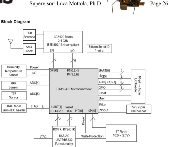
An example of a common sensor node is the Tmote Sky wireless sensor node from MoteIV. Since this thesis report is based on experiments done with the Tmote Sky, focus of sensor node structure will be placed on the devices and sensor included onboard the Tmote Sky board. Pictures of the board, back and front view can be seen in [fig 2.5] and [fig 2.6]. The full block diagram of the Tmote Sky board with its components can be seen in [fig 2.7].
Thesis worker: Erik Öström 2010-05-05 Supervisor: Luca Mottola, Ph.D. Page 25 of 87
Figure 2.5: A Tmote Sky Sensor Node - Front Side [21]
Figure 2.6: A Tmote Sky Sensor Node - Back Side [21]
The core of the Tmote Sky nodes low power consumption is much due to the ultra low power consumption of the MSP430 F1611 microcontroller. The MSP430 is a 16-bit RISC processor from Texas Instruments featuring 10kB RAM, 48kB flash memory and 128 byte information storage. It has an internal digitally controlled oscillator that is capable of operating at 8MHz and has the ability to be recalibrated if needed. The MSP430 also features extremely low active and sleep power consumption and very fast sleep mode transition time. The low power consumption of the MSP430 allows it to operate for years off a pair of AA batteries [21].
Thesis worker: Erik Öström 2010-05-05 Supervisor: Luca Mottola, Ph.D. Page 26 of 87
Figure 2.7: Functional block diagram of the Tmote Sky Sensor Node, its components and buses. [21]
In addition to fast operation the MSP430 has 16 ADC ports, 8 internal and 8 external, which may be used for battery monitoring or internal heat monitoring (through an internal termistor). Also support for communication through SPI, UART interface and digital I/O ports. For wireless communication the Tmote Sky uses the cc2420 radio transceiver.
2.4
Wireless communication in sensor networks
A wireless sensor network is a network that consists of wireless nodes with sensor capabilities. Every node in the network is capable of collecting data from their own sensors, process it and communicate the results wirelessly to other nodes in the network. Common applications for WSNs are in industrial automation, medical monitoring, agriculture, surveillance, asset tracking and home automation. WSNs also have many military applications; they can be an integral part of military command, control, communications, computing, intelligence, surveillance, reconnaissance and targeting [9]. They can also be used for monitoring friendly forces, their equipment and ammunition, targeting and recognizance of enemy forces, detection of biological and chemical attacks and bring valuable assistance to strategic management through battlefield
Thesis worker: Erik Öström 2010-05-05 Supervisor: Luca Mottola, Ph.D. Page 27 of 87
surveillance. WSNs most often communicate using the 802.15.4 communication standard. The IEEE 802.15.4 is one of the most widespread low power communication protocols today. It is specially designed for low power wireless communication and it can operate on three different frequency bands, but only the 2.4 GHz band is accepted worldwide. The 802.15.4 using 2.4 GHz communication operates on the same frequency band as the 802.11b standard (WLAN) and Bluetooth communications. It has 16 non-overlapping channels between frequencies 2405-2480 MHz. Each channel is equidistantly spaced over the spectrum making them spaced 5 MHz apart. The 802.15.4 standard operates by sending 2 MHz chips through direct sequence O-QPSK (Offset Quadrature Phase Shift Keying) modulation. Each chip represents one value bit, where each 32 received chips represents a value between 0-31 which corresponds to a 4-bit symbol. This gives the 802.15.4 standard a physical bandwidth of 250 kbps. IEEE 802.15.4 compliant radio chips, such as cc2420, which is one of the most common 802.15.4 compliant radio chips, feature programmable transmission power and hardware MAC encryption. The IEEE 802.15.4 standard also attaches two extra metadata values to each packet it receives. These are the RSSI (Received Signal Strength Indicator) and LQI (Link Quality Indicator). On the cc2420 however LQI is replaced by the CCI (Chip Correlation Indicator), but since this is closely comparable to LQI which is a more commonly used measurement, the CCI metadata will be referred as LQI for the rest of this thesis report.
RSSI is the measurement of the received signal strength in dB. This tells how strong the signal presence is perceived and thus how likely it is to withstand noise in the area. LQI is a link quality metric defined in the 802.15.4 standard. It gives a value of the current quality for the last received signal, an indication of how pure the received signal is. LQI is calculated by accumulating the magnitude of the error between ideal constellations and the received signal. It then represents this as an estimation of how easily the received signal can be demodulated to the original signal. Both these calculations are done during the first symbols of each received message so both RSSI and LQI is calculated during the first 8 chips after the sync word [21]. The LQI value is represented as a value between 50 and 110, where 110 is the best indication and 50 is the worst. LQI has no real relation to RSSI but the signal quality is often linked to signal strength. This can easiest be explained by the fact that a strong signal is less likely to be affected by noise and is therefore perceived as cleaner by the receiver. Even though these values cannot be predicted for a specific case, some general behavior can be proposed. RSSI is a good indicator of signal quality when it is above the sensitivity threshold of the 802.15.4 compliant radio, in the
Thesis worker: Erik Öström 2010-05-05 Supervisor: Luca Mottola, Ph.D. Page 28 of 87
case of the cc2420; this value is above -87 dB [13]. The RSSI value does however not have a good correlation with packet reception rate at the edge of the sensitivity spectrum due to noise but has a good stable consistency over time. LQI average on the other hand has a good correlation with packet reception rate when it is averaged over a large enough number of packets, at least 120 packets [13], but has much variation over time. Researchers in [10] however show a method of estimating good quality links, using the LQI average, over much smaller number packets. This is very useful in advanced dynamic routing protocols where fast link evaluation can help optimize the lifetime and throughput of the entire WSN.
2.5
Directional and Smart Antennas in WSNs
One of the biggest technical challenges of WSNs today is managing energy consumption without compromising other aspects such as range, throughput or general functionality. As researchers in [11] show, the radio communication is one of the most energy consuming activities in WSNs, this makes efficient routing protocols very important. The main concept behind research that proposes new routing algorithms in low power networks is to optimize the power usage more efficiently; to obtain more throughput and longer lifetime of the entire network. This involves important aspects such as transitions between different modes like transmitting, idle, power down and sleep modes [19, 8]. But as more and more research shows, one of the most important aspects of efficient routing protocols is to take advantage of modern antenna technology such as the benefits of directionality.
The use of directional or smart antennas can help optimize a WSN by increasing the range of every node, thus giving options for spatial reuse and lowering power consumption of the entire network [4]. They can as researchers in [5] show; also minimize interference coming from other wireless devices in the area, devices which operate on the same frequencies as the WSN like wireless computer networks and Blue tooth devices. These properties are what make the usage of directional and smart antennas in WSN become very appealing.
Substantial research shows the potentials for increasing overall WSN efficiency through the usage of directional antenna compliant protocols [2, 3, 4, 6, 7, 14, and 15]. Researchers in [2] describe some significant issues in contention-based MAC (Media Access Control) protocols for directional antennas and present a MAC design to overcome the discussed difficulties. The work in [3] focuses on the usage of directional antennas in mobile ad hoc networks, or MANETs, networks that configure themselves autonomously without relying on underlying
Thesis worker: Erik Öström 2010-05-05 Supervisor: Luca Mottola, Ph.D. Page 29 of 87
infrastructure such as a base station. In their work they present a new carrier sense mechanism called DVCS (Direct Virtual Carrier Sensing) for usage in those types of networks. Other work in [7] provides a directional antenna protocol called IDDA (Interest Dissemination with Directional Antennas) which is shown to improve efficiency and network lifetime in WSN that have mobile data sinks. The protocol in [14] also shows extended lifetime of the WSN by use of their scheme DAaS (Directional Antenna at Sink). DAaS is a sink beam pattern schedule, that also minimize bottlenecks (nodes that pass on a lot of traffic) in the network, this is done by involving more nodes as sink connected nodes (nodes within reach of the sink) by using the wider reach of the directional antenna. Researchers in [15] however, focus only on WSNs where all nodes are equipped with directional antennas. They have come up with the DtD (Directional-to-Directional) MAC protocol which is designed for running in ad hoc networks.
Figure 2.8: Four element Switched Beam Antenna [1]
Thesis worker: Erik Öström 2010-05-05 Supervisor: Luca Mottola, Ph.D. Page 30 of 87
Even though many papers talk about the advantages of directional antennas and their usage in WSNs, few actual experimental researches have been performed with actual directional antennas and even less using smart antennas. There are a few papers that talk about using similar antenna types to smart antennas, antennas that consist of different directional antenna elements put together. Two of which are the SBA (Switched Beam Antenna) and the FBPA (Four-Beam Patch Antenna). These types can be seen in [fig 2.8], which shows a MaxBeam switched beam antenna and in [fig 2.9], which shows the FBPA used in [5]. Researchers in [1] and [6] propose the use of the SBA (Switched Beam Antenna) and show simulated data results of that. In [6] the impacts of using the SBA with the S-MAC protocol in a WSN are shown. The results show reduction of interference, transmission delay and flooding, which leads to increased throughput and lifetime of the network. Researchers in [1] propose the introduction of an SBA into a sensor network running a synchronized contention-based sleep/awake MAC protocol called Dir-MAC, which is specially modified for working with directional antennas. Simulations in the paper show significant improvements of throughput of up to 4 times and a reduction of power consumption of 50%.
The work in [5] is one of the few that show actual experiments using an early prototype smart antenna. They consider the design of the FBPA directional antenna seen in [fig 2.9]. The FBPA in [5] is designed to work in the 2.4 GHz ISM band running on the IEEE 802.15.4 standard. The FBPA antenna has the ability to change direction of the beam from any of the four sides of the cube through the use of two I/O lines, which makes it a limited but still smart antenna. Unfortunately the actual antenna size is too big and bulky to be easily applicable in a real WSN. The researchers perform experiments using the antenna in a WSN consisting of COTS motes. The results of which show an increase of signal reach from 140m to 350m in outdoor experiments and some indoor experiments show a suppression of interference due to multi-path fading by reducing the signal variability of more than 70%. They also show suppression of interference coming from 802.11g devices.
Another relevant work to this thesis is the work in [12] where the researchers have done studies on the on-board micro strip antenna of the Tmote Sky sensor node. This work is relevant since they performed somewhat similar measurements as the ones in this thesis and their results and discussion provides supporting arguments to results and observations presented in this thesis report. What can be noticed from doing a background research in the area is what was also stated above, that next to no real experiments using real smart antennas. All
Thesis worker: Erik Öström 2010-05-05 Supervisor: Luca Mottola, Ph.D. Page 31 of 87
research found except the work in [5], are either on directional antennas or discussions and simulations on the usage of smart antennas. No work has been found that has produced a real functional smart antenna prototype that is small enough to be directly applicable in a real world application such as a wireless sensor network. This thesis sets apart from other existing works in the way that it produces and presents measurements from live experiments using a real smart antenna. It involves both design and building a real functional smart antenna that is small, consumes almost no power and is very cheap to produce.
Thesis worker: Erik Öström 2010-05-05 Supervisor: Luca Mottola, Ph.D. Page 32 of 87
3 Hardware/Software design and implementation
3.1
Hardware design
The platform chosen for this project was the Tmote Sky sensor node. This was chosen because the Tmote Sky is one of the most commonly used sensor nodes in WSNs. It is a widely used sensor node that is easy to use, can easily be reconfigured for an external SMA connected antenna and was available at SICS at the time of this thesis. These experiments could however have been performed using numerous other platforms as well.
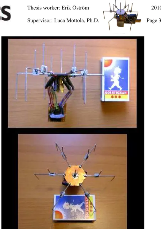
Three antenna types were used in this thesis. The Tmote Sky onboard micro strip antenna was used for some preliminary testing and some reference experiments. SMA connected rod antennas were used on all receiving nodes during all the experiments performed in this thesis. The special antenna of this thesis is the SPIDA smart antenna, a controllable version of the directional SPIDA designed in [16]. The previous directional SPIDA was redesigned as a part of this thesis to produce the controllable SPIDA smart antenna version. This version was built to fulfill one of the main goals of this thesis; the final SPIDA smart antenna built can be seen in [fig 3.1].
The SPIDA antenna is an ESPE (Electronically Switched Parasitic Element) type antenna that is designed for the 2.4 GHz ISM band. It consists of a central monopole surrounded by monopole-like elements which are spaced approximately λ/4 apart. The theory of the antenna function is that it works by letting every electronically controlled parasitic element be either isolated or connected to ground. When a monopole-like element is connected it works like a reflector, reflecting the beam, and when it is isolated it works like a director, directing the beam in that direction. Thoughts and purpose for the development of the SPIDA antenna along with building instructions for the first directional version can be found in [16]. The main purpose for the SPIDA design was centered on using it for localization and in advanced routing algorithms, by using its ability to tell the angle of arrival of incoming packets. One of the other benefits of the SPIDA mentioned in [16] is the low cost of the entire antenna; the cost mainly being dominated by the cost of the SMA connector, which could be exchanged for any connector type of choice. The research in [16] also presents some early measurements done on the SPIDA antenna along with simulated data charts and a 3D signal spectrum produced by the NEC2 simulator. These charts and pictures can be found in the discussion in chapter 5 along with the real data charts produced in this thesis work.
Thesis worker: Erik Öström 2010-05-05 Supervisor: Luca Mottola, Ph.D. Page 33 of 87
Figure 3.1: SPIDA Smart Antenna
3.2
Hardware construction
The dimensions blueprint of the SPIDA [fig 3.2] is the same as of the first directional prototype in [16], except for a modification on the hardwired leg; this is the leg that was glued onto a piece of triangular plastic to simulate active communication for that leg [16]. The dimensional design of the SPIDA was engineered and optimized through NEC simulations by a researcher at SICS.
Thesis worker: Erik Öström 2010-05-05 Supervisor: Luca Mottola, Ph.D. Page 34 of 87
Figure 3.2: SPIDA dimensions blueprint, top view and side view [16]
Figure 3.3: SPIDA base-board bottom-side layout with etching pattern
The electronics schematics for the controllable SPIDA, was completely designed in this thesis. The final schematics can be seen in [fig 3.4] and was used for the final version controllable SPIDA (Smart Antenna). The final schematics design was designed while taking into account the major issues of functionality and having as much interference and noise suppression as possible, but also with some secondary issues in mind like size, cost and building simplicity. The filters and components used where selected after discussing suggestions with antenna designers.
Thesis worker: Erik Öström 2010-05-05 Supervisor: Luca Mottola, Ph.D. Page 35 of 87
Figure 3.4: SPIDA electronics schematics simplified to only one direction
The schematics contain two LC filters for every I/O line going between the antenna and the microcontroller, these filters decouples spikes and stabilizes the signal regarding RF-and magnetic interference. These filters are not necessarily needed but they were put there for a pre-empt purpose, also some future plans involve changing the type of switches used from digital to analog and those signals require heavier filtering. The values of the filter components are not completely optimized but they are considered to have a good noise reducing effect for both outside-and internal noise coming from the Tmote, at the selected values. The Vcc power line was also equipped with the same filtering as the I/O lines and also some additional decoupling capacitors placed evenly around the base-board for a more even performance. The base-board etching pattern was designed to allow an effective ground plane and simple effective soldering. The base-board etching pattern used can be seen in [fig 3.3]. The switching ICs selected for the smart antenna design was ADG902, they are high frequency SPST switches from Analog Devices. These were selected for their size, cost and high frequency bandwidth and were the suggested choice by the designer of the directional SPIDA antenna. The ADG902 have digital on off switching through a single I/O line and have a frequency bandwidth of 4.5 GHz. They do however at the 2.4 GHz frequency range, work near the edge of their capacity in some aspects, so there might be alternative components that show even better
Thesis worker: Erik Öström 2010-05-05 Supervisor: Luca Mottola, Ph.D. Page 36 of 87
performance at this specific frequency range. To connect the antenna to the Tmote Sky board a 10-pin connector was used. The 10-pin connector and the first seven LC filters was soldered onto a Vero board, this board is referred to as the adapter board and a picture of the final soldering pattern for this adapter board can be seen in [fig 3.5].
Figure 3.5: Adapter board side view and soldering pattern
The SPIDA base-plane was built by first milling out the hexagonal base-plane from double sided copper Vero board and drilling the center hole. This produces a very exact measured base-board which would otherwise give the antenna an uneven effect. The separation etching pattern in [fig 3.3], was then etched onto the board surface of the base-board making it into two separate planes and six round islands, as seen in the top right corner of [fig 3.6]. The purpose of this was to make a common ground plane in the middle with a surrounding Vcc plane and local connections for each I/O line coming from the microcontroller. This ground plane also benefits the antenna with a more even performance and the islands provides stronger soldering points and allows surface mounted decoupling. The decoupling capacitors were then soldered onto the board, one for each island and seven for the Vcc plane. These were placed at symmetric distances around the board to provide an even performance for all directions, as seen in the middle picture in [fig 3.6]. Finally each island was connected to an inductor by a piece of wire, this to reduce stiffness in the connections, seen in right most pictures of [fig 3.6]. These inductors are then acting as soldering points for the cables going to the adapter board.
Thesis worker: Erik Öström 2010-05-05 Supervisor: Luca Mottola, Ph.D. Page 37 of 87
Figure 3.6: SPIDA base-plane with decoupling capacitors and inductors
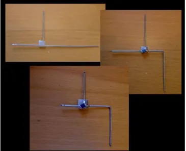
The legs of the SPIDA were built by gluing two pieces of tinned copper-wire in a T-like connection without having them touch each other. This produces a stronger stiffness and easier mounting of the switch IC. An SPST switch IC was then soldered onto of each T-connection, connecting the wires through it. The wires were then bent and cut to size with careful measuring. All three steps are illustrated in [fig 3.7].
Thesis worker: Erik Öström 2010-05-05 Supervisor: Luca Mottola, Ph.D. Page 38 of 87
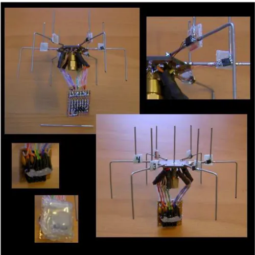
The legs were then soldered onto the topside of the SPIDA base-plane and the SMA-connector was attached in the center hole. The base-plane inductors were connected to the adapter board by twisted pair wire, running each I/O line together with a ground wire for maximum interference protection. A thin two lead wire were used to connect each switch IC to the Vcc plane and each respective island (top right picture of [fig 3.8]). These provide the Vcc power and I/O signal for each respective IC. The wire were kept as short as possible and placed running underneath each leg for minimum antenna field disturbance. Finally the adaptor board was hot glued for short circuit protection, all antenna directions were numbered (clockwise from 1 to 6) and the center pole was put in place. The final result is shown in the lower right picture of [fig 3.8].
Figure 3.8: Complete SPIDA Smart Antenna
3.3
Driver design & implementation
The operating system running on the nodes during the experiments is the Contiki operating system. Contiki is an interrupt based operating system for wireless nodes developed at SICS. The language in which the experiment code
Thesis worker: Erik Öström 2010-05-05 Supervisor: Luca Mottola, Ph.D. Page 39 of 87
and drivers were written in is C with some Contiki specific structure and function calls. The drivers work by defining six of the MSP430s externally connected pins, as I/O pins, through the Contiki OS hardware configuration file (hwconf.h). These six pins are located on the Tmote Sky U2 connector which can be found through the Tmote Sky datasheet [21], or seen in figure 2.5. The pins used for the six I/O lines are pins 2, 3, 4, 5, 7 and 10, which pin corresponds to what direction can be found by editing the driver c-file. The drivers consist of two files, spida_sky.h and spida_sky.c. The c-file contains five functions for operating the SPIDA smart antenna. First function is a void function which initializes the drivers by configuring the associated pins. Second and third functions are for activating or deactivating the requested direction number. The final two functions offers a faster way to change all direction by automatically configure all six pins according to a requested statement. The spida_set_dir function configures communication over one specific direction. The function takes an input from 0 to 7, were “1” to “6” is the directions 1 to 6, “0” is no direction and “7” is all directions (omni-directional-mode). The final function spida_dir, configures all direction simultaneously with full freedom of manipulation. It takes input values for all directions and turns on all directions that are set to non-zero values, and turns off all directions set to zero. This function can easily be adjusted for future analog control for each direction switch. These five driver functions together offer the user easy operation and full control over the SPIDA directions with a minimum number of code lines. The complete set of functions and some sample code can be seen in [fig 3.9] and [fig 3.10].
Function Input range Description
spida_init(void) - Initializes I/O pins
spida_activate_direction(int direction)
1-6 Sets the corresponding I/O pin high
spida_deactivate_direction(int direction)
1-6 Sets the corresponding I/O pin low
spida_set_dir(int direction) 0-7 Configures all I/O pins for communication over the requested direction
Thesis worker: Erik Öström 2010-05-05 Supervisor: Luca Mottola, Ph.D. Page 40 of 87
spida_dir(int direction1, int direction2, int direction3, int direction4, int direction5, int direction6)
0-1 (Currently only uses digital switching)
Configure all I/O pins according to all direction requests
Figure 3.9: SPIDA driver functions
Code sample:
#include "spida_sky.h" //Include drivers Main(void) {
spida_init(); //Define I/O pins, turn off all directions while(1) {
spida_set_dir(7); //Turn on all directions, “omni directional mode” …
spida_dir(0,1,0,0,0,0); //Turn off all directions, turn on direction 2, “directional mode (2)”
spida_dir(0,0,0,1,0,1); //Turn off all directions, turn on directions 4 and 6, “multi-directional mode (4,6)”
spida_activate_direction(3); //Turn on direction 3, “multi-directional mode (3,4,6)”
…
spida_deactivate_direction(4); //Turn off direction 4, “multi-directional mode (3,6)”
…
spida_set_dir(0); //Turn off all directions, “blocked mode” }
} // End Main
Thesis worker: Erik Öström 2010-05-05 Supervisor: Luca Mottola, Ph.D. Page 41 of 87
4 Experiment goals & setup
The experiments were designed and executed in consideration of these four aspects:
• Verify general SPIDA behavior
• Evaluating the signal reach of the SPIDA smart antenna • Study the SPIDA smart antenna signal pattern
• Verify the directional behavior of the SPIDA smart antenna
To start off measuring and evaluating the SPIDA antenna a simpler non controllable version was first created. This version was a copy of the directional SPIDA described in [16]. It has the same basic structure as the controllable SPIDA but without any electronics. This simpler version only has one of its six directions active, the active direction pin is glued onto a piece of Plexiglas while the other five direction pins are hardwired to ground, same concept as in [16]. This directional SPIDA version was used for the first number of experiments to get some evaluation data for the SPIDA antennas behavior without the influence of the controlling electronics. This version of the SPIDA is referred to as the first version or non-controllable version SPIDA, whilst the other version with all the electronics is referred to as the controllable version SPIDA. The controllable version in turn was built with two variations of the same physical one. This because a flaw was found in the first controllable variation and some changes had to be done to it. These two are referred to as the first variation and second variation controllable SPIDA, the second controllable SPIDA variation is also referred to as the final controllable version and is only used in the final experiment (CDT3).
To cover the aspects mentioned above and achieve the results needed for the experimental part of this thesis, some different experiments were designed. The first experiment needed to give an estimation of the signal reach of the SPIDA antenna. This distance was needed both for comparison to other antennas and to decide the most practical distance to use when setting up the rest of the experiments that were performed. Secondary experiments had their main focus on evaluating the antenna signal pattern and most of them were designed depending on the results and progress of the preceding one. Their individual goals and designs are explained in turn during this chapter. Two test programs
Thesis worker: Erik Öström 2010-05-05 Supervisor: Luca Mottola, Ph.D. Page 42 of 87
were written for the experiments. The first one showed PRR (Packet Reception Rate), RSSI, LQI, Ambient Humidity, Temperature and Noice at the receiving node. The other program complemented this by showing PRR and RSSI received from each direction separately, this program made the evaluation of the controllable SPIDA much easier.
Since on-board battery power on the nodes alters over time, all nodes in the experiments were powered through a stable power source. The only exception from this was the indoor experiments performed in experiment CDT2 and CDT3, where fresh batteries were used on all receiver nodes instead. This was done for time efficiency and allowed faster and simpler experimentation. This was considered ok because of the short experimentation times and the lesser importance of these indoor measurements, which were to be reconfirmed outdoor as the rest of the experiments. The power source used for the outdoor experiments consisted of an 8-port USB hub, powered by a regulated stand alone power transformer.
All the experiments were performed using one node with the SPIDA antenna mounted and the rest of the nodes used an externally connected Omni-directional rod antenna. The SPIDA smart antenna node was always only transmitting and the rest of the nodes called probe nodes were always only receiving. This setup was chosen since it was the best way to perform the experiments and works since the signal patterns for transmission and reception for the SPIDA are identical.
4.1
Location
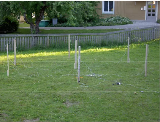
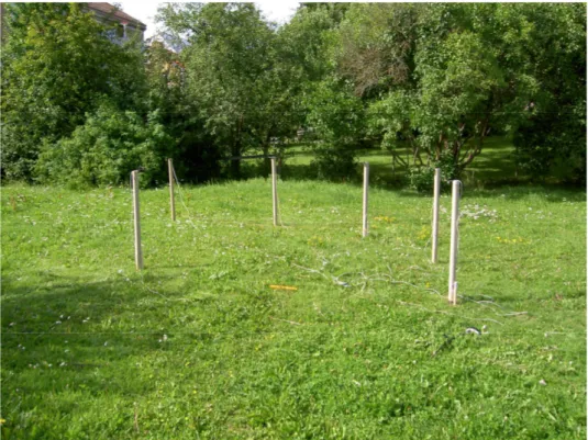
The testing environments ideal condition should be as open (absence of obstacles) and noise free as possible, this is desired to minimize outside interference and tainted results due to bouncing signals. Preliminary measurements indoors showed an unforeseen long signal reach, this lead to the possibility of unwanted signal bouncing and thus tainted results. So instead an outdoor open grass plain was chosen for the experimental phase of this thesis. The outdoor lot can be seen in [fig 4.1].
The preliminary results did showed that the most practical transmission power to be used for these experiments was the lowest power setting of the cc2420 possible, transmission (TX) power 1. This transmission power corresponds to approximately -30 dB in signal strength and consumes about 8 mA [22]. Since the theoretical range of the smart antenna should outperform the onboard micro strip antenna, which is specified to be at least 125m at full power [21],
Thesis worker: Erik Öström 2010-05-05 Supervisor: Luca Mottola, Ph.D. Page 43 of 87
measuring packet loss within 10m from the transmitter at full power would not provide meaningful results for this experiments purpose. This since there should theoretically be no packets lost because of weak signal strength within such a short range. Therefore all the decisive experiments were performed with TX power setting 1. Some secondary experiments were however sometimes performed at TX power 2 or 3 to confirm some obtained results. These secondary experiments are explained in the discussion chapter and all measurements are performed at TX power 1 unless otherwise specified.
Figure 4.1: Grass lot where the experiments were performed
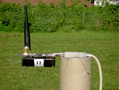
For all the experiments the nodes were mounted on 106.7 cm long cardboard pillars that are secured in the ground by wooden poles. These poles also served as an extra height adjuster where the ground was slightly lower. The smart antenna node was always mounted vertical to the ground at the top of the cardboard pillar [fig 4.2], thus putting the smart antenna horizontal to the ground plane. The Omni-directional-and micro strip-antenna nodes were instead always mounted horizontally to the ground putting their antennas also horizontal to the ground plane [fig 4.3]. Mounting of the nodes and placement of the cardboard pillars where enforced by a water level measurement tool, laser pointer, string and measuring tape.
Thesis worker: Erik Öström 2010-05-05 Supervisor: Luca Mottola, Ph.D. Page 44 of 87
Figure 4.2: Smart antenna node mounted vertically on cardboard pillar
Figure 4.3: Omni-directional antenna node mounted horizontally on cardboard pillar
4.2
General settings
In the experiments that follow, some experiment parameters are identical in all the experiments. This due to all experiments having some basic properties in common, like recommended height above ground and they should also have comparable node orientation. Since the experiments also have similar nature in measurement methods and goals, the input and output metrics are also identical for all experiments. These parameters can be best understood after reading the experiment layouts, but will be placed here for common reference.