This is the published version of a paper published in International Journal of Distributed Sensor
Networks.
Citation for the original published paper (version of record):
Yu, K., Pang, Z., Gidlund, M., Åkerberg, J., Björkman, M. (2014)
REALFLOW: Reliable Real-Time Flooding-Based Routing Protocol for Industrial Wireless Sensor
Networks.
International Journal of Distributed Sensor Networks, : art. nbr: 936379
Access to the published version may require subscription.
N.B. When citing this work, cite the original published paper.
Permanent link to this version:
Research Article
REALFLOW: Reliable Real-Time Flooding-Based Routing
Protocol for Industrial Wireless Sensor Networks
Kan Yu,
1Zhibo Pang,
2Mikael Gidlund,
2Johan Åkerberg,
2and Mats Björkman
11School of Innovation, Design and Engineering, M¨alardalen University, P.O. Box 883, 72123 V¨aster˚as, Sweden 2ABB AB, Corporate Research, Tegn´er, 72178 V¨aster˚as, Sweden
Correspondence should be addressed to Kan Yu; kan.yu@mdh.se Received 12 December 2013; Accepted 23 May 2014; Published 15 July 2014 Academic Editor: Shancang Li
Copyright © 2014 Kan Yu et al. This is an open access article distributed under the Creative Commons Attribution License, which permits unrestricted use, distribution, and reproduction in any medium, provided the original work is properly cited.
Wireless technologies have been increasingly applied in industrial automation systems due to flexible installation, mobility, and cost reduction. Unlike traditional wireless sensor networks (WSNs), industrial wireless sensor networks (IWSNs), when expanding from wireless monitoring to wireless control, have more stringent requirements on reliability, real-time performance, and robustness in a number of industrial applications. Successive transmission failures or deadline misses in these applications may severely degrade the control quality and result in serious economic losses and safety problems. Therefore, when deploying IWSNs in harsh industrial environments, to achieve reliable and deterministic end-to-end transmissions is critically important. In this paper, we explain the primary challenges of designing appropriate routing protocols and present a reliable real-time flooding-based routing protocol for IWSNs (REALFLOW). Instead of traditional routing tables, related node lists are generated in a simple distributed manner, serving for packet forwarding. A controlled flooding mechanism is applied to improve both reliability and real-time performance. A seamless transition in the event of topology change can be achieved by REALFLOW. Performance evaluations via simulations verify that significant improvements of reliability, real-time performance, and network recovery time can be achieved by REALFLOW, compared with traditional routing protocols.
1. Introduction
Nowadays, wireless sensor networks (WSNs) have been exhibiting their attractive advantages over traditional wired counterpart for industrial automation systems, such as the avoidance of cabling and flexible installation. Industrial wireless sensor networks (IWSNs) can serve a number of purposes, such as monitoring and control. Currently, wireless monitoring via IWSNs for industrial applications has been widely applied [1]. Nevertheless, wireless control, as an essential part of automation, is still lacking support in IWSNs [2]. Compared with wireless monitoring, data transmissions for wireless control in many industrial applications should be sufficiently reliable [3] and deterministic with the latency of the order of seconds, or even milliseconds [2]. Transmission failures or deadline misses may result in disturbances to the process, degradation of the overall control performance, and even more serious economic losses or human safety problems. Once both wireless monitoring and control are
fully supported, the booming development of IWSN appli-cations can be expected. Besides high reliability and real-time performance, low energy consumption is also an impor-tant issue [4–6]. However, compared with the former two requirements, reducing energy consumption should not be prioritized as high as reliable and deterministic transmission for different industrial applications.
Compared with environments for traditional WSNs, industrial environments for IWSNs are harsher and more dynamic due to a great number of metallic surfaces, extreme temperature, high vibrations, and mobility of nodes and other objects [7]. Measurements from [8,9] have shown that deep fading and shadowing in industrial environments may result in extremely low received signal strength indicator (RSSI) values with high variances or even packet losses. Moreover, authors in [7, 10] pointed out coexisting communication systems in the same frequency band as another major source of disturbances to wireless industrial applications. Hence, the
Volume 2014, Article ID 936379, 17 pages http://dx.doi.org/10.1155/2014/936379
major challenge is to achieve reliable and deterministic end-to-end transmissions in industrial environments by using IWSNs. Currently, several standards have been published for process measurements and control applications. Among them, Zigbee [11] is shown to be unsuitable for industrial automation because there are no frequency diversity, no path diversity, and the MAC unreliability problem [12, 13]. WirelessHART [14] and ISA 100.11a [15] are another two standards designed for process automation (PA). Although some successful deployment instances exhibit the confidence on these standards, there is still a long way to go to fulfill the reliability and real-time performance requirements for most of industrial applications [2]. The improvement can be achieved on different layers. On existing devices, limited efforts can be taken on the physical layer due to restrictions imposed by hardware and/or software limitations. On the MAC layer, a number of techniques, such as channel hopping and black listing, are used to improve reliability, but in harsh industrial environments, transmission failures still occur quite often. Although automatic repeat-request (ARQ) is applied in most of the standards, and it is a straightforward method to increase reliability, the real-time performance is degraded due to retransmissions. The previous empirical results [16] exhibit serious consequences such as network congestions, caused by excessive unexpected retransmissions. On the network layer, the routing protocol plays an extremely important role in achieving high reliability and low latency [1], but the current standards fail to provide sufficient guid-ance on how to guarantee reliable and real-time transmission by using appropriate routing protocols. Although a number of research efforts have been taken to design a reliable real-time routing protocol for IWSNs [17–22], there is still no sufficient evidence to show that the problem has been fully solved.
There are several challenges to design an appropriate routing protocol for IWSNs. Firstly, if high reliability cannot be achieved by the lower layers, multipath diversity can be applied by routing protocols on the network layer to increase reliability. Retransmission is an effective method to increase reliability, but the transmission delay is also prolonged. For many industrial applications where hard deadline is strictly required, outdated packets are of limited use for their destinations. Therefore, the second challenge is that real-time performance should be provided by a routing protocol. Thirdly, routing protocols should be tolerant of sudden topology changes, such as link failures and node halting. Once the topology changes, the routing protocol should provide an alternative path as soon as possible; otherwise data transmissions may be terminated during the path recalculation period. The last challenge is that the workload of nodes should be also considered. Different from traditional WSNs, the network structure of an IWSN is typically centralized, since operators in the central control room must have the knowledge of the status of the whole network. Thus, the gateway or network manager, as the central device, is involved in most of network activities. The gateway or network manager should not spend too long time on calculating routing information, since partial communication in the network may be halted during the calculation period due to the outdated routing information.
Therefore, when designing a routing protocol for IWSNs, these challenges should be addressed.
In this paper, we propose a reliable real-time flooding-based routing protocol for IWSNs (REALFLOW) to address all challenges mentioned above. REALFLOW consists of a routing establishing and maintenance part and packet forwarding part. The gateway periodically broadcasts discov-ering messages, named as list-updated messages, to discover the current network topology. After list-updated messages are received, all nodes should send corresponding responses, named as updated messages, back to the gateway. The list-response message transmission stage has two purposes: one is that it helps the gateway obtain the current network topology information; the other is that related node lists are generated in all nodes based on receiving list-response messages from other nodes. For both uplink and downlink transmissions, packets are forwarded according to the related node lists in all intermediate nodes. In order to improve reliability, REALFLOW is based on the controlled flooding mechanism to provide multipath diversity. The real-time performance is also considered, so outdated packets are automatically discarded in intermediate nodes. Due to redundant paths and flooding mechanism, REALFLOW can be tolerant of parts of network topology changes. Since related node lists are distributively generated in all nodes, the workloads of the gateway are greatly reduced.
Due to flooding mechanism, more resources may be required than traditional routing protocols in WSNs. How-ever, as we emphasized previously, in many industrial appli-cations, especially those from industrial automation systems, reliability and real-time performance should be prioritized for IWSNs, rather than energy consumption. Moreover, it is proven that energy consumed by local processing, such as sensoring, dominates the overall energy consumption [23]. Although additional communication is introduced in the network due to flooding, the increment of energy consump-tion caused by addiconsump-tional communicaconsump-tion is not obvious. Therefore, our work bridges the gap of current research works to provide reliable and real-time end-to-end transmissions in IWSNs.
The rest of this paper is organized as follows:Section 2 presents the previous work on routing protocols in WSNs. In Section 3, we briefly describe the current IWSN architecture as background knowledge. InSection 4, we outline the pro-posed routing protocol REALFLOW. The simulation settings and scenarios are described in Section 5, followed by the simulation result analysis inSection 6. Finally, we conclude the paper inSection 7.
2. Related Work
Designing reliable routing protocols in WSNs, as one of the most challenging research topics, has attracted a great number of research interests. Traditional routing protocols, such as dynamic source routing protocol (DSR) [24] and ad hoc on-demand distance vector protocol (AODV) [25], have been successfully applied in traditional WSNs, such as
Zigbee networks. For this set of routing protocols, route dis-covery messages are broadcast to discover all available paths. In order to maintain the updated routing information, all nodes have to frequently exchange information for being aware of channel status. If any link is broken or node halts, all corresponding nodes have to recalculate the routing information and try to establish another new path. During this period, parts of the network may not work properly, which makes the network suffer from higher latency and lower reliability. Several extensions of traditional routing protocols were also proposed, for instance, the ad hoc on-demand multipath distance vector protocol (AOMDV) [26], the ad hoc on-demand distance vector multipath routing protocol (AODVM) [27], and split multipath routing (SMR) [28]. These extensions intend to improve reliability by identifying multiple nodes or edge-disjoint paths. However, primary drawbacks, such as excessive control messages and unpredictable network recovery time, still exist. Besides these extensions, multipath routing protocols have been extensively studied in other research works aiming for high reliability [17–20]. Authors in [19] split each packet into several subpackets by using erasure codes and send them instead of the whole packet. This scheme might be effective in traditional WSNs, but in IWSNs there exist very short packets with the strict deadline; this scheme may be hardly used in IWSNs, since the real-time performance is not fully considered. A reliable information forwarding using multiple paths (ReInForM) protocol proposed in [20] can achieve controlled reliability by sending redundant copies of a packet along multiple paths. However, this protocol can only be used under a number of assumptions. For instance, every node has knowledge of the local channel error and is able to compute the information content and importance of sensed events, which can hardly be obtained in many practical scenarios.
Unlike traditional routing protocols and all their exten-sions, flooding is an effective approach to increase reliability by multipath diversity. However, previous flooding-based routing protocols fail to satisfy industrial requirements. Authors in [29] try to avoid the drawbacks of flooding by randomizing the selection of retransmitters. Their approach may hardly be used for a centralized TDMA-based IWSN, since it may bring difficulties for scheduling. A random rout-ing strategy based on floodrout-ing proposed in [30] aims for low energy consumption. However, according to the evaluation results, even higher end-to-end transmission latency may be introduced, although lower energy consumption is provided by their proposed routing algorithm.
Except for reliable routing protocols in traditional WSNs, there also exist a number of newly proposed routing protocols to address the challenges from IWSNs. MERLIN protocol proposed in [21] utilizes multicast for both uplink and downlink transmissions to improve low latency and energy consumption, but high reliability is not the main scope of this protocol. Authors in [31] proposed EARQ, an energy aware routing protocol also for reliable and real-time com-munications in IWSNs. Next hop selections are based on the estimations of energy consumption, reliability, and deadlines. However, according to their evaluation settings, this protocol may be more suitable for WLAN or Zigbee networks, not
centralized TDMA IWSNs. Both authors in [32,33] proposed a two-hop information-based routing protocol, aiming for enhancing real-time performance with energy efficiency. The routing decision in [32] is based on the two-hop velocity integrated with energy balancing mechanism, whereas the routing decision in [33] is based on the number of hops from source to gateway and two-hop information. However, relia-bility is not fully considered in these two protocols. Authors from [22] also proposed an entire reliable graph routing scheme for broadcast, uplink, and downlink transmissions in IWSNs with promising evaluation results. One drawback of their routing protocol is the too high workload of the gateway or the network manager to calculate all routing graphs [34].
It is notable that energy efficiency and low power consumption have been stressed by a number of previous research works. However, for many time-critical industrial applications, the high reliability and real-time performance are prior to all other requirements. If there are many packet losses or packets cannot arrive at their destinations before deadlines, optimizing energy efficiency and reducing power consumption become meaningless to the whole system. Reliability, availability, and usability of IWSNs should take top priority for those industrial applications. Therefore, different from previous research works, we mainly focus on improving reliability and real-time performance for IWSNs.
3. Industrial Wireless Sensor
Network Architecture
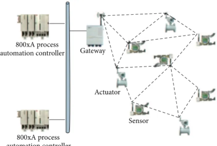
Unlike traditional WSNs, the network structure of an IWSN is generally centralized. Operators in the central control room should have the knowledge of the status of the whole network. A comprehensive IWSN usually contains a number of components, such as network manager, access point, security manager, and field devices. However, the scope of this work is to design routing protocol for reliable and real-time transmissions in IWSNs, so simplified components are considered in this work.Figure 1shows a typical topology of an IWSN considered in this work. Three basic device types are involved in the formation of an IWSN.
(i) Gateway: it is responsible for managing the whole network, including identifying routing, distributing resources, and scheduling decision making. It also connects the control system to field devices.
(ii) Sensor nodes: as one type of field devices, the respon-sibility of a sensor node is to collect all kinds of measurement data and upload to the gateway. (iii) Actuator nodes: as another type of field devices, an
actuator node performs basic functions of actuating after receiving data or commands from the gateway. As shown in Figure 1, in an industrial process control system, a programmable logic controller (PLC) connected to a gateway periodically acquires measurement data from sensor nodes at a certain refresh rate. After executing the control applications, the PLC periodically sends the output values to actuator nodes for actuating. Usually sensor and actuator nodes are deployed in a scattered manner in a
automation controller Gateway Actuator Sensor 800xA process automation controller 800xA process
Figure 1: A typical topology of an IWSN.
large area. According to different wireless channel conditions, uplink and downlink communication may involve one hop or multihop packet transmissions. In order to provide reliable and real-time communication for industrial applications, an appropriate routing protocol serving packet forwarding plays an extremely important role in finding available transmission paths. We should also notice that in many industrial appli-cations the data transmission period is extremely short, for example, 250 ms or 500 ms [2]. Due to the schedulability of transmission timing slots, the network size and node hop numbers are severely limited. Therefore, in many industrial applications an IWSN containing hundreds of nodes and a node with many hops away from the gateway can hardly be seen in those industrial applications.
4. Proposed Reliable Real-Time
Flooding-Based Routing Protocol
To achieve higher reliability, flooding method is used in our proposed routing protocol to introduce multipath diversity. However, the inherent drawback of uncontrolled flooding is that the network resources will be rapidly exhausted. Thus, our proposed routing protocol is based on a controlled flooding mechanism in which flooding behaviors are severely restricted within a certain range, so the usage of network resources can be much more efficient. To assist packets in arriving at their destinations, different routing protocols apply different mechanisms. For instance, routing tables are commonly used in a great number of traditional routing protocols, whereas a graph ID embedded in a message is used by graph routing protocols for forwarding messages in the standard WirelessHART. As we mentioned previously, to gen-erate all routing or graph information at the gateway or net-work manager may require extremely long computation time and lead to overwhelming workload of these devices [34]. Additionally, once the network topology changes, routing tables and graphs need to be recalculated again. During the calculation and recalculation period, partial communication in the network may be terminated due to the outdated routing
information. To avoid this problem, we apply a different mechanism and introduce new routing parameters.
In this section, we present the details of REALFLOW. We first introduce the definitions and notations for our proposed protocol. Then we describe the route establishing and mainte-nance method and packet forwarding method inSection 4.2 andSection 4.3, respectively, followed by an example of our proposed scheme for comprehensive understanding. Finally, a theoretical analysis is given inSection 4.5.
4.1. Definitions and Notations. Provided an IWSAN consists
of𝑚 nodes (sensors and actuators), the node set N is written asN = {𝑁1, 𝑁2, . . . , 𝑁𝑚}. In order to control the flooding behavior efficiently, we introduce a new concept, called
relevant, in our proposed routing protocol. This concept is
defined as below.
Definition 1. If the node𝑁𝑖 (1 ≤ 𝑖 ≤ 𝑚) in the network is
involved in forwarding packets transmitted between the node 𝑁𝑘 (1 ≤ 𝑘 ≤ 𝑚, 𝑘 ̸= 𝑖) and the gateway 𝐺, the node 𝑁𝑖is a relevant node to the node𝑁𝑘.
In our proposed routing protocol, a node is only able to forward packets sent from or to its relevant node; otherwise packets from or to irrelevant nodes will be dropped by this node. In order to distinguish relevant nodes from irrelevant nodes, each node in the network should maintain a list, named the related node listL. The related node list of the node 𝑁𝑘in the network is defined asL𝑘. The listL𝑘consists of a set of nodes with their source addresses. Provided the length of the listL𝑘is𝑝, L𝑘= {𝐴1, 𝐴2, . . . , 𝐴𝑝}.
Definition 2. The source address node𝑁𝑖is𝐴𝑖, and the node 𝑁𝑘has the listL𝑘. If𝐴𝑖∈ L𝑘,𝑁𝑖is a relevant node of the node 𝑁𝑘.
Sensor and actuator nodes are usually deployed dispers-edly in a large area. Due to the communication distances, interferences, obstacles, and other aspects, packets may require more than one transmission hop to arrive at the destination. To describe the network topology, we define parent, child, and sibling nodes as below.
Definition 3. If 𝑁𝑖 is the relevant node of𝑁𝑘, and𝑁𝑖 has smaller hop number away from the gateway than𝑁𝑘,𝑁𝑖 is a parent node of𝑁𝑘and𝑁𝑘is a child node of𝑁𝑖.
Definition 4. If𝑁𝑖is the relevant node of𝑁𝑘, and𝑁𝑖has same hop number away from the gateway than𝑁𝑘,𝑁𝑖is a sibling node of𝑁𝑘.
The key point of REALFLOW is to obtain and maintain the related node listL in each node. Several steps are required before regular data transmissions. The establishment and maintenance of routing information and related node lists are described in detail in the following subsections.
4.2. Establishing and Maintaining Routes. In order to obtain
related node listsL in all nodes in the network, the gateway periodically broadcasts discovering messages. The discover-ing messages are named as updated messages. Each list-updated message contains three important parameters.
(1)𝑟pkt(the absolute accumulated RSSI): it is initialized
as zero. When a node receives a message, the RSSI value obtained from the radio chip register will be accumulatively added to the previous value. Thus, this parameter is updated at every hop.
(2)ℎpkt (the packet hop): it is initialized as zero. Every
time when a message goes through an intermediate node, this parameter is increased by one.
(3)𝐴prev(the previous node address): every time when a
message is forwarded, the address of this forwarding node will be saved in this parameter.
When a node receives a list-updated message, it will rebroadcast the message as needed. Before the message is forwarded, all those three parameters will be updated. The node also needs to record the information obtained from the list-updated message. In order to establish the related node list, each node needs to maintain three important parameters: (1)ℎnode (the node hop number): this parameter
repre-sents the hop number between the current node and gateway,
(2)𝐶 (the number of received list-updated messages): once the node receives a new list-updated message, this parameter should be increased by one,
(3)V (the parent or sibling node record data set): once a node receives a list-updated message from its parent or sibling node, the address of this node, as well as the 𝑟pktvalue, will be added to this data set. This record
history is extremely important for the next related node list generation stage.
Once the gateway broadcasts a list-updated message, this message should be rebroadcast by all other nodes until it propagates in the entire network. The rebroadcasting proce-dure is summarized inAlgorithm 1. The notations mentioned in the algorithm are summarized as below
(1)𝑇link: a predefined link threshold to filter out packets
with weak signal strength,
(2)𝑟link: the absolute value of measured RSSI of the
current received message,
(3)𝐴current: the address of the current node,
(4)𝐾max: a predefined maximum allowed parent node number.
In order to establish appropriate routing paths, the received signal strength of the list-updated message 𝑟link
should be larger than𝑇link; otherwise this path is considered
to be unstable and unreliable.𝑇link is predefined according
to different wireless environments. In order to prevent list-updated messages from endless rebroadcasting,ℎpktwill be
checked at every hop. Ifℎpkt is larger thanℎnode, it means
(1) Extract𝑟pkt,ℎpkt, and𝐴prtfrom the list-updated message (2) Obtain𝑟linkfrom RF part
(3) if 𝑟link< 𝑇link then
(4) if ℎpkt≤ ℎnode then (5) 𝑟pkt= 𝑟pkt+ 𝑟link (6) 𝐶 = 𝐶 + 1 (7) if 𝐶 < 𝐾max then (8) if ℎpkt= ℎnode then (9) V = V ∪ {𝐴prt, 𝑟pkt, sibling}
(10) else if ℎpkt< ℎnode then
(11) V = V ∪ {𝐴prt, 𝑟pkt, parent} (12) ℎnode= ℎpkt+ 1
(13) end if
(14) else if 𝐶 ≥ 𝐾max then
(15) if 𝑟pkt< max(V(, 𝑟𝑖, )) then
(16) V = V − {, 𝑟𝑖, } (17) if ℎpkt= ℎnode then
(18) V = V ∪ {𝐴prt, 𝑟pkt, sibling}
(19) else if ℎpkt< ℎnode then
(20) V = V ∪ {𝐴prt, 𝑟pkt, parent} (21) ℎnode= ℎpkt+ 1 (22) end if (23) else (24) Drop (25) end if (26) end if (27) ℎpkt= ℎpkt+ 1 (28) 𝐴prt= 𝐴current (29) Forward
(30) else if ℎpkt> ℎnode then
(31) Drop
(32) end if
(33) else if 𝑟link≥ 𝑇link then
(34) Drop (35) end if
Algorithm 1: List-updated message rebroadcasting procedure.
that this message comes from a child node and should be discarded immediately. Different 𝐾max value indicates different multipath transmission properties. If more parent and sibling nodes are selected, more paths will be involved in data transmissions. Thus, by varying𝐾max, the transmission reliability may also be changed. Although enlarging𝐾maxwill increase the reliability performance, more network resources are also needed due to incremental transmission paths. Therefore, there is a trade-off between the reliability and network resource consumption when determining the value 𝐾max.
After receiving list-updated messages, each node shall broadcast a respond to the gateway, named list-response
mes-sages. A list-response message also includes three necessary
parameters:
(1)𝑠pkt(the packet sequence number): as a unique
(1) Extract𝑠pkt,𝐴srcandNfwdfrom the list-response message (2) if {𝑠pkt, 𝐴src} ∉ H then
(3) H = H ∪ {𝑠pkt, 𝐴src}
(4) if 𝐴current∈ Nfwd then
(5) if 𝐴currentis a parent node type then
(6) Nfwd= Vcurrent
(7) else if 𝐴currentis a sibling node type then
(8) Find{𝐴𝑖, 𝑟𝑖, parent/sibling} where 𝑟𝑖is minimum inVcurrent
(9) Nfwd= {𝐴𝑖, 𝑟𝑖, parent/sibling}
(10) end if
(11) L = L ∪ 𝐴src
(12) Forward
(13) else if 𝐴current∉ Nfwdthen
(14) Drop
(15) end if
(16) else if {𝑠pkt, 𝐴src} ∈ H then
(17) Drop
(18) end if
Algorithm 2: List-response message forwarding and related node list generation procedure.
(2)Nsrc(the accepted parent and sibling node set):
con-taining the addresses of accepted parent and sibling node obtained from previous list-updated messages, (3)Nfwd(the next hop node set): containing the next hop
node addresses, as well as node types.
In order to identify different list-response messages from a same node, the sequence number𝑠pkt is introduced and
always increased by one after each response.Nsrcshould be
reported to the gateway to calculate the current network topology, andNfwdis used to find out the next hop.
The list-updated message transmission has two purposes. Firstly, the gateway is able to obtain sufficient information to calculate the current network topology according to the content of these messages. Secondly, the related node list L generation in each node is based on list-response messages. Both list-response messages forwarding procedure and related node list-generation procedure in a node are summarized inAlgorithm 2. The notations that appeared in the algorithm are summarized as below:
(1)𝐴src: the source address of the list-response message
sent by the node𝑁src,
(2)Vcurrent: the parent and sibling node set of the current
node obtained from the previous list-updated mes-sage stage,
(3)H: a history table to record all seen messages in order to prevent duplicate forwarding.
Since the combination of𝑠pktand the source address of
the message can identify different list-updated messages, if these messages are not found in the current history table, they can be accepted for the next step.Nfwdcontains the next hop
node addresses. Thus, if the current node address𝐴currentis
seen inNfwd, this message is allowed to be forwarded. The
relationship between the current node and previous node
determines the next hop behavior. If the current node is a parent node of the previous node,Nfwdis simply replaced by
Vcurrent. If the current node is a sibling node of the previous
node, the current node needs to find one of its parent or sibling nodes with the minimum accumulative RSSI 𝑟𝑖 as the next hop node. The last step before forwarding is to add the source address of this list-updated message𝐴src to the
local related node listL. The arrival range of the list-updated message directly determines the flooding range of the node 𝑁src. In order to limit the flooding range and avoid excessive
packet flooding, the arrival range of the list-updated message should be severely restricted. If the list-updated message arrives at a sibling node, this message is still the same hops away from the gateway. Therefore, we only choose the node with the minimum accumulative RSSI to be the next hop to prevent enlarging the flooding range. After this stage, the gateway is able to get the latest network topology, and a related node table is, respectively, generated in each node.
According to the existing IWSN standards, IWSNs are typically centralized, and TDMA mechanism is applied on the MAC layer. Thus, a TDMA scheduling decision shall be made by the gateway, so each node in the network has the knowledge of its available timeslots for sending and receiving packets. Since designing a TDMA scheduling scheme is out of the scope of this paper, a simplified TDMA scheduling is utilized. Apparently, a parent node requires more timeslots than its child node, since the parent node is involved in forwarding packets for its child node. The number of timeslots required by a parent node depends on the number of its child nodes, the data refresh rate of its child nodes, and the data refresh rate of itself. Therefore, to make an appropriate scheduling decision, the network topology needs to be generated at the gateway first.
As we defined previously, an IWSN consists of𝑚 nodes, excluding the gateway. 𝐴𝑘 is the address of the node 𝑁𝑘. N𝑘 is the parent node set of the node𝑁𝑘, obtained from its
(1)𝑛 = 𝑚
(2)M = M ∪ {𝐴gw}
(3) while 𝑛 ̸= 0 do
(4) for all 𝐴𝑖such that𝐴𝑖∈ M do
(5) for all N𝑘,𝑘 = 1, . . . , 𝑚 do
(6) if 𝐴𝑖∈ N𝑘 then
(7) Set𝑁𝑘as a child or sibling of𝑁𝑖. (8) N𝑘= N𝑘− {𝐴𝑖} (9) if N𝑘= 0 then (10) 𝑛 = 𝑛 − 1 (11) end if (12) if 𝐴𝑘∉ M then (13) M = M ∪ {𝐴𝑘} (14) end if (15) end if (16) end for (17) end for (18) end while
Algorithm 3: Network topology tree generation.
list-response message. M is the node set already processed by the topology generation algorithm. The generation of the network topology tree is summarized in Algorithm 3. The generation procedure is quite straightforward, since sufficient information can be extracted from list-response messages to describe the relationship of two nodes in the network. Afterwards the simplified scheduling scheme can also be calculated based on the latest network topology. It is notable that exploring the optimal scheduling scheme of the routing protocol to maximize the resource efficiency is out of the scope of this paper.
Once the scheduling decision is made, the gateway sends a list-confirmed message to each node as a new routing confir-mation. Moreover, the list-confirmed message also contains the latest scheduling decision. The forwarding scheme of list-confirmed messages is identical to the packet forwarding scheme, which is described in detail in the next subsection. Once a node receives its list-confirmed message, both new related node list and scheduling decision will be applied. As a centralized network, before sending out list-confirmed
messages, the gateway is able to change the network topology.
If the gateway intends to change the topology, it needs change the calculated topology information locally. Then the gateway encloses a command in the list-confirmed message to inform the corresponding node to delete a certain node in its related node listL.
4.3. Packet Forwarding Method. After all nodes
success-fully generate and apply their latest related node list and scheduling decisions, they are able to forward packets. As we described before, the inherent drawback of flooding transmission is excessive packet forwarding. Thus, related node lists are used in our proposed routing protocol to restrict the flooding range. Now we can formulate packet forwarding
criteria of REALFLOW in detail. The first forwarding crite-rion is written as
𝐴 ∈ L. (1)
This criterion indicates that if a node receives a packet with the source address or destination address𝐴, which can be found in its local related node listL, this packet can be considered to be forwarded.
However, since flooding is applied rather than unicas-ting, duplicated packets may appear. In order to filter out duplicated packets and avoid unnecessary packet forwarding, each outgoing data packet must contain a unique identifier. A unique pair 𝑃 is defined as the identifier. 𝑃 consists of the sequence number𝑠pktand the source address𝐴srcof the
current node,𝑃 = (𝑠pkt, 𝐴src). After each data transmission,
the sequence number 𝑠pkt is increased by one. Each node
should also maintain a history table H. Once a new data packet is received, its𝑃 is recorded in H. If 𝑃 appears in H, it indicates that a duplicate packet is received. Then, the second forwarding criterion can be expressed as
𝑃 ∉ H. (2)
As mentioned previously, real-time performance is one of the stringent requirements of IWSNs. Thus, data packet should arrive at its destination before the deadline. In many industrial applications, outdated packets are of limited use for industrial systems. It is more reasonable to discard outdated packets in the intermediate node to save the net-work resources for other transmissions. The final forwarding criterion of our scheme is
𝑇age< 𝑇refresh, (3)
where𝑇ageis the packet age and𝑇refreshis the refresh interval
of its originating node.
Theoretically the refresh interval𝑇refreshequals the packet
deadline, so a packet should arrive at the destination within
𝑇refresh. The packet age should be checked before being sent
out, since packet buffering in the intermediate node may introduce additional delay.
Finally, the entire packet forwarding scheme for both uplink and downlink is summarized inAlgorithm 4.
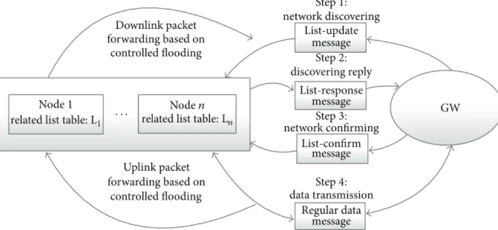
So far the details of our proposed routing protocol REALFLOW have been presented. In summary, four pro-ceeding steps and four message types are involved in REALFLOW. First, the gateway broadcasts list-update mes-sages to discover the latest network topology. Then each node replies with a list-response message to report their parent nodes and add itself into the related node lists in all intermediate nodes. After receiving all responses from all nodes, the gateway is able to obtain the latest network topology and calculate the latest TDMA scheduling decisions and send them back to all nodes by list-confirm messages. Finally, all nodes are able to communicate with the gateway based on controlled flooding according to our forwarding rules for both uplink and downlink. A summary of all steps and corresponding messages is shown inFigure 2.
Downlink packet forwarding based on
controlled flooding
Node1 related list table: L1
Noden related list table: Ln · · · Uplink packet forwarding based on controlled flooding Step1: network discovering Step2: discovering reply Step3: network confirming Step4: data transmission List-update message message message message List-response List-confirm Regular data GW
Figure 2: REALFLOW proceeding summary.
(1) Extract𝐴src,𝐴dstand𝑠pktfrom the received packet (2) if 𝐴src= 𝐴gw then
(3) if 𝐴dst∈ L then
(4) Construct the unique pair𝑃 = (𝑠pkt, 𝐴dst)
(5) if 𝑃 ∉ H then
(6) Update𝑇age
(7) if 𝑇age< 𝑇refresh then
(8) H = H ∪ {𝑃} (9) Forward (10) end if (11) end if (12) end if (13) else if 𝐴dst= 𝐴gw then (14) if 𝐴src∈ L then
(15) Construct the unique pair𝑃 = (𝑠pkt, 𝐴src)
(16) if 𝑃 ∉ H then
(17) Update𝑇age
(18) if 𝑇age< 𝑇refreshthen
(19) H = H ∪ {𝑃} (20) Forward (21) end if (22) end if (23) end if (24) end if (25) Drop
Algorithm 4: Packet forwarding procedure.
4.4. Example: Reliable Real-Time Flooding-Based Routing Protocol. Figure 3 illustrates an example of REALFLOW. Transmissions between Node 7 and the gateway are described in detail. In the beginning, the gateway broadcasts a list-updated message. Propagation routes of the list-list-updated message to Node 7 are shown as solid arrows in the figure. Numbers on the arrows are the absolute values of RSSI from one node to another. We define𝐾max as 2, since multipath diversity is achieved and not too much network resource is required. Node 7 gets five copies of list-updated messages from Nodes 1, 2, 3, 6, and 8. Compared with other nodes, 𝑟pktfrom Nodes 1 and 2 are minimum. Thus, Node 7 chooses
6 7 8 9 3 4 2 1 5 GW 76 83 77 75 85 78 72 69 73 72 76 71 74 71
Figure 3: An example of REALFLOW: route establishment and packet forwarding between the gateway and Node 7.
Nodes 1 and 2 to be its parent nodes. From the figure, Node 1 considers the gateway and Node 2 as its parent nodes, and Node 2 selects the gateway and Node 3 to be its parent nodes. After receiving the list-updated message, Node 7 shall reply a list-response message to the gateway. When Nodes 1 and 2 receive the list-response message, since its address is included inNfwd, so they add the address of Node 7 to their related
node lists and forward it to their parent nodes. After all list-response messages are sent to the gateway, related node lists are generated in all nodes, and the gateway is able to calculate the latest network topology. Then the gateway needs to send list-confirmed messages to all nodes with the confirmation of related node lists and scheduling decisions.
After the related node lists are confirmed by the gateway, when Node 7 sends a packet to the gateway by flooding, only Nodes 1 and 2 are able to forward the packet, and other nodes will drop the packet automatically. By this means, packets are transmitted from Node 7 to the gateway via two paths,
so the multipath diversity is achieved. Moreover, flooding transmission is severely controlled and restricted within a small range to avoid excessive packet forwarding.
Usually, many research works reach a consensus that flooding method is much less efficient at packet transmission than unicasting, since much more network resources may be required for flooding. However, it is not always the truth. In this example, as TDMA is used on the MAC layer, for uplink, only 3 timeslots are required to achieve two-path diversity. For traditional unicast routing protocol, four timeslots are needed to achieve the same diversity. A similar situation happens in the reversed direction for the downlink. More analyses of required timeslots, as well as complexity and reliability, are discussed in the following subsection.
4.5. Theoretical Analysis of REALFLOW. In this subsection,
the complexity of the algorithm, the network resource effi-ciency, and reliability performance are analyzed by theory.
4.5.1. Algorithm Complexity. REALFLOW consists of four
algorithms as shown above. Algorithms 1, 2, and 4 run distributively in each node in the network without requiring the gateway to participate, including related node list gen-eration. The complexity of these three algorithms is𝑇(𝑛) = 𝑂(1), where 𝑛 is the number of nodes in the network excluding the gateway. In a centralized IWSN, the gateway is a bottleneck for the whole network. Thus, these algorithms release the gateway from high workload. Even if the network size increases significantly, the workload from these three algorithms for each node including the gateway remains the same.
OnlyAlgorithm 3should run at the gateway to generate the network topology. The parameter𝐾max, which is the max-imum allowed parent node number, can affect the complexity of the algorithm from Lines 4 and 5. It is a predefined value and can be considered as a constant. In the worst case, there is only one node directly connected to the gateway, and all other nodes are able to find𝐾maxparent nodes. Therefore, the
worst-case complexity ofAlgorithm 3is:
𝑇 (𝑛) = 5𝐾max𝑛2+ 16𝐾max𝑛 + 2𝑛 + 8 − 𝐾max= 𝑂 (𝑛2) .
(4) Compared with other routing protocols for IWSNs, such as [34], where the complexity is𝑂(𝑛3), REALFLOW hugely decreases the time complexity. In centralized IWSNs, the latest routing and scheduling decisions are all made by the gateway or network manager. Thus, low complexity is severely important for centralized IWSNs, since it may take the gateway or network manager excessively long time for the calculations if the routing algorithm is overcomplicated. During the processing period, the whole network may behave abnormally, since all nodes in the network do not have the latest routing information. Although the optimal scheduling algorithm is not specified in this paper, the complexity of the simplified scheduling scheme is still no more than that of the topology generation algorithm. Therefore, the overall complexity remains at the same level.
GW 1 1 2 2 Y − 1 Y · · · · · · · · · · · · · · · . . . X − 1 X
Figure 4: An example of a multihop IWSN for analysis.
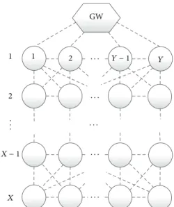
4.5.2. Network Resource Efficiency. Regarding a general case,
a TDMA IWSN consisting of𝑋 ⋅ 𝑌 nodes is constructed, as shown inFigure 4. On each hop, there exist 𝑌 nodes, and the furthest nodes are𝑋 hops away from the gateway. For simplicity, we assume that a node is able to communicate with any parent node, child node, or sibling node, and each node periodically communicates with the gateway with the same refresh interval. Here, network resource efficiency refers to the usage of time slots. Flooding-based transmission is deemed to be inefficient due to excessive transmissions. In order to explore the network resource efficiency of REALFLOW, we intend to calculate the upper and lower bound of the total required timeslots of the entire network. To obtain the upper bound, we assume that any node is able to find𝐾maxparent nodes or sibling nodes, and we also assume that all nodes directly connected to the gateway are always involved in forwarding packets from nodes more than one hop away. Then the maximum required timeslots𝑅upfor the
whole network is calculated as 𝑅up = { { { { { { { { { { { { { { { { { { { { { { { { { { { { { { { { { { { { { { { { { { { { { { { { { 𝑌 (𝐾max+ (1 + 𝑌) + (1 + 𝑌 + 𝐾max) + ⋅ ⋅ ⋅ + (1 + 𝑌 + 𝐾max+ 𝐾2 max+ ⋅ ⋅ ⋅ + 𝐾𝑋−2max)) , 𝑌 ≥ 𝐾𝑋−2 max, 𝑋 > 2 𝑌 (𝐾max+ (1 + 𝑌) + (1 + 𝑌 + 𝐾max) + ⋅ ⋅ ⋅
+ (1 + 2𝑌 + 𝐾max+ 𝐾max2 + ⋅ ⋅ ⋅ + 𝐾max𝑋−3)) ,
𝐾max𝑋−3≤ 𝑌 < 𝐾max𝑋−2, 𝑋 > 3 𝑌 (𝐾max+ (1 + 𝑌) + (1 + 𝑌 + 𝐾max) + ⋅ ⋅ ⋅ + (1 + 3𝑌 + 𝐾max+ 𝐾2 max+ ⋅ ⋅ ⋅ + 𝐾max𝑋−4)) , 𝐾𝑋−4 max ≤ 𝑌 < 𝐾max𝑋−3, 𝑋 > 4 .. . 𝑌 (𝐾max+ (1 + 𝑌) + ⋅ ⋅ ⋅ + (1 + (𝑋 − 1) 𝑌)) , 1 ≤ 𝑌 < 𝐾max, (5)
and (5) can be further simplified as 𝑅up = { { { { { { { { { { { { { { { { { { { { { { { { { { { { { { { { { { { { { { { { { { { { { { { { { { { { { { { { { 𝑌 [𝐾max+ 𝑌 (𝑋 − 1) +𝐾max(𝐾 𝑋−1 max − 1) (𝐾max− 1)2 + 1 − 𝑋 𝐾max− 1] , 𝑌 ≥ 𝐾𝑋−2max, 𝑋 > 2 𝑌 [𝐾max+ 𝑌 (𝑋 − 1) + (𝑖 − 1) 𝑖𝑌 2 +𝐾max(𝐾 𝑋−𝑖 max− 1) (𝐾max− 1)2 +(𝑖 − 1) 𝐾𝐾max𝑋−𝑖+1− 𝑋 + 1 max− 1 ] , 𝐾 𝑋−𝑖 max≤ 𝑌 < 𝐾max𝑋−𝑖+1, 𝑋 > 𝑖, 𝑖 = 3, . . . , 𝑋. (6) Different from upper bound calculation, there are two theoretical lower bounds for REALFLOW. To calculate the first lower bound, we still assume that all nodes can find 𝐾maxparent nodes or sibling nodes, but we also assume that redundant paths overlap with each other at maximum extent, which means that nodes with the same hops away from the gateway share the same parent nodes. Thus, the first lower bound of required timeslots𝑅low1is calculated as
𝑅low1 = { { { { { { { { { 𝑌 (1 + (1 + 𝐾max) + (1 + 2𝐾max) + ⋅ ⋅ ⋅ + (1 + (𝑋 − 1) 𝐾max)) 𝑌 ≥ 𝐾max 𝑌 (1 + (1 + 𝑌) + (1 + 2𝑌) + ⋅ ⋅ ⋅ + (1 + (𝑋 − 1) 𝑌)) , 𝑌 < 𝐾max, (7) and (7) can be further simplified as
𝑅low1= { { { { { 𝑋𝑌 + (𝑋 − 1) 𝑋𝑌𝐾max 2 , 𝑌 ≥ 𝐾max 𝑋𝑌 + (𝑋 − 1) 𝑋𝑌2 2 , 𝑌 < 𝐾max. (8)
In reality, a node cannot always find𝐾maxparent or sibling node due to interferences or network topology. The second theoretical lower bound can be obtained if each node can only find one available path. Thus, we assume that each node is only able to find one parent or sibling node. The required time slots for the whole network𝑅low2is
𝑅low2= 𝑌 + 2𝑌 + ⋅ ⋅ ⋅ + 𝑋 ⋅ 𝑌 = (1 + 𝑋) 𝑋𝑌
2 . (9)
From (6), since𝐾𝑋−1max,𝐾max𝑋−𝑖, and𝐾max𝑋−𝑖+1determine the increment of 𝑅up, when the hop number of the node 𝑋
increases, the maximum required timeslots also grow rapidly. It indicates that REALFLOW may not be very resource efficient in an extremely large size of a network, where nodes
are many hops away from the gateway. However, REALFLOW can be applied in IWSNs for two reasons. The first reason is that in a great number of industrial applications the refresh rate is extremely fast, at the order of seconds, or even millisec-onds [2]. Thus, the network size is seriously constrained and cannot be too large. Secondly, since the gateway is allowed to send commands to shrink the related node list in each node. The flooding range can be further restricted. Even if the network size is large with hundreds of nodes, for industrial applications with the slow refresh rate, REALFLOW can still be resource efficient. Moreover, (6) is calculated based on the worst case in which every node has different parent nodes. However, in reality, many nodes may share the same parent nodes, so the worst case happens very rarely.
When nodes with the same hops away from the gateway share the same parent nodes, (8) is obtained. According to (8), even if the hop number𝑋 increases, the total required time slots will not grow extraordinarily. Equation (9) is an extreme case in which all nodes can only find one path to the gateway. The required timeslot number is the same as unicast transmission. Thus, it is unnecessary to discuss.
In reality, the required timeslot number of the whole network is most probably between (6) and (8). Therefore, the network resource consumption when applying REALFLOW is definitely not overwhelming to the network, although the control-flooding mechanism is applied.
4.5.3. Reliability Performance. As we emphasized previously,
high reliability is one of the most important requirements of IWSNs. REALFLOW is initially designed to achieve high reliability by high multipath diversity.
We use the same network topology (Figure 4) for the reliability analysis. The packet delivery ratio (PDR) of a node 𝑋 hops away from the gateway is calculated as follows. We assume that there are𝑍𝑖nodes, which are𝑖 hops away from the gateway and are intermediate nodes to the destination node. Also for simplicity, we assume that any node out of these 𝑍𝑖 nodes is able to directly find 𝐾max parent nodes, if this node is more than one hop away from the gateway. Furthermore, we assume that all channels are symmetric. This assumption is valid if the bandwidth, transmission power, and hardware for both uplink and downlink are the same. 𝑃𝑑(𝑘)(𝑗) is the PDR of the 𝑗th node to its 𝑘th parent node if this node is more than one hop away from the gateway; otherwise, 𝑃𝑑𝑠(𝑘)(𝑗) is the PDR of the 𝑘th redundant path from the 𝑗th node to the gateway.𝑃𝑑prt(𝑖, 𝑗) is the overall PDR of the 𝑗th node from𝑖th hop to all its parent nodes at (𝑖 − 1)th hop. 𝑃hop
𝑑 (𝑖) is the overall PDR of nodes from 𝑖th hop to (𝑖 − 1)th
hop. Then we have
𝑃prt 𝑑 (𝑖, 𝑗) = { { { { { { { { { { { { { { { { { { { { { { { 𝑃(1) 𝑑 (𝑗) + (1 − 𝑃𝑑(1)(𝑗)) 𝑃𝑑(2)(𝑗) + ⋅⋅⋅ + (𝐾max∏−1 𝑚=1 (1 − 𝑃 (𝑚) 𝑑 (𝑗))) 𝑃𝑑(𝐾max)(𝑗) , 𝑖 ̸= 1 𝑃(1) 𝑑𝑠 (𝑗) + (1 − 𝑃𝑑𝑠(1)(𝑗)) 𝑃𝑑𝑠(2)(𝑗) + ⋅⋅⋅ + (𝐾max∏−1 𝑚=1 (1 − 𝑃 (𝑚) 𝑑𝑠 (𝑗))) 𝑃𝑑𝑠(𝐾max)(𝑗) , 𝑖 = 1, (10)
𝑃hop 𝑑 (𝑖) = 𝑃 prt 𝑑 (𝑖, 1) + (1 − 𝑃 prt 𝑑 (𝑖, 1)) 𝑃 prt 𝑑 (𝑖, 2) + ⋅ ⋅ ⋅ + (𝑍∏𝑖−1 𝑚=1 (1 − 𝑃prt 𝑑 (𝑖, 𝑚))) 𝑃 prt 𝑑 (𝑖, 𝑍𝑖) . (11)
Finally the overall PDR between the gateway and the𝑗th node with𝑙 hops away from the gateway 𝑃𝑑overall(𝑙), 𝑙 > 1, can be calculated as 𝑃overall 𝑑 (𝑙) = 𝑃𝑑prt(𝑙, 𝑗) 𝑙−1 ∏ 𝑚=1 𝑃hop 𝑑 (𝑚) . (12)
It is apparent that from (10)𝑃𝑑prt(𝑖, 𝑗) will increase if 𝐾max increases. In order to investigate if 𝑃𝑑hop(𝑖) monotonically increases with𝑃𝑑prt(𝑖, 𝑗), the partial derivative can be calcu-lated as 𝜕𝑃hop 𝑑 (𝑖) 𝜕𝑃prt 𝑑 (𝑖, 𝑗) = 𝐾∏max 𝑚=1,𝑚 ̸= 𝑗 (1 − 𝑃prt 𝑑 (𝑖, 𝑚)) , ∀𝑗 ∈ [1, 𝐾max] . (13) Since 0 ≤ 𝑃𝑑prt(𝑖, 𝑚) < 1, it follows that 𝜕𝑃𝑑hop(𝑖)/ 𝜕𝑃prt
𝑑 (𝑖, 𝑗) > 0. From (12), it is also apparent that𝑃𝑑overall(𝑙)
will increase if𝑃𝑑hop(𝑚) increases. Thus, we can conclude that
𝑃overall
𝑑 (𝑙) will definitely increase if 𝐾max increases. Finally,
we prove that, by increasing𝐾max, we can definitely improve the overall reliability performance of REALFLOW, given that there are more available paths to use.
However, according to (6) and (8), the required number of time slots will also increase at the same time if we increase 𝐾max. Therefore, there is a trade-off between the reliability performance and the network resource efficiency.
5. Experimental Setup
The reliability and real-time performance of REALFLOW are evaluated and compared with those of three traditional routing protocols via simulations in the discrete event simu-lator QualNet. In this section, the experimental settings and simulation scenarios are described as follows.
5.1. Simulation Settings. We construct a centralized mesh
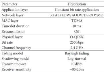
IWSN placed within a 100× 100 m area. Two types of devices are involved in our simulations, namely, a gateway and a number of nodes, with the complete communication protocol stack. On the network layer, we implemented REALFLOW in QualNet and utilize three other existing transitional routing protocols from QualNet. Besides the network layer, the configurations from other layers are summarized inTable 1.
The configuration of the physical layer is defined accord-ing to the standard IEEE 802.15.4 [35], where the com-munication operates at 2.4 GHz with the bit rate 250 kbps. In order to provide deterministic communication, TDMA mechanism is applied rather than traditional CSMA/CA mechanism. The timeslot duration is determined according to the standard WirelessHART. The reasons for turning off
Table 1: The protocol parameters.
Parameter Description
Application layer Constant bit rate application
Network layer REALFLOW/AODV/DSR/DYMO
MAC layer TDMA
Timeslot duration 10 ms
Retransmission Off
Physical layer O-QPSK
Bit rate 250 kbps
Channel frequency 2.4 GHz
Fading model Rayleigh fading
Shadowing model Log-normal
Transmit power 10 dBm
Receiver sensitivity −85 dBm
retransmissions are due to the stringent real-time perfor-mance requirement and fast refresh rates. Retransmissions bring significantly higher delivery latency, so packets may be already outdated when arriving at their destinations if the deadlines are very short. For many industrial applications, outdated packets are of limited use for destinations. In the standard WirelessHART and ISA 100a, channel hopping is used on the MAC layer as well. For simplicity, we also disable channel hopping in our simulation. On the network layer, besides REALFLOW, we choose three traditional routing protocols, AODV, DSR, and DYMO provided by Qual-Net. These traditional routing protocols have been already applied in traditional WSNs. Constant bit rate application is selected on the application layer to provide continuous data transmissions.
Besides the protocol stack, the channel parameters and node settings are also included in Table 1. As mentioned before, due to a great number of obstacles, NLOS com-munication dominates in many industrial environments [8, 9]. Therefore, we choose the Rayleigh fading model. We assume that industrial environments are relatively static, so log-normal model is chosen as the shadowing model. According to the standard WirelessHART, the maximum allowed radio output power is 10 dBm. To achieve the longest communication distance, we set the transmission power as 10 dBm. This radio output power has been already supported by existing devices, such as CC2591 [36]. We choose the receiver sensitivity as−85 dBm to filter out too weak signals. A great number of existing devices are able to support this sensitivity such as CC2591 and CC2531 [37]. In order to prove our simulation setting suitable, we place two nodes in QualNet with around 40 meters away and measure RSSI value at the receiver side. According to the measurement result, although the measured RSSI values from our simulation are around 10 dB less than those from the real environment, the variance of the signal strength follows the same trend. RSSI values may differ from different platforms, so we can consider the channel status to be relatively similar to that in a real industrial environment.
50 m (a) Scenario 1 50 m (b) Scenario 2 50 m (c) Scenario 3
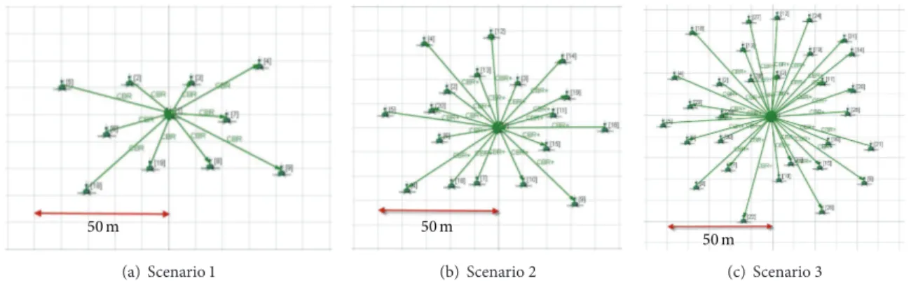
Figure 5: Three simulation scenarios. A mesh network is created in each scenario. The arrows between nodes and the gateway do not mean the direct links but are the QualNet configurations on the application layer for periodic data transmissions.
5.2. Simulation Scenarios. We set up three different scenarios
to show the results with respect to reliability and real-time performance from REALFLOW. In each scenario, we consider both uplink and downlink transmissions. Thus, each node periodically sends packets to the gateway, and the gateway also periodically sends packets to all nodes. The refresh intervals from three scenarios are 250 ms, 500 ms, and 1 s, respectively. These refresh rates are commonly seen in existing industrial applications [2].
Due to the fast refresh rate, the size of the network is strictly constrained. The faster the refresh rate is, the fewer the timing slots and bandwidth resources are available for each node. If too many nodes exist in the network, the network resources may become unschedulable. It is also important that due to the fast application refresh rate and stringent reliability and timing requirements, the hop number of each node in the network cannot be too large. Not only does larger hop number require more network resources and timing for packet forwarding, but also the end-to-end transmissions are at the risk of higher failure rate. This is one of the major differences between time-critical IWSNs and traditional WSNs. Usually the date refresh rate of traditional WSNs is much lower. Moreover, traditional WSNs have a much higher tolerance to transmission failures. Therefore, the sizes of the network from three scenarios are randomly selected as 10, 18, and 30, respectively, excluding the network manager.
In each scenario, 50% are sensors and 50% actuators. Three scenarios are shown inFigure 5. It is very important to know that arrows inFigure 5do not mean that all nodes are able to communicate with the gateway directly. These arrows are the configurations from QualNet to show that all nodes are configured to communicate with the gateway periodically. If nodes are farther away than one hop distance to the gateway, intermediate nodes will be involved automatically.
After mesh networks are established, all nodes peri-odically send packet to the gateway at a certain refresh rate, and the gateway also periodically sends packet to all nodes. Then we measure packet delivery ratio (PDR), end-to-end transmission latency, and network recovery time. PDR measurements indicate the reliability of different routing protocols. End-to-end latency is calculated from the time
when a packet is generated to the time when it arrives at the final destination, which reveals the real-time performance. The network recovery time means the time period spent by a routing protocol on recalculating a new path. It shows the robustness of routing protocols to be tolerant of network topology changes. These are the most important criteria to validate a well-qualified routing protocol for IWSNs.
6. Evaluation Results and Analysis
This section describes the simulation results from all three scenarios, covering the comparison between REALFLOW and three traditional routing protocols. Results of reliability, real-time performance, and network recovery time are ana-lyzed separately in three subsections.
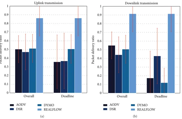
6.1. Packet Delivery Ratio. All PDRs from three scenarios are
measured in two ways, namely, overall PDR and deadline PDR. Overall PDRs are measured based on all received packets at the destinations without considering application deadlines, whereas outdated packets are discarded when measuring deadline PDRs. Both PDRs from uplink and downlink are measured separately. Simulation results from three scenarios are shown in Figures6,7, and8, respectively. From the results, we observe that PDRs measured from all scenarios for both uplink and downlink are much higher than the other three traditional routing protocols. Even in Scenario 3 where nodes are placed further away from each other, REALFLOW is still able to achieve more than 70% average PDRs for both uplink and downlink. This observation is mainly because packets are always sending via several paths from the sources to the destinations by our routing protocol, so the probability of packets arriving at the destinations is much higher. Therefore, even if the channel is in a bad status where broken links occur frequently, packets may be still able to find one path to the destination. It is also notable that overall PDRs and deadline PDRs from REALFLOW are the same, since all outdated packets have been discarded at every intermediate node at their respective deadlines.
Compared with REALFLOW, traditional routing proto-cols perform much worse in the Scenario 3. Not only are all deadline PDRs of traditional routing protocols for both
Overall Deadline 0 0.1 0.2 0.3 0.4 0.5 0.6 0.7 0.8 0.9 1 P ac k et deli ve ry ra tio Uplink transmission AODV DSR DYMO REALFLOW (a) Overall Deadline 0 0.1 0.2 0.3 0.4 0.5 0.6 0.7 0.8 0.9 1 P ac k et deli ve ry ra tio Downlink transmission AODV DSR DYMO REALFLOW (b)
Figure 6: PDRs of different routing protocols in Scenario 1.
Overall Deadline 0 0.1 0.2 0.3 0.4 0.5 0.6 0.7 0.8 0.9 1 P ac k et deli ve ry ra tio Uplink transmission AODV DSR DYMO REALFLOW (a) Overall Deadline 0 0.1 0.2 0.3 0.4 0.5 0.6 0.7 0.8 0.9 1 P ac k et deli ve ry ra tio Downlink transmission AODV DSR DYMO REALFLOW (b)
Figure 7: PDRs of different routing protocols in Scenario 2.
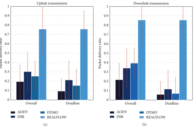
uplink and downlink much lower than those of REALFLOW, but also the overall PDRs of those routing protocols are also quite low. For instance, in Scenario 3, deadline PDRs from all three traditional routing protocols are around 10%, much lower than the PDRs from REALFLOW, 75%. The standard
deviations from all routing protocols are similar, which indicates the dynamic changes of the channel status. There are several reasons for the unsatisfying reliability performance of these three traditional routing protocols. The first reason is lack of redundant paths. These traditional routing protocols
Overall Deadline 0 0.1 0.2 0.3 0.4 0.5 0.6 0.7 0.8 0.9 1 AODV DSR DYMO REALFLOW P ac k et deli ve ry ra tio Uplink transmission (a) Overall Deadline 0 0.1 0.2 0.3 0.4 0.5 0.6 0.7 0.8 0.9 1 P ac k et deli ve ry ra tio Downlink transmission AODV DSR DYMO REALFLOW (b)
Figure 8: PDRs of different routing protocols in Scenario 3.
utilize only one route to forward all packets. Once any broken link occurs in this path, packets fail to be delivered to the destination. Secondly, traditional routing protocols are often used along with ARQ mechanism. Once transmission failure happens, the sender will retransmit the failed packets until they are successfully received or up to maximum retried times. As we described above, since retransmissions may introduce much longer delay, outdated packets are of limited use for destinations. Thus, ARQ is not used in our simulation. Without retransmissions, the traditional routing protocols can hardly achieve high reliability. The last reason is that these traditional routing protocols are initially designed for traditional ad hoc networks instead of industrial centralized networks. Therefore, under these IWSN settings, REALFLOW significantly outperforms traditional routing protocols in the reliability performance.
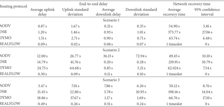
6.2. End-to-End Latency. Average uplink and downlink
transmission latency from three scenarios for both uplink and downlink as well as their standard deviations are shown inTable 2. According to the simulation results, the average uplink and downlink delays of REALFLOW are much lower than the other three routing protocols. It is also notable that even if considering the standard deviations, the transmission latencies are still below the application deadlines. The decent real-time performance of REALFLOW can be explained as follows. Firstly, for REALFLOW, packets are only buffered at intermediate nodes until next available timeslot to transmit. Even if partial links of the network are broken, intermediate nodes will not spend any time on searching for the next hop, which greatly accelerates the packet forwarding procedures.
However, for traditional routing protocols, if the links are broken, it will take them extremely long time to find the next available hop. Finally, the packet age is calculated through the time when the packet is generated and checked by all intermediate nodes. Outdated packets will be discarded automatically. Therefore, more network resources can be used to forward valid packets, which also shorten the end-to-end transmission delay. Therefore, REALFLOW can achieve extremely low end-to-end transmission delay. However, these advantages are not held by three traditional routing protocols. Packet ages calculated by traditional routing protocols are based on the packet hop number instead of existing time. Moreover, according to traditional routing protocols, nodes frequently exchange information to update the latest route status. Thus, packets may be buffered at intermediate nodes for long time until the next hop is found. According to the comparison, REALFLOW is proven to be a well-qualified routing protocol for real-time transmissions in IWSNs.
6.3. Network Recovery Time. As we mentioned previously, a
routing protocol should be tolerant of topology changes, such as intermediate nodes halting. Thus, in this experiment, we halt an intermediate node at a certain time during simulation. Then, the network recovery time is measured by observing the time when a new route is established. During the network recovery period, transmissions from certain nodes may be temporarily terminated, so a new path should be established as soon as possible. The network recovery time of different routing protocols from three scenarios is also shown in Table 2. Because REALFLOW always utilizes more than one path to forward packets, even if one intermediate node
Table 2: Simulation results of average latency and network recovery time for three scenarios.
Routing protocol End-to-end delay Network recovery time
Average uplink delay Uplink standard deviation Average downlink delay Downlink standard deviation Average recovery time 95% confidence interval Scenario 1 AODV 0.87 s 1.67 s 0.21 s 0.35 s 54.90 s 5.81 s DSR 1.20 s 1.46 s 0.93 s 1.01 s 373.77 s 27.06 s DYMO 1.51 s 2.71 s 0.90 s 0.71 s 63.74 s 4.48 s REALFLOW 0.09 s 0.02 s 0.08 s 0.07 s 1 timeslot 0 s Scenario 2 AODV 12.00 s 26.77 s 36.15 s 72.94 s 49.45 s 10.10 s DSR 14.79 s 41.76 s 0.20 s 0.28 s 219.91 s 10.79 s DYMO 24.75 s 64.68 s 0.85 s 3.21 s 62.024 s 7.54 s REALFLOW 0.30 s 0.09 s 0.11 s 0.10 s 1 timeslot 0 s Scenario 3 AODV 3.47 s 7.01 s 7.86 s 6.26 s 50.12 s 8.76 s DSR 21.45 s 22.80 s 3.78 s 10.95 s 198.16 s 14.04 s DYMO 18.86 s 37.67 s 1.17 s 1.69 s 66.76 s 17.10 s REALFLOW 0.49 s 0.26 s 0.51 s 0.24 s 1 timeslot 0 s
halts or one path is blocked, the packets are still able to arrive at the destination via other paths without requiring to establish new paths. Therefore, a seamless transition of the topology change can be achieved by REALFLOW, shown in the results. However, for traditional routing protocols, routing information needs to be updated timely by all nodes. Once a previous path is blocked, traditional routing protocols need to recalculate the latest routing information and try to find a new route. Depending on the channel condition, the time consumption of finding a new path is unpredictable and not deterministic. According to the simulation results, we observe that it took extremely long time for traditional routing protocols to establish a new path. Since packet delivery is blocked, unexpected operations may be taken at the receiver side, which is unacceptable to a great number of industrial applications. Therefore, the result reveals that REALFLOW is more robust for industrial automation.
7. Conclusions and Future Work
In this paper, we abstract the challenges on how to design a usable and robust routing protocol in IWSNs for industrial automation. Then REALFLOW is proposed to address all these challenges of deploying IWSNs for industrial pur-pose. Reliability, real-time performance, robustness, and node workload are thoroughly considered as REALFLOW designed. Instead of traditional routing tables, a related node list is distributively generated in each node and utilized to assist with packet forwarding. Packet transmissions for uplink and downlink are based on the controlled flooding mechanism and several other forwarding criteria. The simu-lation shows the outstanding improvement in both reliability and real-time performance, compared with traditional rout-ing protocols. Moreover, a seamless transition in the event
of topology change can be achieved by our routing protocol. Since our goal is to deploy IWSNs for industrial control systems, supporting hundreds of nodes in a large scale of networks is out of the scope of this paper.
In future work, REALFLOW can be further improved to support mobility of nodes, if industrial applications require. We shall also continue to look for an optimal schedul-ing scheme to enhance REALFLOW. Implementation of REALFLOW in real devices and conducting experiments in practical industrial environments is also of the most importance. Although low energy consumption is not the main issue of REALFLOW, to evaluate and analyze the overall energy consumption, compared to other routing protocols, are also parts of our future work.
Conflict of Interests
The authors declare that there is no conflict of interests regarding the publication of this paper.
References
[1] A. Willig, “Recent and emerging topics in wireless industrial communications: a selection,” IEEE Transactions on Industrial Informatics, vol. 4, no. 2, pp. 102–122, 2008.
[2] J. Akerberg, M. Gidlund, and M. Bjorkman, “Future research challenges in wireless sensor and actuator networks targeting industrial automation,” in Proceedings of the 9th IEEE Interna-tional Conference on Industrial Informatics (INDIN '11), pp. 410– 415, Caparica, Portugal, July 2011.
[3] V. C. Gungor and G. P. Hancke, “Industrial wireless sensor net-works: challenges, design principles, and technical approaches,” IEEE Transactions on Industrial Electronics, vol. 56, no. 10, pp. 4258–4265, 2009.